US492910A - Machine for edging razors - Google Patents
Machine for edging razors Download PDFInfo
- Publication number
- US492910A US492910A US492910DA US492910A US 492910 A US492910 A US 492910A US 492910D A US492910D A US 492910DA US 492910 A US492910 A US 492910A
- Authority
- US
- United States
- Prior art keywords
- carriage
- grinding wheel
- razors
- razor
- movable
- Prior art date
- Legal status (The legal status is an assumption and is not a legal conclusion. Google has not performed a legal analysis and makes no representation as to the accuracy of the status listed.)
- Expired - Lifetime
Links
Images
Classifications
-
- B—PERFORMING OPERATIONS; TRANSPORTING
- B24—GRINDING; POLISHING
- B24B—MACHINES, DEVICES, OR PROCESSES FOR GRINDING OR POLISHING; DRESSING OR CONDITIONING OF ABRADING SURFACES; FEEDING OF GRINDING, POLISHING, OR LAPPING AGENTS
- B24B3/00—Sharpening cutting edges, e.g. of tools; Accessories therefor, e.g. for holding the tools
- B24B3/36—Sharpening cutting edges, e.g. of tools; Accessories therefor, e.g. for holding the tools of cutting blades
- B24B3/52—Sharpening cutting edges, e.g. of tools; Accessories therefor, e.g. for holding the tools of cutting blades of shear blades or scissors
Definitions
- My invention relates to improvements in edging machines particularly applicable for razors and similar articles, and has for its object the production of a simple, effective, and practical construction, which is easily operated and is durable and efficient in use: to this end the invention consists, essentially, in a grinding wheel, a carriage movable rectilinearly across the face of the grinding wheel, a hinged carriage section movable toward and away from the grinding Wheel, astop for limiting the movement of the carriage, Va clamp for securing the razor to the carriage, a heart shaped cam for moving the carriage, and in the detail construction and arrangement of the parts, all as hereinafter more particularly described and pointed out in the claims.
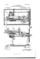
- Figures 1 and 2 are respectively top plan and front elevation of my improved invention, the razor carriage being shown in its extreme inward position in both views.
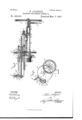
- Fig. 4. is a transverse sectional View, taken on line 4r-4*
- Fig. 5 is a sectional view similar to Fig. 4 representing the hinged section of theA razor carriage as swung backwardly from the grinding wheel.
- Fig. 6 is a detached view of the razor carriage and its hinged section
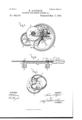
- Fig. 7 is an isometric perspective of the revoluble carriage actuating cam and the gear for operating the same.
- -A- represents the frame of my machine, which consists preferably of a pair of upright standards ,-a-amounted on any suitable construction of table --tt2 and formed with journal bearings andsupports for the various parts of my invention.
- the grinding wheel -B- is journaled on a Shaft -bsupported in the bearing-tof the upright -aand provided with a gear -B.
- a series of Wheels ⁇ ,-B- only one of which is illustrated having their surfaces of varying density or roughness so that the razor edge may be brought to thek required keenness in the usual manner; first by a rough surface, then by one somewhat ner, and lastly by a leather face.
- These wheels are formed with journal openings b, which loosely encircle the outwardly projecting end of the spindle -b-, and are firmly secured thereto by set screws or other suitable clamps --b2.
- --C- represents the main driving gear journaled on a shaft -cmounted in the bearing -ct4 of the upright -a-, a suitable crank -C- is secured .to this gear, and a small pinion -D- mounted on one end ot' a shaft -dmeshes with the gear O
- the shaft d is journaled in the bearings -dand --d2- mounted respectively upon the uprights -aand -ot-, and at its other end is a gear -D- which meshes with the gear -B-, whereby, when the crank -C is revolved, the grinding wheel -B- is also revolved.
- gears -C-D-D- and '-B- are so relatively proportioned and arranged that the operator may, with comparative ease, revolve the grinding wheel -B- from fifteen hundred to tfwo thousand revolutions per minute, thus enabling the wheel to act practically and effectively upon the razor.
- the carriage -E- consists of the main section -E- and the hinged section -E2-, both of which are movable rectilinearly along a guide e Xed in a bearing -eof the upright -ctand having its opposite eX- tremities passed through eyes -e2-e3- and -etupon the movable and main carriage sections.
- the main'carriage section is formed with the arm e5-provided with a slot -e6-, which registers with a pin e7 directly above the axis of a heart shaped cam -F- for reciprocating said carriage and serves an additional guide for the carriage.
- the hinged carriage section is formed at its opposite extremities with the heads -eS-esprovided with the open slots -egforpreceiving the razor blade -gand with set screws or clamps -g-- for lirmly securing the razor blade in position as shown at Figs. 1 and 2.
- the eyes IOO --e.2- and -e3 of the hinged carriage section are loosely mounted on the guide -e-, which serves as a pivotal pin therefor in order that the said carriage may be swung toward and away from the face of the grinding wheel, and, when in its backward position, the carriage is stopped from further movement by any suitable stop #-H- upon the upright ct, and, when in its forward position, the blade is sufliciently in advance of the guide -e so that the weight of the blade and the heads wes-egserve to hold the razor blade firmly upon the grinding wheel, although the hinged carriage section may be readily swung backward as previously described.
- the loosely hinged carriage section may be forced backward and forward along the guide its Veye c3- is disposed in the opening -E3 in the eye -94- upon the main carriage section.
- the actuating cam -F- for forcing the carriage backward and forward is, as previously stated, heart shaped as this contour is particularly applicable for transforming a rotary to a reciprocating movement.
- the cam -F- is actuated by an underlying gear -I- to which it is suitably secured as by bolts -f-, the gear -I- being mounted upon a spindle -ljournaled in the bearing -12- upon the laterally extending arm -A- of the upright -c L-.
- the gear -I- is driven by a pinion -zmounted on the shaft -cof the driving wheel -C- in order that when the crank -C- is operated to rotate the grinding wheel -B the cam -F-- may be rotated simultaneously.
- the main section of said carriage is provided with the depend-r ing ⁇ anti' friction rollers -J- and -J2, which bear upon opposite points of said cam and force the carriage backward and forward as the cam is revolved.
- the component parts are simple, effective and durable, the razor is moved across the face of the grinding wheel during the revolution of said wheel, may be readily swung backwardly out of contact with the grinding wheel, may be readily withdrawn when properly finished and replaced by another razor, and, owing to the uniformity of the movement of the rectilinear movement of the razor carriage, the edge of the razor is of uniform thickness. It is evident, however, that the detail construction and arrangement of the parts of my invention may be somewhat varied from that shown or described without departing from the spirit of my invention', hence I do not herein wish to limit myself to such precise detail construction and arrangement.
- a machine for edging razors and similar articles the combination with a frame, a movable grinder ⁇ iournaled onthe frame, a carriage movable across the face of the grinder, a hinged carriage section movable toward and away from the grinder, a stop for .preventing the backward movement of the grinder, a movable clamp for securing the razor to said carriage, a revoluble cam for moving the carriage, and connected gearing between the movable grinder and cam, substantially as and for the purpose set forth.
Landscapes
- Engineering & Computer Science (AREA)
- Mechanical Engineering (AREA)
- Grinding And Polishing Of Tertiary Curved Surfaces And Surfaces With Complex Shapes (AREA)
Description
(No Model.) 3 Sheets-Sheet 2.
N. ALLGIEAR. MACHINE POR EDGING RAZORS, &e. No. 492,910. Patented'Mar. 7, 1893.
nfllTn mmm mii IN A1 THE Nom-ns PETERS co. PHnaLlTuc. vfAsHmt-Tnu. n. c.
www TTORNEYg,
(No Model.) 3 Sheets-Sheet 3.
N. ALLGIEAR. MACHINE POR EDGING RAZORS, dw.
No. 492,910. Patented Mar. 7, 1,893.
ATTONEYS, n
UNITED STATES PATENT OErrcE.
NELSON ALLGIEAR, OF SYRACUSE, NEW YORK.
MACHINE FOR EDGING RAzoRs, am
SPECIFICATION forming part of Letters Patent No. 492,910, dated March '7, 1893.
Application filed January 18, 1892. `Serial No. 418,358. (No model.)
To all whom it may concern:
Be it known that I, NELSON ALLGIEAR, of Syracuse, in the county of Onondaga, in the State of New York, have invented new and useful Improvementsin Machines for Edging Razors and Similar Articles, of which the following, taken in connection with the accompanying drawings, is a full, clear, and exact description.
My invention relates to improvements in edging machines particularly applicable for razors and similar articles, and has for its object the production of a simple, effective, and practical construction, which is easily operated and is durable and efficient in use: to this end the invention consists, essentially, in a grinding wheel, a carriage movable rectilinearly across the face of the grinding wheel, a hinged carriage section movable toward and away from the grinding Wheel, astop for limiting the movement of the carriage, Va clamp for securing the razor to the carriage, a heart shaped cam for moving the carriage, and in the detail construction and arrangement of the parts, all as hereinafter more particularly described and pointed out in the claims.
In describing this invention, reference is had to the accompanying drawings, forming a part of this specification, in which, like letters indicate corresponding parts in all the Views.
Figures 1 and 2 are respectively top plan and front elevation of my improved invention, the razor carriage being shown in its extreme inward position in both views. Fig. Sisalongitudinal sectional View, taken on line -3- 3, Fig. 1. Fig. 4. is a transverse sectional View, taken on line 4r-4*, Fig. 1. Fig. 5 is a sectional view similar to Fig. 4 representing the hinged section of theA razor carriage as swung backwardly from the grinding wheel. Fig. 6 is a detached view of the razor carriage and its hinged section, and Fig. 7 is an isometric perspective of the revoluble carriage actuating cam and the gear for operating the same.
-A- represents the frame of my machine, which consists preferably of a pair of upright standards ,-a-amounted on any suitable construction of table --tt2 and formed with journal bearings andsupports for the various parts of my invention.
The grinding wheel -B- is journaled on a Shaft -bsupported in the bearing-tof the upright -aand provided with a gear -B. I preferably use a series of Wheels `,-B-, only one of which is illustrated having their surfaces of varying density or roughness so that the razor edge may be brought to thek required keenness in the usual manner; first by a rough surface, then by one somewhat ner, and lastly by a leather face. These wheels are formed with journal openings b, which loosely encircle the outwardly projecting end of the spindle -b-, and are firmly secured thereto by set screws or other suitable clamps --b2. a
--C- represents the main driving gear journaled on a shaft -cmounted in the bearing -ct4 of the upright -a-, a suitable crank -C- is secured .to this gear, and a small pinion -D- mounted on one end ot' a shaft -dmeshes with the gear O The shaft d is journaled in the bearings -dand --d2- mounted respectively upon the uprights -aand -ot-, and at its other end is a gear -D- which meshes with the gear -B-, whereby, when the crank -C is revolved, the grinding wheel -B- is also revolved. These gears -C-D-D- and '-B- are so relatively proportioned and arranged that the operator may, with comparative ease, revolve the grinding wheel -B- from fifteen hundred to tfwo thousand revolutions per minute, thus enabling the wheel to act practically and efectively upon the razor.
The carriage -E- consists of the main section -E- and the hinged section -E2-, both of which are movable rectilinearly along a guide e Xed in a bearing -eof the upright -ctand having its opposite eX- tremities passed through eyes -e2-e3- and -etupon the movable and main carriage sections. The main'carriage section is formed with the arm e5-provided with a slot -e6-, which registers with a pin e7 directly above the axis of a heart shaped cam -F- for reciprocating said carriage and serves an additional guide for the carriage. The hinged carriage section is formed at its opposite extremities with the heads -eS-esprovided with the open slots -egforpreceiving the razor blade -gand with set screws or clamps -g-- for lirmly securing the razor blade in position as shown at Figs. 1 and 2.
It will be readily understood that the eyes IOO --e.2- and -e3 of the hinged carriage section are loosely mounted on the guide -e-, which serves as a pivotal pin therefor in order that the said carriage may be swung toward and away from the face of the grinding wheel, and, when in its backward position, the carriage is stopped from further movement by any suitable stop #-H- upon the upright ct, and, when in its forward position, the blade is sufliciently in advance of the guide -e so that the weight of the blade and the heads wes-egserve to hold the razor blade firmly upon the grinding wheel, although the hinged carriage section may be readily swung backward as previously described.
In order that the loosely hinged carriage section may be forced backward and forward along the guide its Veye c3- is disposed in the opening -E3 in the eye -94- upon the main carriage section.
The actuating cam -F- for forcing the carriage backward and forward is, as previously stated, heart shaped as this contour is particularly applicable for transforming a rotary to a reciprocating movement. As preferably constructed, however, the cam -F- is actuated by an underlying gear -I- to which it is suitably secured as by bolts -f-, the gear -I- being mounted upon a spindle -ljournaled in the bearing -12- upon the laterally extending arm -A- of the upright -c L-. The gear -I- is driven by a pinion -zmounted on the shaft -cof the driving wheel -C- in order that when the crank -C- is operated to rotate the grinding wheel -B the cam -F-- may be rotated simultaneously.
In order to transfer motion from the camv -F- to the carriage -E- the main section of said carriage is provided with the depend-r ing` anti' friction rollers -J- and -J2, which bear upon opposite points of said cam and force the carriage backward and forward as the cam is revolved.
As there is more or less liability of that portion of the carriage interposed between thepinV -e7 and the bearing -ebeing sprung by the strain to which the same is subjected in the operation of my machine I provide at said central portion the depending lug or roller K-, which is movable in a gear or guide c formed in a. laterally projecting arm -A2- upon the upright ct- Itis evident that the return movementv of the carriage is readily eected by the engagement of the cam FM with the lrear anti friction roller -J2--, but as a further meansV of affecting the return movement of the carriageV I provide a spring -L- having one Vend secured at L- to the arm -A2- and the other provided with an eye -Z-, which is engaged by the eye --e2- of the hinged carriage section as the same is forced backwardly.
The operation of my invention will be readily perceived from the foregoing description and upon reference to the drawings, and, as
clearly shown and described, the component parts are simple, effective and durable, the razor is moved across the face of the grinding wheel during the revolution of said wheel, may be readily swung backwardly out of contact with the grinding wheel, may be readily withdrawn when properly finished and replaced by another razor, and, owing to the uniformity of the movement of the rectilinear movement of the razor carriage, the edge of the razor is of uniform thickness. It is evident, however, that the detail construction and arrangement of the parts of my invention may be somewhat varied from that shown or described without departing from the spirit of my invention', hence I do not herein wish to limit myself to such precise detail construction and arrangement.
Having thus fully described my invention, what I claim as new, and desire to secure by Letters Patent, is-
l. In an edging machine for razors andsimilar articles, the combination of a revoluble grinding wheel, a carriage movable rectilinearly across the face of the grinding wheel, and provided with a pair of separated heads for alternately supporting the razor and presenting its opposite sides to the grinding wheel, and clamps movable in said heads for securing the razor or similar article to the carriage, substantially as and for the purpose set forth.
2. In an edging machine for razors and similar articles, the combination of a2 revoluble grinding wheel, a carriage movable across the face of the grinding wheel, clamps for securing the razor orsimilar article tothe carriage, and an endless heart shaped cam for moving the carriage transversely across the face of the grinding wheel,.substantially as and for the purpose described.
3. Inlan'edging machine for razors andsimilar articles, the combination of a revol'u'ble grinding wheel, a carriage' movable across the face of the grinding wheel, a hinged carriage section movable toward and away from the grinding wheel, and provided with a pair of separated headsl for alternately supporting the razor andpresenting its oppositesides to the grinding wheel, andl clamps movable in said heads for securing the razor to said hinged carriage section, substantially as and for the purpose specified.
4r. Insanedging machine forrazors and similar articles, the combination of a revoluble rinding wheel andl 'fearing for drivin@r theV g b b b grinding Wheel; of a carriage movable rectilinearly across the face of thegrndingwheel, clamps for securing the razor to the carriage, a heart shaped cam for moving the carriage rectilinearly, and connecting gearing between said cam and grinding wheel, whereby both operate simultaneously, substantially as and for the purpose specified.
5. In an edging machine for razors and similar articles, the combination of a revoluble IOO rob
IIO
grinding Wheel, a carriage movable rectilinearly across the face of the grinding wheel, a hinged carriage section movable toward and away from the grinding Wheel, anti friction rollers upon the carriage, and a revoluble cam for engaging said rollers and operating the carriage, substan tially as and for the purpose described.
6. In an edging machine for razors and similar articles, the combination of a revoluble grinding wheel, a carriage movable rectilinearly across the face of the grinding wheel, an anti friction roller on the carriage connected,substantially as described, to the carriage, a revoluble cam for engaging said roller and operating the carriage, and a spring for retracting the carriage, substantially as and for the purpose specified.
7. In an edging machine for razors and simi-V lar articles, the combination of a revoluble grinding wheel, a carriage movable rectilinearly across the face of the grinding wheel, a guide in proximity to the carriage, a lug connected, substantially as described, to the carriage and a revoluble cam for forcing the carriage backward and forward, substantially as and for the purpose specified.
8. In an edging machine for razors and similar articles, the combination of a revoluble grinding wheel, a carriage movable rectilinearly across the face of the grinding wheel, a guide in proximity to the carriage, a lugconnected, substantially as described, to the carriage, a revoluble cam for forcing the carriage backward and forward, and a spring for retracting said carriage, substantially as described.
9. In an edging machine for razors and similar articles, the combination of a revoluble grinding wheel, a carriage movable rectilinearly across the face ofthe grinding wheel, a guide in proximityk to the carriage, a lug on the carriage movable in said guide, a hinged carriage section movable toward and away from the grinding wheel, a clamp for securing the razor to said carriage, and a revoluble cam for moving the carriage, substantially as and for the purpose set forth.
10. In a machine for edging razors and similar articles, the combination with a frame, a movable grinder `iournaled onthe frame, a carriage movable across the face of the grinder, a hinged carriage section movable toward and away from the grinder, a stop for .preventing the backward movement of the grinder, a movable clamp for securing the razor to said carriage, a revoluble cam for moving the carriage, and connected gearing between the movable grinder and cam, substantially as and for the purpose set forth.
Intestimonywhereof I havehereunto signed my name, in the presence of two attesting witnesses, at Syracuse, in the county of Onondaga, in the State of New York, this 12th day of December, 1891.
NELSON ALLGIEAR.
Witnesses: Y
CLARK H. N oRToN, E. A. WEISBURG.
Publications (1)
| Publication Number | Publication Date |
|---|---|
| US492910A true US492910A (en) | 1893-03-07 |
Family
ID=2561753
Family Applications (1)
| Application Number | Title | Priority Date | Filing Date |
|---|---|---|---|
| US492910D Expired - Lifetime US492910A (en) | Machine for edging razors |
Country Status (1)
| Country | Link |
|---|---|
| US (1) | US492910A (en) |
-
0
- US US492910D patent/US492910A/en not_active Expired - Lifetime
Similar Documents
| Publication | Publication Date | Title |
|---|---|---|
| US822070A (en) | Sharpening-machine. | |
| US1178400A (en) | Polishing-machine. | |
| US1184517A (en) | Grinding-machine. | |
| US921343A (en) | Grinding-machine. | |
| US338541A (en) | Mechanical movement | |
| US297566A (en) | Machine | |
| US680656A (en) | Hand clamping device for paper-cutting machines. | |
| US1419174A (en) | Transmission mechanism | |
| US1094202A (en) | Cleaning and scouring attachment for metal rolls. | |
| US885220A (en) | Machine for winding and placing under pressure a thread coated with non-fibrous and adhesive material. | |
| US250691A (en) | Machine foe grindim | |
| US175766A (en) | Improvement in lathes for turning irregular surfaces | |
| US516A (en) | Improved machine for manufacturing wood-screws | |
| US1021795A (en) | Stropping-machine for razors. | |
| US953895A (en) | Machine for sharpening saw-teeth. | |
| US390223A (en) | Machine for cutting twist-drills | |
| US1291381A (en) | Knife-sharpener for cloth-cutting machines. | |
| US868724A (en) | Machine for shaping the backs and bellies of violins. | |
| US1156254A (en) | Grinding-machine. | |
| US1040137A (en) | Machine for cutting bevel-gears. | |
| US553806A (en) | Furniture-finisher | |
| US118482A (en) | Improvement in machines for grinding circular saws | |
| US464817A (en) | Sickles | |
| US930178A (en) | Saw-sharpening machine. | |
| US1010070A (en) | Stropping-machine for razors. |