US4928818A - Container for compact disks - Google Patents
Container for compact disks Download PDFInfo
- Publication number
- US4928818A US4928818A US07/399,027 US39902789A US4928818A US 4928818 A US4928818 A US 4928818A US 39902789 A US39902789 A US 39902789A US 4928818 A US4928818 A US 4928818A
- Authority
- US
- United States
- Prior art keywords
- support member
- invention according
- container
- channels
- compact disks
- Prior art date
- Legal status (The legal status is an assumption and is not a legal conclusion. Google has not performed a legal analysis and makes no representation as to the accuracy of the status listed.)
- Expired - Fee Related
Links
- 241001379910 Ephemera danica Species 0.000 description 1
- 230000001419 dependent effect Effects 0.000 description 1
- 238000007689 inspection Methods 0.000 description 1
- 239000000463 material Substances 0.000 description 1
- 238000012986 modification Methods 0.000 description 1
- 230000004048 modification Effects 0.000 description 1
- 229920003023 plastic Polymers 0.000 description 1
- 239000004033 plastic Substances 0.000 description 1
Images


Classifications
-
- G—PHYSICS
- G11—INFORMATION STORAGE
- G11B—INFORMATION STORAGE BASED ON RELATIVE MOVEMENT BETWEEN RECORD CARRIER AND TRANSDUCER
- G11B33/00—Constructional parts, details or accessories not provided for in the other groups of this subclass
- G11B33/02—Cabinets; Cases; Stands; Disposition of apparatus therein or thereon
- G11B33/04—Cabinets; Cases; Stands; Disposition of apparatus therein or thereon modified to store record carriers
- G11B33/0405—Cabinets; Cases; Stands; Disposition of apparatus therein or thereon modified to store record carriers for storing discs
- G11B33/0411—Single disc boxes
- G11B33/0416—Single disc boxes for disc cartridges
Definitions
- This invention relates to a container for storing compact disks.
- the disks are stored side by side generally inserted into slots defined in a rectangular housing resulting in a unit which is approximately five inches by five inches with a length or height which is dependent upon the number of disks stored.
- Henkel discloses a foldable system which defines a number of pockets of very limited storage capacity.
- storage in a device -of this type provides a resultant unit which is not very convenient and must merely rest upon suitable surface of the furniture.
- a container for storing compact disks comprising a planar support member which is square in plan defining four sides each substantially equal to twelve inches in length, and receiving means mounted on at least one side of the support member for receiving a plurality of said compact disks, said receiving means being shaped to receive said compact disks mounted parallel to the support member and so as to confine said compact disks so as to lie spaced apart on and within the square face of the support member, said container being self-supporting and thin so as to simulate the size of a conventional twelve inch record.
- the unit in which the compact disks are stored is therefore a substantially flat element which is shaped to simulate a twelve inch record so that the flat element containing four or eight of the compact disks can be inserted with conventional records or in place of conventional records in an existing furniture unit.
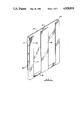
- FIG. 1 is an isometric view of the first embodiment of the invention.
- FIG. 2 is an isometric view of a second embodiment to the invention.
- FIG. 3 is top plan view of the embodiment of FIG. 2.
- FIG. 4 is an isometric view of the embodiment of FIG. 2 in use for storing compact disks.
- the storage device of FIG. 1 comprises a support plate 10 in the form of a square flat plate formed of a thin plastics material which is preferably transparent and of sufficient rigidity to hold the unit and particularly the support member flat and self supporting.
- Three side walls 11, 12 and 13 are provided with the first indicated at 11 arranged along one side of the square support member 10 and the third side wall 13 arranged along the opposed side of the support member 10.
- the second of the side walls is arranged directly along the centre line of the support member.
- Each of the side walls is parallel to the others and all extend at right angles to the support member 10.
- each of the side walls is arranged in the order of 0.5 inches.
- the outer edge or each of the side walls is formed a flange member which extends parallel to the support member 10.
- the side wall 11 thus has a flange member 14 extending inwardly across the upper surface member 10.
- the side wall 13 similarly has a flange member 15 which projects inwardly towards the flange member 14.
- flange member 16 In between the flange members 14 and 15 is provided flange member 16 of double width relative to the flange members 14 and 15 and which bridges the outer edge of the side wall 12 with portions extending in either direction. It is appreciated therefore that the flange members 14 and 16 define with the side walls 11 and 12 a slot shaped channel with a central opening 17.
- the length of the slot shaped opening of the channel is of the order of six inches with a width slightly less than 0.5 inches which is sufficient to receive a packaged compact disk which can slide along the channel.
- the lower end of the channel opposite the-open end at the upper side of the support member 10 is closed by a flat end face 18 which is connected to the support member 10 and extends outwardly therefrom a right angles and is also connected to the side walls 11, 12 and 13 together with the flange members 14, 16 and 15.
- the unit thus provides or forms an integral member which has a front face and a rear face both of which are square in plan view and have sides substantially equal to twelve inches in length.
- the thickness of the containers of the order of 0.5 inches so that it simulates the size of a conventional twelve inch record which is as is well known is generally stored in a square cardboard container with a thickness of the order of one-quarter inch.
- Each channel defined on one side of the support member 10 can receive two compact disks which slide downward into the channel and sit one on top of the other confined in the channel.
- the side wall 11 carries a label 20 which has spaces defined on the label for receiving written indicia cataloguing the four compact disks stored on the container.
- FIGS. 2 and 3 it will be appreciated that the embodiment shown in these figures is substantially the same as that shown in FIG. 1 except that it has channels formed on both sides of the support member 10A.
- the label indicated at 20A is of course modified to receive sufficient spaces for the indicia relating to eight compact disks so that each can be catalogued on the end face.
- the end face 18A has a pair of recessed cut outs 25 and 26 each cooperating with a respective one of the channels.
- the recess acts a finger recess so that the user can insert his finger into the recess and lift lowermost one of the stored compact disks out of the respective channel.
- the container shown in FIGS. 2 and 3 is sized to receive eight compact disks, its width is of the order of one inch that is double the width of the container shown in FIG. 1.
- the structure is again substantially rigid so that it can be grasped at one edge and inserted into a vertical position along side like containers or along side conventional twelve inch disks.
- FIG. 4 shown schematically one of the containers indicated at 30 including compact disks 31, 32, 33 and 34 with a label 35 on the outermost faces of the container.
- the container is stored in a furniture structure 36 along side a plurality of conventional twelve inch records indicated at 37. It will be appreciated that further conventional records can be inserted into the furniture structure 30.
- the furniture structure can contain solely containers of the type shown in FIGS. 1 or 2.
- the containers of the present invention thus enable compact disks to be stored in an effectively catalogued manner in conventional furniture dimensioned to receive the conventional twelve inch disk.
Landscapes
- Packaging For Recording Disks (AREA)
Abstract
A container for compact disks comprises a structure which is generally square in plan of twelve inch side length with a thickness substantially less than the dimension of the side and generally either 0.5 inches or 1.0 inches so that the container can be stored along side like containers or along side conventional twelve records in a furniture unit designed to receive conventional twelve inch records. The container receives the compacts disks in two channels defined along one side of the a flat plate defined in the container. Thus four compact disks can be received on one side of the plate with two in each of two channels with the channels being open along one side of the plate and closed at the other end by a flat surface projecting outwardly from the plate.
Description
This invention relates to a container for storing compact disks.
Compacts disks have become very popular in recent years in view of the high quality sound reproduction and their resistance to damage and other mistreatment. Sound recordings therefore are now available on three difference mediums, that is the somewhat oldfashioned conventional twelve inch disk, the tape cassette and the compact disk or laser disk. Storage of these different types of record of course requires entirely different storage equipment.
Conventionally, twelve inch records have been stored side by side in vertical arrangement generally in furniture which is shaped to receive the twelve inch record. Various holders are available for cassette tapes or they can simply be stacked on top of another.
Attention has been given to the storage of compact disks and various different designs of equipment and furniture have been developed for storing such disks. Examples are shown in U.S. Pat. Nos. 4,741,438 and 4,790,926 (Mastronardo), 4,655,345 (Drake), 4,762,225 (Henkel), 4,807,749 and 4,747,484 (Ackerat).
In all these devices the disks are stored side by side generally inserted into slots defined in a rectangular housing resulting in a unit which is approximately five inches by five inches with a length or height which is dependent upon the number of disks stored. Henkel discloses a foldable system which defines a number of pockets of very limited storage capacity. However storage in a device -of this type provides a resultant unit which is not very convenient and must merely rest upon suitable surface of the furniture.
Much furniture designed in the past and still used by record collectors is dimensioned to receive twelve inch records and has a number of shelves and compartments for receiving such twelve inch records. However these shelves are not suitable for receiving the container described above since much space is wasted and the resultant appearance is makeshift and unattractive.
It is one object of the present invention, therefore, to provide a container for compact disks which improves the storage of compact disks.
It is a further object of the present invention to provide a storage unit for compact disks which enables them to be stored conveniently with existing twelve inch records.
It is a yet further object of the present invention to provide a storage device for compact disks which enable the disks to be readily accessible and available for inspection of the disks stored in a comprehensive library of the disks.
According to the invention, therefore, there is provided a container for storing compact disks comprising a planar support member which is square in plan defining four sides each substantially equal to twelve inches in length, and receiving means mounted on at least one side of the support member for receiving a plurality of said compact disks, said receiving means being shaped to receive said compact disks mounted parallel to the support member and so as to confine said compact disks so as to lie spaced apart on and within the square face of the support member, said container being self-supporting and thin so as to simulate the size of a conventional twelve inch record.
The unit in which the compact disks are stored is therefore a substantially flat element which is shaped to simulate a twelve inch record so that the flat element containing four or eight of the compact disks can be inserted with conventional records or in place of conventional records in an existing furniture unit.
With the foregoing in view, and other advantages as will become apparent to those skilled in the art to which this invention relates as this specification proceeds, the invention is herein described by reference to the accompanying drawings forming a part hereof, which includes a description of the best mode known to the application and of the preferred typical embodiment of the principles of the present invention, in which:
FIG. 1 is an isometric view of the first embodiment of the invention.
FIG. 2 is an isometric view of a second embodiment to the invention.
FIG. 3 is top plan view of the embodiment of FIG. 2.
FIG. 4 is an isometric view of the embodiment of FIG. 2 in use for storing compact disks.
In the drawings like characters of reference indicate corresponding parts in the different figures.
The storage device of FIG. 1 comprises a support plate 10 in the form of a square flat plate formed of a thin plastics material which is preferably transparent and of sufficient rigidity to hold the unit and particularly the support member flat and self supporting. Three side walls 11, 12 and 13 are provided with the first indicated at 11 arranged along one side of the square support member 10 and the third side wall 13 arranged along the opposed side of the support member 10. The second of the side walls is arranged directly along the centre line of the support member. Each of the side walls is parallel to the others and all extend at right angles to the support member 10.
The height of each of the side walls is arranged in the order of 0.5 inches. The outer edge or each of the side walls is formed a flange member which extends parallel to the support member 10. The side wall 11 thus has a flange member 14 extending inwardly across the upper surface member 10. The side wall 13 similarly has a flange member 15 which projects inwardly towards the flange member 14. In between the flange members 14 and 15 is provided flange member 16 of double width relative to the flange members 14 and 15 and which bridges the outer edge of the side wall 12 with portions extending in either direction. It is appreciated therefore that the flange members 14 and 16 define with the side walls 11 and 12 a slot shaped channel with a central opening 17.
With the sides of the support member 10 being of the order of twelve inches, the length of the slot shaped opening of the channel is of the order of six inches with a width slightly less than 0.5 inches which is sufficient to receive a packaged compact disk which can slide along the channel. The lower end of the channel opposite the-open end at the upper side of the support member 10 is closed by a flat end face 18 which is connected to the support member 10 and extends outwardly therefrom a right angles and is also connected to the side walls 11, 12 and 13 together with the flange members 14, 16 and 15.
The unit thus provides or forms an integral member which has a front face and a rear face both of which are square in plan view and have sides substantially equal to twelve inches in length. The thickness of the containers of the order of 0.5 inches so that it simulates the size of a conventional twelve inch record which is as is well known is generally stored in a square cardboard container with a thickness of the order of one-quarter inch.
Each channel defined on one side of the support member 10 can receive two compact disks which slide downward into the channel and sit one on top of the other confined in the channel.
One outer face of the a side wall, in this case the side wall 11 carries a label 20 which has spaces defined on the label for receiving written indicia cataloguing the four compact disks stored on the container.
Turning now to FIGS. 2 and 3, it will be appreciated that the embodiment shown in these figures is substantially the same as that shown in FIG. 1 except that it has channels formed on both sides of the support member 10A. Thus in this case there are defined four channels 21, 22, 23 and 24 each of which can receive two compact disks as previously described. The label indicated at 20A is of course modified to receive sufficient spaces for the indicia relating to eight compact disks so that each can be catalogued on the end face. In this case the end face 18A has a pair of recessed cut outs 25 and 26 each cooperating with a respective one of the channels. The recess acts a finger recess so that the user can insert his finger into the recess and lift lowermost one of the stored compact disks out of the respective channel.
As the container shown in FIGS. 2 and 3 is sized to receive eight compact disks, its width is of the order of one inch that is double the width of the container shown in FIG. 1. The structure is again substantially rigid so that it can be grasped at one edge and inserted into a vertical position along side like containers or along side conventional twelve inch disks.
In FIG. 4 shown schematically one of the containers indicated at 30 including compact disks 31, 32, 33 and 34 with a label 35 on the outermost faces of the container. The container is stored in a furniture structure 36 along side a plurality of conventional twelve inch records indicated at 37. It will be appreciated that further conventional records can be inserted into the furniture structure 30. Alternatively, the furniture structure can contain solely containers of the type shown in FIGS. 1 or 2.
The containers of the present invention thus enable compact disks to be stored in an effectively catalogued manner in conventional furniture dimensioned to receive the conventional twelve inch disk.
Since various modifications can be made in my invention as hereinabove described, and many apparently widely different embodiments of same made within the spirit and scope of the claims without departing from such spirit and scope, it is intended that all matter contained in the accompanying specification shall be interpreted as illustrative only and not in a limiting sense.
Claims (19)
1. A container for storing compact disks comprising a planar support member which is square in plan defining four sides each substantially equal to twelve inches in length, and receiving means mounted on at least one side of the support member for receiving a plurality of said compact disks, said receiving means being shaped to receive said compact disks mounted parallel to the support member and so as to confine said compact disks to lie spaced apart on and within the square face of the support member, said container being self-supporting and thin so as to simulate the size of a conventional twelve inch record.
2. The invention according to claim 1 wherein the receiving means comprises means defining a pair of parallel channels on said one surface, said channels having one open end at one side of said support member and being shaped to receive a compact disk slideable therealong from said one open end into the channel.
3. The invention according to claim 2 wherein each of the channels has a length sufficient to receive two compact disks in end to end relationship.
4. The invention according to claim 2 wherein each of the channels is defined by a pair of side walls arranged in parallel spaced relation with each side wall projecting outwardly from the support member at right angles thereto and a pair of flanges each lying parallel to support member at a position spaced therefrom and carried by outer edges of the side walls.
5. The invention according to claim 2 wherein each of the channels includes an end face closing an end of the channel opposite to said open end.
6. The invention according to claim 5 wherein each of the end faces includes a recess in one edge thereof.
7. The invention according to claim 1 wherein each side of said support member includes receiving means thereon.
8. The invention according to claim 1 wherein said receiving means defines an end face of the support member at right angles to the support member and lying in a plane of one edge of the support member, the end face having mounted thereon a label for receiving written information identifying the compact disks stored in the container.
9. The invention according to claim 1 wherein the thickness of the container is less than one inch.
10. A container for compact disks comprising a container body having a plurality of receptacles for receiving said compact disks, said body having a front and a rear face the outer periphery of which in plan are square with sides substantially equal to twelve inches and four edge surfaces each of which has a width less than the order of one inch, the container being self supporting so that it can be lifted at one edge and inserted into a stack-of like containers.
11. The invention according to claim 10 wherein the receptacles comprise means defining a pair of parallel channels on said one surface, said channels having one open end at one side of said container body and being shaped to receive a compact disk slideable therealong from said one open end into the channel.
12. The invention according to claim 11 wherein each of the channels has a length sufficient to receive two compact disks in end to end relationship.
13. The invention according to claim 11 wherein each of the channels is defined by a pair of side walls arranged in parallel spaced relation with each side wall projecting from the container body at right angles thereto and a pair of flanges each lying parallel to support member at a position spaced therefrom and carried by outer edges of the side walls.
14. The invention according to claim 11 wherein each of the channels includes an end face closing an end of the channel opposite to said open end.
15. The invention according to claim 14 wherein each of the end faces includes a recess in one edge thereof.
16. The invention according to claim 11 wherein each side of said container body includes receptacles thereon.
17. The invention according to claim 1 wherein one edge surface of the container body has mounted thereon a label for receiving written information identifying the compact disks stored in the container body.
18. The invention according to claim 1 wherein the thickness of the container body is less than 0.5 inches.
19. A container for storing compact disks comprising a planar support member which is square in plan defining four sides each substantially equal to twelve inches in length, a first, a second and a third side wall extending in parallel spaced relation across the support member and at right angles to the support member, the first and third side walls being arranged at opposed sides of the support member and the second side wall being arranged half way across the support member, and flange means mounted at the edge of the side walls remote from the support member and projecting parallel to the support member so that the flange means, side walls, and support member define two parallel channels having one end of each channel open at a side of the support member, an end face member closing an opposed end of each of the channels, each of the side walls having a width of the order of one-half inch, the container being substantially self-supporting so as to simulate the size and structure of a convention twelve inch record and such that the container can be inserted into a stack including twelve inch records and like containers.
Priority Applications (1)
| Application Number | Priority Date | Filing Date | Title |
|---|---|---|---|
| US07/399,027 US4928818A (en) | 1989-08-28 | 1989-08-28 | Container for compact disks |
Applications Claiming Priority (1)
| Application Number | Priority Date | Filing Date | Title |
|---|---|---|---|
| US07/399,027 US4928818A (en) | 1989-08-28 | 1989-08-28 | Container for compact disks |
Publications (1)
| Publication Number | Publication Date |
|---|---|
| US4928818A true US4928818A (en) | 1990-05-29 |
Family
ID=23577828
Family Applications (1)
| Application Number | Title | Priority Date | Filing Date |
|---|---|---|---|
| US07/399,027 Expired - Fee Related US4928818A (en) | 1989-08-28 | 1989-08-28 | Container for compact disks |
Country Status (1)
| Country | Link |
|---|---|
| US (1) | US4928818A (en) |
Cited By (16)
| Publication number | Priority date | Publication date | Assignee | Title |
|---|---|---|---|---|
| US5105952A (en) * | 1991-03-04 | 1992-04-21 | Krattiger Donald G | Compact disc storage and display device |
| US5201414A (en) * | 1992-05-11 | 1993-04-13 | Kaszubinski Richard R | Compact disc storage apparatus |
| WO1994018095A1 (en) * | 1993-02-04 | 1994-08-18 | Yoshihiko Taniyama | Expandable storage container system |
| US5363956A (en) * | 1993-02-22 | 1994-11-15 | Yoshihiko Taniyama | Container for plurality of stackable objects |
| US5388713A (en) * | 1993-04-14 | 1995-02-14 | Taniyama; Yoshihiko | Storage container |
| US5458236A (en) * | 1993-01-18 | 1995-10-17 | Basf Magnetics Gmbh | Container, substantially of cuboid form, for at least two articles |
| US5560481A (en) * | 1991-05-16 | 1996-10-01 | U.S. Philips Corporation | Holder for a rectangular cassette |
| USD375429S (en) | 1995-04-28 | 1996-11-12 | New Plastics, Inc. | Floppy disc holder |
| US5593032A (en) * | 1995-03-23 | 1997-01-14 | Staley; Leland | Disc retainer device |
| USD386915S (en) * | 1996-04-05 | 1997-12-02 | Sony Kabushiki Kaisha | Audio cassette tape case |
| US6431354B1 (en) * | 2000-11-07 | 2002-08-13 | Sanriki Kogyo Kabushiki Kaisha | Picture frame type cover for disk storage case |
| US6533128B1 (en) | 2002-02-04 | 2003-03-18 | James M. Beneway | Holder for storage boxes |
| US20030168235A1 (en) * | 2002-03-07 | 2003-09-11 | Todd Loeffelholz | EMI shielded module |
| USD480579S1 (en) | 2002-04-22 | 2003-10-14 | Glenn Hillman | Modular CD holder |
| US20070210097A1 (en) * | 2006-03-07 | 2007-09-13 | Mesalic Admir J | Cartridge based dispenser system and method |
| USD637649S1 (en) * | 2010-06-08 | 2011-05-10 | Steelcase Inc. | Combined holder and divider |
Citations (10)
| Publication number | Priority date | Publication date | Assignee | Title |
|---|---|---|---|---|
| US4235490A (en) * | 1978-12-26 | 1980-11-25 | Le-Bo Products Company, Inc. | Video cassette storage and ejection device |
| US4432453A (en) * | 1982-09-30 | 1984-02-21 | Berkman Industries, Inc. | Storage system for either boxed or unboxed cassettes |
| US4511194A (en) * | 1982-03-26 | 1985-04-16 | U.S. Philips Corporation | Magazine and disc holders for supporting discs in the magazine |
| US4577914A (en) * | 1984-05-16 | 1986-03-25 | Stravitz David M | Assembly of slidably interfitting storage units |
| US4655345A (en) * | 1985-11-14 | 1987-04-07 | Drake Craig D | Compact disc storage unit |
| US4741438A (en) * | 1986-07-21 | 1988-05-03 | Patrick Mastronardo | Dual and single audio disc box storage tray |
| US4747484A (en) * | 1986-01-30 | 1988-05-31 | Idn Invention And Development Of Novelties Ag | Container for video and sound recording media |
| US4762225A (en) * | 1986-08-28 | 1988-08-09 | Henkel Walter R | Compact disc guard and carrying system |
| US4781292A (en) * | 1986-04-04 | 1988-11-01 | Sacherman James E | Storage rack for compact discs, cassettes and the like |
| US4807749A (en) * | 1984-08-02 | 1989-02-28 | Idn Inventions And Development Of Novelties Ag | Container for flat recording media |
-
1989
- 1989-08-28 US US07/399,027 patent/US4928818A/en not_active Expired - Fee Related
Patent Citations (11)
| Publication number | Priority date | Publication date | Assignee | Title |
|---|---|---|---|---|
| US4235490A (en) * | 1978-12-26 | 1980-11-25 | Le-Bo Products Company, Inc. | Video cassette storage and ejection device |
| US4511194A (en) * | 1982-03-26 | 1985-04-16 | U.S. Philips Corporation | Magazine and disc holders for supporting discs in the magazine |
| US4432453A (en) * | 1982-09-30 | 1984-02-21 | Berkman Industries, Inc. | Storage system for either boxed or unboxed cassettes |
| US4577914A (en) * | 1984-05-16 | 1986-03-25 | Stravitz David M | Assembly of slidably interfitting storage units |
| US4807749A (en) * | 1984-08-02 | 1989-02-28 | Idn Inventions And Development Of Novelties Ag | Container for flat recording media |
| US4655345A (en) * | 1985-11-14 | 1987-04-07 | Drake Craig D | Compact disc storage unit |
| US4747484A (en) * | 1986-01-30 | 1988-05-31 | Idn Invention And Development Of Novelties Ag | Container for video and sound recording media |
| US4781292A (en) * | 1986-04-04 | 1988-11-01 | Sacherman James E | Storage rack for compact discs, cassettes and the like |
| US4741438A (en) * | 1986-07-21 | 1988-05-03 | Patrick Mastronardo | Dual and single audio disc box storage tray |
| US4790926A (en) * | 1986-07-21 | 1988-12-13 | Patrick Mastronardo | Dual and single audio disc box storage tray |
| US4762225A (en) * | 1986-08-28 | 1988-08-09 | Henkel Walter R | Compact disc guard and carrying system |
Cited By (20)
| Publication number | Priority date | Publication date | Assignee | Title |
|---|---|---|---|---|
| US5105952A (en) * | 1991-03-04 | 1992-04-21 | Krattiger Donald G | Compact disc storage and display device |
| WO1992015234A1 (en) * | 1991-03-04 | 1992-09-17 | Krattiger Donald G | Compact disc storage and display device |
| US5560481A (en) * | 1991-05-16 | 1996-10-01 | U.S. Philips Corporation | Holder for a rectangular cassette |
| US5201414A (en) * | 1992-05-11 | 1993-04-13 | Kaszubinski Richard R | Compact disc storage apparatus |
| US5458236A (en) * | 1993-01-18 | 1995-10-17 | Basf Magnetics Gmbh | Container, substantially of cuboid form, for at least two articles |
| WO1994018095A1 (en) * | 1993-02-04 | 1994-08-18 | Yoshihiko Taniyama | Expandable storage container system |
| US5392906A (en) * | 1993-02-04 | 1995-02-28 | Taniyama; Yoshihiko | Expandable storage container system |
| US5363956A (en) * | 1993-02-22 | 1994-11-15 | Yoshihiko Taniyama | Container for plurality of stackable objects |
| US5388713A (en) * | 1993-04-14 | 1995-02-14 | Taniyama; Yoshihiko | Storage container |
| US5593032A (en) * | 1995-03-23 | 1997-01-14 | Staley; Leland | Disc retainer device |
| USD375429S (en) | 1995-04-28 | 1996-11-12 | New Plastics, Inc. | Floppy disc holder |
| USD386915S (en) * | 1996-04-05 | 1997-12-02 | Sony Kabushiki Kaisha | Audio cassette tape case |
| US6431354B1 (en) * | 2000-11-07 | 2002-08-13 | Sanriki Kogyo Kabushiki Kaisha | Picture frame type cover for disk storage case |
| US6533128B1 (en) | 2002-02-04 | 2003-03-18 | James M. Beneway | Holder for storage boxes |
| US20030168235A1 (en) * | 2002-03-07 | 2003-09-11 | Todd Loeffelholz | EMI shielded module |
| US20060005981A1 (en) * | 2002-03-07 | 2006-01-12 | Adc Telecommunications, Inc. | Emi shielded module |
| US7705248B2 (en) | 2002-03-07 | 2010-04-27 | Atx Networks Corp. | EMI shielded module |
| USD480579S1 (en) | 2002-04-22 | 2003-10-14 | Glenn Hillman | Modular CD holder |
| US20070210097A1 (en) * | 2006-03-07 | 2007-09-13 | Mesalic Admir J | Cartridge based dispenser system and method |
| USD637649S1 (en) * | 2010-06-08 | 2011-05-10 | Steelcase Inc. | Combined holder and divider |
Similar Documents
| Publication | Publication Date | Title |
|---|---|---|
| US4928818A (en) | Container for compact disks | |
| US3710900A (en) | Modular system for transporting and storing tape cartridges and cassettes | |
| US5285893A (en) | Storage case for multiple compact discs and related printed material | |
| US4676374A (en) | Hard case floppy disk holder | |
| US5697498A (en) | Carrying case for recorded media | |
| US4823950A (en) | Storage arrangement for optical discs and their containers | |
| US5040687A (en) | Wall-mounted compact disc display | |
| US4453785A (en) | Modular cabinet for different video game cartridges, cassettes, and instruction booklets | |
| EP0886861B1 (en) | Detachable module disc and flat object storage system | |
| US5794796A (en) | Storage rack for retaining software devices having multiple configurations | |
| US4819801A (en) | Storage case | |
| US5474170A (en) | CD holder and display array | |
| WO1993011538A1 (en) | Compact disc holder | |
| US4231473A (en) | Dual purpose insert for tape cartridges and cassettes | |
| US5988405A (en) | Wall unit for displaying the covers of multiple media cases | |
| US5685423A (en) | Mixed media storage tray | |
| US6340086B1 (en) | Media storage apparatus | |
| US6082553A (en) | Stepped organizer/rack | |
| US7066325B2 (en) | Storage container for recorded media | |
| US3921811A (en) | Media holders for bookshelves | |
| US4723662A (en) | Article storage rack | |
| US4367000A (en) | Display apparatus | |
| US5445269A (en) | Media storage bin | |
| US6206184B1 (en) | Multimedia distribution package | |
| GB2162826A (en) | Case for magnetic recording medium |
Legal Events
| Date | Code | Title | Description |
|---|---|---|---|
| LAPS | Lapse for failure to pay maintenance fees | ||
| FP | Expired due to failure to pay maintenance fee |
Effective date: 19940529 |
|
| STCH | Information on status: patent discontinuation |
Free format text: PATENT EXPIRED DUE TO NONPAYMENT OF MAINTENANCE FEES UNDER 37 CFR 1.362 |