US4918585A - Maintenance reminder system for a pump - Google Patents
Maintenance reminder system for a pump Download PDFInfo
- Publication number
- US4918585A US4918585A US07/142,371 US14237188A US4918585A US 4918585 A US4918585 A US 4918585A US 14237188 A US14237188 A US 14237188A US 4918585 A US4918585 A US 4918585A
- Authority
- US
- United States
- Prior art keywords
- maintenance
- pump
- pumped
- threshold
- volume
- Prior art date
- Legal status (The legal status is an assumption and is not a legal conclusion. Google has not performed a legal analysis and makes no representation as to the accuracy of the status listed.)
- Expired - Fee Related
Links
Images


Classifications
-
- F—MECHANICAL ENGINEERING; LIGHTING; HEATING; WEAPONS; BLASTING
- F04—POSITIVE - DISPLACEMENT MACHINES FOR LIQUIDS; PUMPS FOR LIQUIDS OR ELASTIC FLUIDS
- F04B—POSITIVE-DISPLACEMENT MACHINES FOR LIQUIDS; PUMPS
- F04B51/00—Testing machines, pumps, or pumping installations
-
- F—MECHANICAL ENGINEERING; LIGHTING; HEATING; WEAPONS; BLASTING
- F04—POSITIVE - DISPLACEMENT MACHINES FOR LIQUIDS; PUMPS FOR LIQUIDS OR ELASTIC FLUIDS
- F04B—POSITIVE-DISPLACEMENT MACHINES FOR LIQUIDS; PUMPS
- F04B49/00—Control, e.g. of pump delivery, or pump pressure of, or safety measures for, machines, pumps, or pumping installations, not otherwise provided for, or of interest apart from, groups F04B1/00 - F04B47/00
-
- G—PHYSICS
- G01—MEASURING; TESTING
- G01N—INVESTIGATING OR ANALYSING MATERIALS BY DETERMINING THEIR CHEMICAL OR PHYSICAL PROPERTIES
- G01N30/00—Investigating or analysing materials by separation into components using adsorption, absorption or similar phenomena or using ion-exchange, e.g. chromatography or field flow fractionation
- G01N30/02—Column chromatography
- G01N30/26—Conditioning of the fluid carrier; Flow patterns
- G01N30/28—Control of physical parameters of the fluid carrier
- G01N30/32—Control of physical parameters of the fluid carrier of pressure or speed
-
- F—MECHANICAL ENGINEERING; LIGHTING; HEATING; WEAPONS; BLASTING
- F04—POSITIVE - DISPLACEMENT MACHINES FOR LIQUIDS; PUMPS FOR LIQUIDS OR ELASTIC FLUIDS
- F04B—POSITIVE-DISPLACEMENT MACHINES FOR LIQUIDS; PUMPS
- F04B2201/00—Pump parameters
- F04B2201/02—Piston parameters
- F04B2201/0207—Number of pumping strokes in unit time
-
- F—MECHANICAL ENGINEERING; LIGHTING; HEATING; WEAPONS; BLASTING
- F04—POSITIVE - DISPLACEMENT MACHINES FOR LIQUIDS; PUMPS FOR LIQUIDS OR ELASTIC FLUIDS
- F04B—POSITIVE-DISPLACEMENT MACHINES FOR LIQUIDS; PUMPS
- F04B2201/00—Pump parameters
- F04B2201/12—Parameters of driving or driven means
- F04B2201/1208—Angular position of the shaft
-
- F—MECHANICAL ENGINEERING; LIGHTING; HEATING; WEAPONS; BLASTING
- F04—POSITIVE - DISPLACEMENT MACHINES FOR LIQUIDS; PUMPS FOR LIQUIDS OR ELASTIC FLUIDS
- F04B—POSITIVE-DISPLACEMENT MACHINES FOR LIQUIDS; PUMPS
- F04B2205/00—Fluid parameters
- F04B2205/05—Pressure after the pump outlet
-
- F—MECHANICAL ENGINEERING; LIGHTING; HEATING; WEAPONS; BLASTING
- F04—POSITIVE - DISPLACEMENT MACHINES FOR LIQUIDS; PUMPS FOR LIQUIDS OR ELASTIC FLUIDS
- F04B—POSITIVE-DISPLACEMENT MACHINES FOR LIQUIDS; PUMPS
- F04B2207/00—External parameters
- F04B2207/04—Settings
- F04B2207/041—Settings of flow
-
- F—MECHANICAL ENGINEERING; LIGHTING; HEATING; WEAPONS; BLASTING
- F04—POSITIVE - DISPLACEMENT MACHINES FOR LIQUIDS; PUMPS FOR LIQUIDS OR ELASTIC FLUIDS
- F04B—POSITIVE-DISPLACEMENT MACHINES FOR LIQUIDS; PUMPS
- F04B2207/00—External parameters
- F04B2207/04—Settings
- F04B2207/042—Settings of pressure
-
- G—PHYSICS
- G01—MEASURING; TESTING
- G01N—INVESTIGATING OR ANALYSING MATERIALS BY DETERMINING THEIR CHEMICAL OR PHYSICAL PROPERTIES
- G01N30/00—Investigating or analysing materials by separation into components using adsorption, absorption or similar phenomena or using ion-exchange, e.g. chromatography or field flow fractionation
- G01N30/02—Column chromatography
- G01N30/26—Conditioning of the fluid carrier; Flow patterns
- G01N30/28—Control of physical parameters of the fluid carrier
- G01N30/32—Control of physical parameters of the fluid carrier of pressure or speed
- G01N2030/326—Control of physical parameters of the fluid carrier of pressure or speed pumps
-
- G—PHYSICS
- G01—MEASURING; TESTING
- G01N—INVESTIGATING OR ANALYSING MATERIALS BY DETERMINING THEIR CHEMICAL OR PHYSICAL PROPERTIES
- G01N30/00—Investigating or analysing materials by separation into components using adsorption, absorption or similar phenomena or using ion-exchange, e.g. chromatography or field flow fractionation
- G01N30/02—Column chromatography
- G01N30/88—Integrated analysis systems specially adapted therefor, not covered by a single one of the groups G01N30/04 - G01N30/86
- G01N2030/8804—Integrated analysis systems specially adapted therefor, not covered by a single one of the groups G01N30/04 - G01N30/86 automated systems
Definitions
- the invention pertains to the field of liquid chromatography (hereafter LC), and, more particularly, to the field of maintenance reminder systems for the pumps of LC systems.
- LC liquid chromatography
- Pumps for LC systems must provide very reliable pumping action to allow the control system for the pump to control it in such a manner as to provide a constant flow rate of solvent through the pump.
- Such pumps involve seals which have a limited life, pistons which may become scratched and check valves which may become leaky. Since a constant flow rate is very important to LC systems and since the pressures involved are typically very high, the slightest defect in the pump can seriously impair the effectiveness of the system.
- the applicants are not aware of any systems on the market which can provide LC system users with reminders of when a maintenance inspection of invidual components of a pump should be performed.
- a maintenance reminder system for a pump.
- the invention is coupled to the control system of the pump.
- the control system provides to the apparatus of the invention a signal from which can be derived information as to when each stroke of one or more pistons in the pump has occurred.
- the control system is coupled to the shaft of the pump and to the pump motor drive system.
- An index signal is generated upon completion of each revolution of the pump shaft.
- the maintenance reminder system counts piston strokes and converts this information into liters of fluid pumped from the known displacement of each piston.
- the user may supply a threshold in terms of liters pumped for each specific element of the pump for which maintenance should be periodically performed.
- this threshold may be set at a fixed, predetermined amount for each individual element or a single threshold can be used.
- the maintenance reminder system updates non volatile RAM each time another liter is pumped, and compares the liters pumped to the threshold for each element. When the actual liters pumped since the last maintenance on any particular item equals or exceeds the threshold set for that item, a maintenance needed reminder is displayed.
- the user can, in the preferred embodiment, have more detail displayed or printed as to the status of all the items, and this display will have an indication of which items are over their threshold.
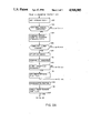
- FIG. 1 is block diagram of a typical pump control system in which the maintenance reminder system of the invention can reside.
- FIGS. 2A and 2B are a flow chart of the program that implements the maintenance reminder system.
- FIG. 1 there is shown a block diagram of a typical pump control system in which the system of the invention can find use.
- An inner loop 70 senses the actual pressure on the outlet line 24 to the column via a pressure transducer 72 and uses the actual pressure signal from the transducer on line 74 as one input to a differential amplifier 76. The other input to this amplifier is the target pressure signal on line 78 from an outer loop 88. These two signals are compared to generate an error signal on line 80.
- the error signal is coupled to the motor driver and motor 82 and controls the motor speed.
- the motor drives a shaft 84 which drives the pump 86.
- the outer loop 88 senses the shaft speed via a shaft encoder or other device 90.
- the shaft encoder generates a signal used by a computer 92 to determine the pump speed and to determine the flow rate of solvent in the output line 24.
- the computer also receives a desired flow rate signal on line 94 and uses this signal to compare to the actual flow rate as indicated by the signal from the shaft encoder to set a target pressure signal on line 78 to correct the actual flow rate toward the desired flow rate.
- the shaft encoder also provides data regarding the absolute shaft position relative to an index point. This data provides the computer with real time information as to the actual position of each of the cams in the pump 86 and the status of the pistons of the pump at each point in time. An index point is in the rotation of the shaft 84 defined which defines a known position of the cams and the pistons.
- the pump is driven by a stepper motor 82.
- the steps of the stopper motor 82 translate to known translations of the shaft 84.
- the computer is coupled to the motor driver through the line 91 so that the steps can be counted and the shaft position at any point in time may be known.
- the computer 92 is also coupled to a display 100 and to non volatile RAM 102, which, in the preferred embodiment, is EEPROM.
- the maintenance reminder system of the invention is implemented by a program run by the computer 92.
- the computer 92 also runs a pump control program to generate the target pressure signal from the computed shaft speed of the pump and the desired flow rate supplied on line 94.
- Part of this pump control program is a housekeeping routine which takes care of miscellaneous functions most of which are irrelevant to the teachings of the invention.
- Part of the function of the maintenance reminder system is to check a maintenance due flag which is set by the main program of the maintenance reminder system when some element of the pump has reached or exceeded its maintenance threshold.
- the maintenance reminder system is a subroutine of the housekeeping routine, but it may be a stand alone program in other embodiments.
- the first step in the program to perform the maintenance reminder task is to get the stroke count as symbolized by step 120.
- This step symbolizes any routine to count the strokes.
- there may be a counter in the main pump control program (not shown) which increments each time an index signal occurs indicating another revolution has been completed.
- the step 120 may symbolize an interrupt service routine which is performed each time the index signal occurs and which increments a counter.
- the next step 122 represents a test as to whether another stroke has been completed. It may be eliminated in embodiments wherein the step 120 is not reached until it is known that another stroke has been completed such as embodiments which service an interrupt generated upon the occurrence of the index signal. For embodiments where the stroke count is kept in a separate counter and where step 120 represents the process of getting the count from that counter, the test 122 represents the process of comparing the old count and the new count to determine if another stroke has been completed. If not, control is returned to the housekeeping routine which then goes about its other business. If another stroke has been completed, step 124 is performed.
- Step 124 represents the process of comparing the stroke count (if the embodiment of FIG. 2 represents an interrupt service routine, a stroke counter will be incremented as part of step 124) to a constant equal to the number of strokes per liter.
- step 126 is performed. The purpose of this step is to determine whether a complete liter has been pumped because the non volatile RAM is updated only after a complete liter has been pumped. In alternative embodiments, the memory may be updated on every stroke or after a predetermined number of strokes. Step 126 symbolizes whatever comparison is necessary to determine whether a complete liter has been pumped since the last update of the database.
- step 128 updates the data base.
- Each item which need periodic maintenance in the pump has a database record which contains at least two fields and preferably four fields.
- the database record for each maintenance item contains a field for the threshold in terms of the whole number of liters that may be pumped between maintenance operations for that item. In the preferred embodiment, this field is user accessible and may be changed by the user. Another field stores the actual number of liters that have been pumped since the last maintenance on that item. It is this field which is updated by incrementation in step 128.
- the database also has a third field which used in the case of power failures and which stores the fractional number of liters which have been pumped since the last update. Although the steps to do this update upon a power failure are not shown in the flow chart of FIG. 2, it should be understood that the teachings of the invention contemplate such a function in some embodiments.
- a fourth field of the data base is the date the last maintenance was performed.
- Step 130 is performed to compare the actual liters pumped since the last maintenance for each item to the threshold for that item.
- Step 132 represents a check to determine if any item's threshold has been exceeded. If not, control is returned to the housekeeping routine. If a threshold has been exceeded, step 134 sets a maintenance due flag. Control is then returned to the housekeeping routine.
- the housekeeping routine symbolized by clock 136 checks the maintenance due flag upon the occurrence of either of two events in the preferred embodiment. These events are pump initialization upon start up for a new run and upon the passage of approximately 10 hours from the last check of the maintenance due flag. In other embodiments, the maintenance due flag may be checked periodically or upon the occurrence of different or more events. These checks are symbolized by block 138. Processing then proceeds to step 140 via line 139.
- Step 140 is a test to determine if the maintenance due flag is set. If it is not set, control is returned to the housekeeping routine. If it is set, step 142 is performed to display a maintenance due message.
- the next step would be to automatically display the details of the database for all the maintenance items and highlight the items needing maintenance or to display the database fields for those items needing maintenance.
- step 144 if performed to determine is the user is requesting more detail. In some embodiments, this may be done by a display prompt asking the user if more detail is requested and monitoring a keyboard or some switch for a predetermined response. In other embodiments, step 144 may represent an interrupt vector generated when the user requests more detail.
- step 146 is performed to prompt the user to determine if the data is to be displayed or printed. If the user selects the print option, all the database records or the records for selected items are printed as symbolized by step 148. If the display option is selected, all the database records or selected ones of them are displayed as symbolized by block 150. Control is then returned to the housekeeping routine.
- Step 152 represents the step of monitoring when the user performs the required maintenance.
- the user accesses the data base and enters the date of performing the maintenance in the appropriate field of the database record for the item serviced.
- Step 152 represents the process of enabling the user to enter the database and make this entry or, in alternative embodiments, symbolizes the process of prompting the user for the identification of the item serviced and the data of the service.
- Step 154 is then performed to zero the "liters pumped since last maintenance" field of the appropriate item in the preferred embodiment. In alternate “prompting" embodiments, step 154 also represents the step of updating the "date of last maintenance" field.
- system of the invention could be adapted to a turbine type pump with modifications to allow the pump maintenance system to detect the flow rate from the pump and the elapsed time at each flow rate.
- flow rate and elapsed time data could also be used in piston pump applications as described above by using the computed shaft speed and elapsed time computed by the main pump control program instead of the index signal. All such embodiments are intended to be included within the scope of the claims appended hereto.
Abstract
Description
Claims (23)
Priority Applications (1)
| Application Number | Priority Date | Filing Date | Title |
|---|---|---|---|
| US07/142,371 US4918585A (en) | 1988-01-11 | 1988-01-11 | Maintenance reminder system for a pump |
Applications Claiming Priority (1)
| Application Number | Priority Date | Filing Date | Title |
|---|---|---|---|
| US07/142,371 US4918585A (en) | 1988-01-11 | 1988-01-11 | Maintenance reminder system for a pump |
Publications (1)
| Publication Number | Publication Date |
|---|---|
| US4918585A true US4918585A (en) | 1990-04-17 |
Family
ID=22499596
Family Applications (1)
| Application Number | Title | Priority Date | Filing Date |
|---|---|---|---|
| US07/142,371 Expired - Fee Related US4918585A (en) | 1988-01-11 | 1988-01-11 | Maintenance reminder system for a pump |
Country Status (1)
| Country | Link |
|---|---|
| US (1) | US4918585A (en) |
Cited By (12)
| Publication number | Priority date | Publication date | Assignee | Title |
|---|---|---|---|---|
| FR2663690A1 (en) * | 1990-06-26 | 1991-12-27 | Cit Alcatel | DEVICE FOR PROVIDING SAFE MANAGEMENT OF A VACUUM PUMP. |
| WO1992017339A1 (en) * | 1989-12-18 | 1992-10-15 | Master Flo Technology Inc. | Liquid flow metering |
| US5195612A (en) * | 1992-05-18 | 1993-03-23 | Case Corporation | Lubrication system for a cotton harvester |
| US5287875A (en) * | 1990-11-27 | 1994-02-22 | Hitachi, Ltd. | Draining pump system and drainage preference operating method therefor |
| EP0701660A1 (en) * | 1993-06-01 | 1996-03-20 | SIPIN, Anatole J. | Motor controlled constant flow pump |
| US5581486A (en) * | 1992-11-30 | 1996-12-03 | Sony Corporation | Maintenance management system for managing maintenance of components of assembly apparatus |
| AU680906B2 (en) * | 1989-12-22 | 1997-08-14 | Avid Technology, Inc. | Media storage and retrieval system |
| WO2003040568A1 (en) * | 2001-11-09 | 2003-05-15 | Leybold Vakuum Gmbh | Vacuum pump |
| EP1404061A1 (en) * | 2001-06-22 | 2004-03-31 | Omron Corporation | Safety network system and safety slave |
| US20100262320A1 (en) * | 2009-04-14 | 2010-10-14 | Nabtesco Corporation | Actuator monitoring circuit, controller, and actuator unit |
| US9670918B2 (en) | 2013-04-12 | 2017-06-06 | Pentair Flow Technologies, Llc | Water booster control system and method |
| US11703051B2 (en) * | 2019-02-12 | 2023-07-18 | Terzo Power Systems, LLC | Valveless hydraulic system |
Citations (6)
| Publication number | Priority date | Publication date | Assignee | Title |
|---|---|---|---|---|
| US3896827A (en) * | 1973-08-31 | 1975-07-29 | Norman R Robinson | Dish machine monitoring of time, temperature, alkalinity, and pressure parameters |
| US4128476A (en) * | 1977-06-14 | 1978-12-05 | Spectra-Physics, Inc. | Carrier composition control for liquid chromatographic systems |
| US4137011A (en) * | 1977-06-14 | 1979-01-30 | Spectra-Physics, Inc. | Flow control system for liquid chromatographs |
| US4512442A (en) * | 1984-03-30 | 1985-04-23 | Westinghouse Electric Corp. | Method and apparatus for improving the servicing of an elevator system |
| US4552513A (en) * | 1983-03-07 | 1985-11-12 | Spectra-Physics, Inc. | Multiple piston pump control |
| US4752283A (en) * | 1987-02-17 | 1988-06-21 | Western Litho Plate & Supply Co. | Waste water cleaning system for use with apparatus for processing exposed lithographic plates |
-
1988
- 1988-01-11 US US07/142,371 patent/US4918585A/en not_active Expired - Fee Related
Patent Citations (6)
| Publication number | Priority date | Publication date | Assignee | Title |
|---|---|---|---|---|
| US3896827A (en) * | 1973-08-31 | 1975-07-29 | Norman R Robinson | Dish machine monitoring of time, temperature, alkalinity, and pressure parameters |
| US4128476A (en) * | 1977-06-14 | 1978-12-05 | Spectra-Physics, Inc. | Carrier composition control for liquid chromatographic systems |
| US4137011A (en) * | 1977-06-14 | 1979-01-30 | Spectra-Physics, Inc. | Flow control system for liquid chromatographs |
| US4552513A (en) * | 1983-03-07 | 1985-11-12 | Spectra-Physics, Inc. | Multiple piston pump control |
| US4512442A (en) * | 1984-03-30 | 1985-04-23 | Westinghouse Electric Corp. | Method and apparatus for improving the servicing of an elevator system |
| US4752283A (en) * | 1987-02-17 | 1988-06-21 | Western Litho Plate & Supply Co. | Waste water cleaning system for use with apparatus for processing exposed lithographic plates |
Non-Patent Citations (2)
| Title |
|---|
| Spectra Physics SP8700 Solvent Delivery System, 12 pages, published for Spectra Physics. * |
| Spectra Physics SP8700 Solvent Delivery System, 12 pages, published for Spectra-Physics. |
Cited By (19)
| Publication number | Priority date | Publication date | Assignee | Title |
|---|---|---|---|---|
| WO1992017339A1 (en) * | 1989-12-18 | 1992-10-15 | Master Flo Technology Inc. | Liquid flow metering |
| AU680906B2 (en) * | 1989-12-22 | 1997-08-14 | Avid Technology, Inc. | Media storage and retrieval system |
| EP0464571A1 (en) * | 1990-06-26 | 1992-01-08 | Alcatel Cit | Device for the safe managing of a vacuum pump |
| FR2663690A1 (en) * | 1990-06-26 | 1991-12-27 | Cit Alcatel | DEVICE FOR PROVIDING SAFE MANAGEMENT OF A VACUUM PUMP. |
| US5287875A (en) * | 1990-11-27 | 1994-02-22 | Hitachi, Ltd. | Draining pump system and drainage preference operating method therefor |
| US5195612A (en) * | 1992-05-18 | 1993-03-23 | Case Corporation | Lubrication system for a cotton harvester |
| US5581486A (en) * | 1992-11-30 | 1996-12-03 | Sony Corporation | Maintenance management system for managing maintenance of components of assembly apparatus |
| EP0701660A4 (en) * | 1993-06-01 | 1998-03-18 | Anatole J Sipin | Motor controlled constant flow pump |
| EP0701660A1 (en) * | 1993-06-01 | 1996-03-20 | SIPIN, Anatole J. | Motor controlled constant flow pump |
| EP1404061A1 (en) * | 2001-06-22 | 2004-03-31 | Omron Corporation | Safety network system and safety slave |
| EP1404061B1 (en) * | 2001-06-22 | 2011-08-10 | Omron Corporation | Safety network system and safety slave |
| WO2003040568A1 (en) * | 2001-11-09 | 2003-05-15 | Leybold Vakuum Gmbh | Vacuum pump |
| US20040260409A1 (en) * | 2001-11-09 | 2004-12-23 | Jurgen Brezina | Vacuum pump |
| US6999840B2 (en) | 2001-11-09 | 2006-02-14 | Leybold Vakuum Gmbh | Vacuum pump |
| US20100262320A1 (en) * | 2009-04-14 | 2010-10-14 | Nabtesco Corporation | Actuator monitoring circuit, controller, and actuator unit |
| US9459609B2 (en) * | 2009-04-14 | 2016-10-04 | Nabtesco Corporation | Actuator monitoring circuit, controller, and actuator unit |
| US9670918B2 (en) | 2013-04-12 | 2017-06-06 | Pentair Flow Technologies, Llc | Water booster control system and method |
| US10487813B2 (en) | 2013-04-12 | 2019-11-26 | Pentair Flow Technologies, Llc | Water booster control system and method |
| US11703051B2 (en) * | 2019-02-12 | 2023-07-18 | Terzo Power Systems, LLC | Valveless hydraulic system |
Similar Documents
| Publication | Publication Date | Title |
|---|---|---|
| US4918585A (en) | Maintenance reminder system for a pump | |
| US4998914A (en) | Procedure for the perfusion of cavities in objects and device for executing the procedure | |
| US5973662A (en) | Analog spectrum display for environmental control | |
| US7000193B1 (en) | Display to facilitate the monitoring of a complex process | |
| US5479344A (en) | Insurance computation display | |
| US20060089920A1 (en) | Method and system for evaluating costs of various design and maintenance approaches | |
| US9396592B2 (en) | Maintenance systems and methods for use in analyzing maintenance data | |
| Macgregor et al. | Optimizing the structure of database menu indexes: A decision model of menu search | |
| US20100313072A1 (en) | Failure Analysis Based on Time-Varying Failure Rates | |
| US7191367B2 (en) | Storage unit, condition monitoring program product, and condition monitoring program storage medium | |
| US7027954B2 (en) | Method and apparatus for retrieving activity data related to an activity | |
| US20190392402A1 (en) | Adaptive maintenance of a pressurized fluid cutting system | |
| CA3127100C (en) | Anomaly detection for predictive maintenance and deriving outcomes and workflows based on data quality | |
| US10600216B2 (en) | Automatic data visualization system | |
| US8285616B2 (en) | Method and system for dynamically producing detailed trade payment experience for enhancing credit evaluation | |
| AU2021299217A1 (en) | Fuel leak determination via predictive modeling | |
| US4651307A (en) | Non-volatile memory storage system | |
| US4832575A (en) | Automatic test system for check valve closure in pump for liquid chromatography system | |
| US7768530B2 (en) | Verification of process variable transmitter | |
| US4905161A (en) | Flow stability reporting system for a liquid chromatography system | |
| US8065112B2 (en) | Apparatus and method for assessing exceedance of a process beyond safe operating limits | |
| US20210350338A1 (en) | Maintenance management system for laboratory instrumentation | |
| US11243860B2 (en) | Trend plot with multiple acquisitions | |
| US20070279260A1 (en) | Apparatus and method for performing defect diagnosis of field device | |
| US20070260471A1 (en) | Interface between dealer management system and fluid delivery system |
Legal Events
| Date | Code | Title | Description |
|---|---|---|---|
| AS | Assignment |
Owner name: SPECTRA PHYSICS, 3333 N. FIRST ST., SAN JOSE, CA 9 Free format text: ASSIGNMENT OF ASSIGNORS INTEREST.;ASSIGNOR:WILKINSON, EVELYN T., ADMINISTRATOR OF THE ESTATE OFF RONALD E. HONGANEN, DEC'D;REEL/FRAME:004952/0367 Owner name: SPECTRA-PHYSICS, INC., 3333 N. FIRST ST., SAN JOSE Free format text: ASSIGNMENT OF ASSIGNORS INTEREST.;ASSIGNORS:MILLER, LES A.;NAU, VANCE J.;CHUNG, CHIH-HUA;REEL/FRAME:004952/0368;SIGNING DATES FROM 19880415 TO 19880426 Owner name: SPECTRA-PHYSICS, INC., 3333 N. FIRST ST., SAN JOSE Free format text: ASSIGNMENT OF ASSIGNORS INTEREST;ASSIGNORS:MILLER, LES A.;NAU, VANCE J.;CHUNG, CHIH-HUA;SIGNING DATES FROM 19880415 TO 19880426;REEL/FRAME:004952/0368 |
|
| FEPP | Fee payment procedure |
Free format text: PAYOR NUMBER ASSIGNED (ORIGINAL EVENT CODE: ASPN); ENTITY STATUS OF PATENT OWNER: LARGE ENTITY |
|
| FPAY | Fee payment |
Year of fee payment: 4 |
|
| AS | Assignment |
Owner name: THERMO INSTRUMENT SYSTEMS INC., NEW MEXICO Free format text: ASSIGNMENT OF ASSIGNORS INTEREST;ASSIGNOR:SPECTRA-PHYSICS, INC.;REEL/FRAME:006983/0771 Effective date: 19930226 |
|
| FPAY | Fee payment |
Year of fee payment: 8 |
|
| REMI | Maintenance fee reminder mailed | ||
| LAPS | Lapse for failure to pay maintenance fees | ||
| STCH | Information on status: patent discontinuation |
Free format text: PATENT EXPIRED DUE TO NONPAYMENT OF MAINTENANCE FEES UNDER 37 CFR 1.362 |
|
| FP | Lapsed due to failure to pay maintenance fee |
Effective date: 20020417 |