US4917582A - Horizontal scroll compressor with oil pump - Google Patents
Horizontal scroll compressor with oil pump Download PDFInfo
- Publication number
- US4917582A US4917582A US07/315,982 US31598289A US4917582A US 4917582 A US4917582 A US 4917582A US 31598289 A US31598289 A US 31598289A US 4917582 A US4917582 A US 4917582A
- Authority
- US
- United States
- Prior art keywords
- lubrication
- piston bore
- oil
- crankcase
- crankshaft
- Prior art date
- Legal status (The legal status is an assumption and is not a legal conclusion. Google has not performed a legal analysis and makes no representation as to the accuracy of the status listed.)
- Expired - Lifetime
Links
Images


Classifications
-
- F—MECHANICAL ENGINEERING; LIGHTING; HEATING; WEAPONS; BLASTING
- F04—POSITIVE - DISPLACEMENT MACHINES FOR LIQUIDS; PUMPS FOR LIQUIDS OR ELASTIC FLUIDS
- F04C—ROTARY-PISTON, OR OSCILLATING-PISTON, POSITIVE-DISPLACEMENT MACHINES FOR LIQUIDS; ROTARY-PISTON, OR OSCILLATING-PISTON, POSITIVE-DISPLACEMENT PUMPS
- F04C29/00—Component parts, details or accessories of pumps or pumping installations, not provided for in groups F04C18/00 - F04C28/00
- F04C29/02—Lubrication; Lubricant separation
-
- F—MECHANICAL ENGINEERING; LIGHTING; HEATING; WEAPONS; BLASTING
- F04—POSITIVE - DISPLACEMENT MACHINES FOR LIQUIDS; PUMPS FOR LIQUIDS OR ELASTIC FLUIDS
- F04C—ROTARY-PISTON, OR OSCILLATING-PISTON, POSITIVE-DISPLACEMENT MACHINES FOR LIQUIDS; ROTARY-PISTON, OR OSCILLATING-PISTON, POSITIVE-DISPLACEMENT PUMPS
- F04C23/00—Combinations of two or more pumps, each being of rotary-piston or oscillating-piston type, specially adapted for elastic fluids; Pumping installations specially adapted for elastic fluids; Multi-stage pumps specially adapted for elastic fluids
- F04C23/008—Hermetic pumps
-
- F—MECHANICAL ENGINEERING; LIGHTING; HEATING; WEAPONS; BLASTING
- F04—POSITIVE - DISPLACEMENT MACHINES FOR LIQUIDS; PUMPS FOR LIQUIDS OR ELASTIC FLUIDS
- F04C—ROTARY-PISTON, OR OSCILLATING-PISTON, POSITIVE-DISPLACEMENT MACHINES FOR LIQUIDS; ROTARY-PISTON, OR OSCILLATING-PISTON, POSITIVE-DISPLACEMENT PUMPS
- F04C18/00—Rotary-piston pumps specially adapted for elastic fluids
- F04C18/02—Rotary-piston pumps specially adapted for elastic fluids of arcuate-engagement type, i.e. with circular translatory movement of co-operating members, each member having the same number of teeth or tooth-equivalents
- F04C18/0207—Rotary-piston pumps specially adapted for elastic fluids of arcuate-engagement type, i.e. with circular translatory movement of co-operating members, each member having the same number of teeth or tooth-equivalents both members having co-operating elements in spiral form
- F04C18/0215—Rotary-piston pumps specially adapted for elastic fluids of arcuate-engagement type, i.e. with circular translatory movement of co-operating members, each member having the same number of teeth or tooth-equivalents both members having co-operating elements in spiral form where only one member is moving
-
- F—MECHANICAL ENGINEERING; LIGHTING; HEATING; WEAPONS; BLASTING
- F04—POSITIVE - DISPLACEMENT MACHINES FOR LIQUIDS; PUMPS FOR LIQUIDS OR ELASTIC FLUIDS
- F04C—ROTARY-PISTON, OR OSCILLATING-PISTON, POSITIVE-DISPLACEMENT MACHINES FOR LIQUIDS; ROTARY-PISTON, OR OSCILLATING-PISTON, POSITIVE-DISPLACEMENT PUMPS
- F04C29/00—Component parts, details or accessories of pumps or pumping installations, not provided for in groups F04C18/00 - F04C28/00
- F04C29/02—Lubrication; Lubricant separation
- F04C29/025—Lubrication; Lubricant separation using a lubricant pump
Definitions
- a hermetic scroll compressor is normally in a vertical orientation so that lubrication for the shaft and orbiting scroll bearings, anti-rotation device, thrust surfaces, etc. is, typically, supplied by a passive centrifugal pump incorporated into the drive shaft. Oil is drawn from a sump which is located at the bottom of the compressor shell and enters the pump through an orifice in the bottom of the shaft.
- the parts requiring lubrication are, normally, no more than a foot or so above the oil level of the sump so that a small increase in the oil pressure due to its radial acceleration is sufficient to supply the oil to the required locations.
- This relatively simple, passive lubrication system is a primary reason why hermetic scroll compressors are designed to operate in a vertical position. In this orientation, the compressor height-to-diameter ratio is generally two, or more. By comparison, a typical reciprocating compressor of the same capacity has a height-to-diameter ratio of approximately 1.5.
- the height of the compressor is a primary factor because of packaging considerations. Very often, the height of an air conditioning, refrigeration or heat pump unit is more important than its width or depth. Accordingly, a distinct advantage could be realized if the scroll compressor could be designed to operate in a horizontal orientation. However, in changing the orientation of a hermetic scroll compressor from a vertical to a horizontal orientation, there are significant changes in the lubrication system and gas flow paths. The motor, crankcase, anti-rotation device and scroll members will extend below the level of the oil in the sump although it is not #necessary that all of the members be exposed to the oil sump.
- the parts to be lubricated are located no more than a few inches above the sump as opposed to a foot, or more, in a vertical unit but the drainage paths are shorter and over different parts.
- the oil sump blocks some normally used gas paths which are used in cooling the motor and removing entrained oil and some of the drainage paths can contribute to oil entrainment.
- a scroll compressor is horizontally oriented which reduces the height by a half as compared to a vertical unit. Since the oil sump is no longer located at what is now an end, the length of the shell can be reduced by the amount necessary to define the sump and to accommodate the oil pickup tube carried by the crankshaft. Because the crankshaft is no longer acting as a centrifugal pump, the passages used to produce the centrifugal pumping can be simplified and/or eliminated making machining easier and less expensive.
- the oil pump is of the positive displacement type with the inlet located below the liquid level of the oil sump. The pump is driven by, or is integral with, either the orbiting scroll or the anti-rotation device.
- a hermetic scroll compressor is located horizontally thereby permitting a length and cubage reduction corresponding to the oil sump of a vertical unit.
- the motion of the anti-rotation device is employed to drive a positive displacement lubrication pump.
- the lubricating pump pumps the oil to the interfaces between the anti-rotation device and the fixed and orbiting scroll, to the interface between the orbiting scroll and the crankcase and to the bearings supporting the crankshaft and the bushing between the crankshaft and orbiting scroll.
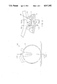
- FIG. 1 is an end view of a horizontal scroll compressor
- FIG. 2 is a sectional view taken along line 2--2 of FIG. 1;
- FIG. 3 is an enlarged view of the bottom portion of the crankcase as viewed looking towards the left in FIG. 2;
- FIG. 4 is a sectional view taken along line 4--4 of FIG. 3;
- FIG. 5 is a sectional view taken along line 5--5 of FIG. 3;
- FIG. 6 is a view of the anti-rotation device.
- the numeral 10 generally designates a low side, horizontal hermetic scroll compressor including a shell 12 made up of end portions 12-1 and 3 which are welded or otherwise suitably joined to middle portion 12-2.
- a low side compressor is one in which most of the shell is filled with gas at suction pressure.
- shell 12 Within shell 12 are fixed scroll member 16, orbiting scroll member 18, anti-rotation device 20 in the form of an Oldham ring or coupling, crankcase 30, crankshaft 32, rotor 34 which is secured to crankshaft 32 and stator 36, as is conventional.
- crankshaft 32 is supported at one end by bearing 40 and is supported at the other end by bearing 42 as well as being connected to boss 18-1 of orbiting scroll 18 via a bushing, sliding block or any other suitable structure 44.
- the structure so far described is generally that of a vertical hermetic scroll placed horizontally.
- the first consequence of the changed orientation is the relocation of the oil sump 50 which causes portions of stator 36, crankcase 30, anti-rotation device 20, orbiting scroll 18 and fixed scroll 16 to be located beneath the level of the oil sump although not necessarily directly exposed to the oil in sump 50.
- a second consequence is the elimination of the need for crankshaft 32 and/or an oil pickup tube (not illustrated) to extend into an oil sump defined by shell member 12-1.
- the shell member 12-3 can be placed closer to the end of crankshaft 32 thereby reducing the length of shell 12 and its cubage.
- the Oldham coupling reciprocates with respect to the fixed scroll 16.
- the orbiting scroll 18 reciprocates with respect to the Oldham coupling 20 but, since the Oldham coupling is also reciprocating at 90 with respect to the direction of reciprocation of the orbiting scroll 18, the net result is an orbiting motion of orbiting scroll 18 with respect to fixed structure in a shell 12 such as fixed scroll 16.
- the motion of either the anti-rotation device 20 can be adopted to drive a positive displacement pump according to the teachings of the present invention.
- anti-rotation device 20 is formed as an Oldham coupling which reciprocates vertically with respect to the crankcase 30 and is modified, as compared to a conventional Oldham coupling, by extending the lowermost key 22 so that it defines a piston.
- Key/piston 22 is reciprocatably received in piston bore 30-1 which is formed in crankcase 30.
- Bore 30-1 is in fluid communication with oil sump 50 via bore 30-2 and fluid diode 24 which is a device having a different flow resistance in opposite directions of flow such that fluid diode 24 defines the suction port.
- bore 30-1 is in fluid communication with bore 30-3 which is connected to radial bore 30-4 containing fluid diode 26 which defines the discharge port.
- radial bore 30-4 intersects with and terminates at axial bore 30-5.
- One end of axial bore 30-5 terminates at annular groove 30-6 which faces orbiting scroll 18.
- the other end of bore 30-5 intersects radial bore 30-7.
- Radial bore 30-7 terminates at radial bore 42-1 which extends through bearing 42.
- An annular groove 32-1 is formed in crankshaft 32 opposite bore 42-1.
- An axial bore 32-3 is formed in crankshaft 32 and extends for its length. Bore 32-3 is connected to groove 32-1 via generally radial bore 32-2 and is connected to bearing 40 via radial bore 32-4.
- Oldham coupling 20 reciprocates up and down due to its coaction with crankcase 30 and orbiting scroll 18.
- Oldham coupling 20 reciprocates key/piston 22 which is received in and coacts with bore 30-1 drawing oil from the sump 50 via fluid diode 24 and bore 30-2 and discharging it via bores 30-3 and 4 and fluid diode 26 into bore 30-5 at an elevated pressure which is sufficient to feed the oil to any place in the shell 12 without requiring a further pressure boost.
- bore 30-5 is fluidly connected to annular groove 30-6 at the interface between orbiting scroll 18 and crankcase 30. The pressure of the oil is sufficient to fill groove 30-6 and thereby provide #lubrication between the orbiting scroll 18 and crankcase 30.
- Oil supplied to bore 30-5 also passes via bores 30-7 and 42-1 into groove 32-1 which fills with oil and provides lubrication between bearing 42 and crankshaft 32.
- a portion of the oil supplied to groove 32-1 is supplied to bore 32-3 via bore 32-2.
- the oil supplied to bore 32-3 is divided. One portion flows into the cavity defined by bore 32-5 of crankcase 32 which contains boss 18-1 of orbiting scroll 18 and bushing or sliding block 44.
- the other portion of the oil is supplied to bearing 40 via bore 32-4. Since the oil is only being pumped several inches, theres is no need for a centrifugal boost.
Landscapes
- Engineering & Computer Science (AREA)
- Mechanical Engineering (AREA)
- General Engineering & Computer Science (AREA)
- Rotary Pumps (AREA)
- Applications Or Details Of Rotary Compressors (AREA)
- Compressor (AREA)
- Compressors, Vaccum Pumps And Other Relevant Systems (AREA)
Abstract
Description
Claims (6)
Priority Applications (10)
| Application Number | Priority Date | Filing Date | Title |
|---|---|---|---|
| US07/315,982 US4917582A (en) | 1989-02-27 | 1989-02-27 | Horizontal scroll compressor with oil pump |
| CA002007108A CA2007108C (en) | 1989-02-27 | 1990-01-04 | Horizontal scroll compressor |
| BR909000475A BR9000475A (en) | 1989-02-27 | 1990-02-02 | HERMETIC HORIZONTAL SPIRAL COMPRESSOR |
| ES90630041T ES2044520T3 (en) | 1989-02-27 | 1990-02-14 | CENTRIFUGAL COMPRESSOR OR HORIZONTAL SNAIL. |
| EP90630041A EP0385915B1 (en) | 1989-02-27 | 1990-02-14 | Horizontal scroll compressor |
| DE90630041T DE69003412T2 (en) | 1989-02-27 | 1990-02-14 | Horizontal scroll compressor. |
| MX019633A MX170098B (en) | 1989-02-27 | 1990-02-23 | LOBE COMPRESSOR, HORIZONTAL |
| AR90316247A AR243010A1 (en) | 1989-02-27 | 1990-02-26 | Horizontal scroll compressor |
| KR1019900002444A KR910015791A (en) | 1989-02-27 | 1990-02-26 | Horizontal moving compressor |
| JP2047094A JPH02267379A (en) | 1989-02-27 | 1990-02-27 | Horizontal type scroll compressor |
Applications Claiming Priority (1)
| Application Number | Priority Date | Filing Date | Title |
|---|---|---|---|
| US07/315,982 US4917582A (en) | 1989-02-27 | 1989-02-27 | Horizontal scroll compressor with oil pump |
Publications (1)
| Publication Number | Publication Date |
|---|---|
| US4917582A true US4917582A (en) | 1990-04-17 |
Family
ID=23226956
Family Applications (1)
| Application Number | Title | Priority Date | Filing Date |
|---|---|---|---|
| US07/315,982 Expired - Lifetime US4917582A (en) | 1989-02-27 | 1989-02-27 | Horizontal scroll compressor with oil pump |
Country Status (10)
| Country | Link |
|---|---|
| US (1) | US4917582A (en) |
| EP (1) | EP0385915B1 (en) |
| JP (1) | JPH02267379A (en) |
| KR (1) | KR910015791A (en) |
| AR (1) | AR243010A1 (en) |
| BR (1) | BR9000475A (en) |
| CA (1) | CA2007108C (en) |
| DE (1) | DE69003412T2 (en) |
| ES (1) | ES2044520T3 (en) |
| MX (1) | MX170098B (en) |
Cited By (8)
| Publication number | Priority date | Publication date | Assignee | Title |
|---|---|---|---|---|
| US5330335A (en) * | 1991-07-31 | 1994-07-19 | Sanden Corporation | Horizontally oriented rotary machine having internal lubication oil pump |
| US5569028A (en) * | 1994-11-30 | 1996-10-29 | Matsushita Electric Industrial Co., Ltd. | Scroll compressor having a compressor housing made up of a cup-like front casing and a cap-like rear casing |
| WO1999064745A1 (en) * | 1998-06-09 | 1999-12-16 | Danfoss A/S | Lubricating oil supplying arrangement for an apparatus having a rotating apparatus shaft |
| US6210137B1 (en) * | 1998-12-28 | 2001-04-03 | Tokico Ltd. | Scroll fluid machine |
| US20060171831A1 (en) * | 2005-01-28 | 2006-08-03 | Elson John P | Scroll machine |
| US7566210B2 (en) | 2005-10-20 | 2009-07-28 | Emerson Climate Technologies, Inc. | Horizontal scroll compressor |
| EP2584199A3 (en) * | 2011-10-17 | 2014-02-26 | Kabushiki Kaisha Toyota Jidoshokki | Motor-driven compressor |
| US8747088B2 (en) | 2007-11-27 | 2014-06-10 | Emerson Climate Technologies, Inc. | Open drive scroll compressor with lubrication system |
Families Citing this family (5)
| Publication number | Priority date | Publication date | Assignee | Title |
|---|---|---|---|---|
| US6017205A (en) * | 1996-08-02 | 2000-01-25 | Copeland Corporation | Scroll compressor |
| AU5783898A (en) | 1997-02-03 | 1998-08-25 | Dec International Nz Limited | Active delivery device and related procedures |
| JP2004301092A (en) * | 2003-03-31 | 2004-10-28 | Toyota Industries Corp | Scroll compressor |
| DE102013200805A1 (en) * | 2013-01-18 | 2014-07-24 | Mahle International Gmbh | Scroll compressor installed in air conditioning apparatus for delivering fluid, provides orbiting motion of inner ring with respect to outer ring during activation state so that slider mechanism compress compressor for delivering fluid |
| DE102013218430A1 (en) * | 2013-09-13 | 2015-03-19 | Mahle International Gmbh | Scroll compressor |
Citations (13)
| Publication number | Priority date | Publication date | Assignee | Title |
|---|---|---|---|---|
| US4129405A (en) * | 1977-06-17 | 1978-12-12 | Arthur D. Little, Inc. | Scroll-type liquid pump with transfer passages in end plate |
| US4385875A (en) * | 1979-07-28 | 1983-05-31 | Tokyo Shibaura Denki Kabushiki Kaisha | Rotary compressor with fluid diode check value for lubricating pump |
| JPS5960092A (en) * | 1982-09-30 | 1984-04-05 | Toshiba Corp | Scroll compressor |
| JPS59120796A (en) * | 1982-12-27 | 1984-07-12 | Mitsubishi Electric Corp | scroll compressor |
| US4544338A (en) * | 1983-05-27 | 1985-10-01 | Hitachi, Ltd. | Oil feeder means for use in a horizontal type rotary compressor |
| US4561829A (en) * | 1983-03-10 | 1985-12-31 | Hitachi, Ltd. | Rotary compressor with tapered valve ports for lubricating pump |
| US4568253A (en) * | 1983-11-29 | 1986-02-04 | Tecumseh Products Company | Horizontal shaft oil pump |
| US4626180A (en) * | 1983-07-29 | 1986-12-02 | Hitachi, Ltd. | Rotary compressor with spiral oil grooves for crankshaft |
| US4637786A (en) * | 1984-06-20 | 1987-01-20 | Daikin Industries, Ltd. | Scroll type fluid apparatus with lubrication of rotation preventing mechanism and thrust bearing |
| JPS62113880A (en) * | 1985-11-13 | 1987-05-25 | Hitachi Ltd | scroll fluid machine |
| US4712986A (en) * | 1985-08-13 | 1987-12-15 | Danfoss A/S | Oil feeding apparatus for a rotary compressor |
| US4781542A (en) * | 1986-06-02 | 1988-11-01 | Kabushiki Kaisha Toshiba | Hermetically-sealed compressor with motor |
| US4818198A (en) * | 1986-11-26 | 1989-04-04 | Hitachi, Ltd. | Scroll fluid machine with oil feed passages |
Family Cites Families (2)
| Publication number | Priority date | Publication date | Assignee | Title |
|---|---|---|---|---|
| US4082484A (en) * | 1977-01-24 | 1978-04-04 | Arthur D. Little, Inc. | Scroll-type apparatus with fixed throw crank drive mechanism |
| JPS59183095A (en) * | 1983-03-31 | 1984-10-18 | Toshiba Corp | Scroll type compressing device |
-
1989
- 1989-02-27 US US07/315,982 patent/US4917582A/en not_active Expired - Lifetime
-
1990
- 1990-01-04 CA CA002007108A patent/CA2007108C/en not_active Expired - Fee Related
- 1990-02-02 BR BR909000475A patent/BR9000475A/en not_active IP Right Cessation
- 1990-02-14 EP EP90630041A patent/EP0385915B1/en not_active Expired - Lifetime
- 1990-02-14 ES ES90630041T patent/ES2044520T3/en not_active Expired - Lifetime
- 1990-02-14 DE DE90630041T patent/DE69003412T2/en not_active Expired - Fee Related
- 1990-02-23 MX MX019633A patent/MX170098B/en unknown
- 1990-02-26 KR KR1019900002444A patent/KR910015791A/en not_active Ceased
- 1990-02-26 AR AR90316247A patent/AR243010A1/en active
- 1990-02-27 JP JP2047094A patent/JPH02267379A/en active Pending
Patent Citations (13)
| Publication number | Priority date | Publication date | Assignee | Title |
|---|---|---|---|---|
| US4129405A (en) * | 1977-06-17 | 1978-12-12 | Arthur D. Little, Inc. | Scroll-type liquid pump with transfer passages in end plate |
| US4385875A (en) * | 1979-07-28 | 1983-05-31 | Tokyo Shibaura Denki Kabushiki Kaisha | Rotary compressor with fluid diode check value for lubricating pump |
| JPS5960092A (en) * | 1982-09-30 | 1984-04-05 | Toshiba Corp | Scroll compressor |
| JPS59120796A (en) * | 1982-12-27 | 1984-07-12 | Mitsubishi Electric Corp | scroll compressor |
| US4561829A (en) * | 1983-03-10 | 1985-12-31 | Hitachi, Ltd. | Rotary compressor with tapered valve ports for lubricating pump |
| US4544338A (en) * | 1983-05-27 | 1985-10-01 | Hitachi, Ltd. | Oil feeder means for use in a horizontal type rotary compressor |
| US4626180A (en) * | 1983-07-29 | 1986-12-02 | Hitachi, Ltd. | Rotary compressor with spiral oil grooves for crankshaft |
| US4568253A (en) * | 1983-11-29 | 1986-02-04 | Tecumseh Products Company | Horizontal shaft oil pump |
| US4637786A (en) * | 1984-06-20 | 1987-01-20 | Daikin Industries, Ltd. | Scroll type fluid apparatus with lubrication of rotation preventing mechanism and thrust bearing |
| US4712986A (en) * | 1985-08-13 | 1987-12-15 | Danfoss A/S | Oil feeding apparatus for a rotary compressor |
| JPS62113880A (en) * | 1985-11-13 | 1987-05-25 | Hitachi Ltd | scroll fluid machine |
| US4781542A (en) * | 1986-06-02 | 1988-11-01 | Kabushiki Kaisha Toshiba | Hermetically-sealed compressor with motor |
| US4818198A (en) * | 1986-11-26 | 1989-04-04 | Hitachi, Ltd. | Scroll fluid machine with oil feed passages |
Cited By (11)
| Publication number | Priority date | Publication date | Assignee | Title |
|---|---|---|---|---|
| US5330335A (en) * | 1991-07-31 | 1994-07-19 | Sanden Corporation | Horizontally oriented rotary machine having internal lubication oil pump |
| US5569028A (en) * | 1994-11-30 | 1996-10-29 | Matsushita Electric Industrial Co., Ltd. | Scroll compressor having a compressor housing made up of a cup-like front casing and a cap-like rear casing |
| WO1999064745A1 (en) * | 1998-06-09 | 1999-12-16 | Danfoss A/S | Lubricating oil supplying arrangement for an apparatus having a rotating apparatus shaft |
| US6210137B1 (en) * | 1998-12-28 | 2001-04-03 | Tokico Ltd. | Scroll fluid machine |
| DE19962798C2 (en) * | 1998-12-28 | 2003-10-30 | Tokico Ltd | Spiral compressor or spiral pump |
| US20060171831A1 (en) * | 2005-01-28 | 2006-08-03 | Elson John P | Scroll machine |
| US7186099B2 (en) | 2005-01-28 | 2007-03-06 | Emerson Climate Technologies, Inc. | Inclined scroll machine having a special oil sump |
| US7566210B2 (en) | 2005-10-20 | 2009-07-28 | Emerson Climate Technologies, Inc. | Horizontal scroll compressor |
| US8747088B2 (en) | 2007-11-27 | 2014-06-10 | Emerson Climate Technologies, Inc. | Open drive scroll compressor with lubrication system |
| EP2584199A3 (en) * | 2011-10-17 | 2014-02-26 | Kabushiki Kaisha Toyota Jidoshokki | Motor-driven compressor |
| US9644628B2 (en) | 2011-10-17 | 2017-05-09 | Kabushiki Kaisha Toyota Jidoshokki | Motor-driven compressor having oil passage that facilitates bearing lubrication |
Also Published As
| Publication number | Publication date |
|---|---|
| DE69003412T2 (en) | 1994-03-10 |
| KR910015791A (en) | 1991-09-30 |
| BR9000475A (en) | 1991-01-15 |
| DE69003412D1 (en) | 1993-10-28 |
| CA2007108A1 (en) | 1990-08-27 |
| EP0385915A2 (en) | 1990-09-05 |
| JPH02267379A (en) | 1990-11-01 |
| AR243010A1 (en) | 1993-06-30 |
| MX170098B (en) | 1993-08-06 |
| EP0385915B1 (en) | 1993-09-22 |
| ES2044520T3 (en) | 1994-01-01 |
| EP0385915A3 (en) | 1991-01-02 |
| CA2007108C (en) | 1996-02-13 |
Similar Documents
| Publication | Publication Date | Title |
|---|---|---|
| KR100294429B1 (en) | Scroll machine | |
| US4946361A (en) | Horizontal scroll compressor with oil pump | |
| JP3335656B2 (en) | Horizontal compressor | |
| US4637786A (en) | Scroll type fluid apparatus with lubrication of rotation preventing mechanism and thrust bearing | |
| US4917582A (en) | Horizontal scroll compressor with oil pump | |
| KR890003271B1 (en) | Scroll compressor | |
| US5772411A (en) | Gas flow and lubrication of a scroll compressor | |
| US5660539A (en) | Scroll compressor | |
| US5012896A (en) | Lubricating system for rotary horizontal crankshaft hermetic compressor | |
| US4385875A (en) | Rotary compressor with fluid diode check value for lubricating pump | |
| US4889471A (en) | Mechanism for prevention of burning of bearing portions in a hermetic type scroll compressor | |
| US5221191A (en) | Horizontal rotary compressor | |
| US5088897A (en) | Swash plate type compressor with internal refrigerant and lubricant separating system | |
| JP3459451B2 (en) | Lubrication device for horizontal hermetic rotary compressor | |
| US5322420A (en) | Horizontal rotary compressor | |
| US6637550B2 (en) | Displacement type fluid machine | |
| US6338617B1 (en) | Helical-blade fluid machine | |
| JP2000310191A (en) | Rolling piston type rotary compressor | |
| JP2009127440A (en) | Scroll compressor | |
| JPH09287579A (en) | Hermetic scroll compressor | |
| JP2708537B2 (en) | Oil supply device for scroll fluid machine | |
| KR100297177B1 (en) | Fluid apparatus | |
| JP3601067B2 (en) | Hermetic compressor | |
| JPH0754788A (en) | Hermetic compressor | |
| JPH08284827A (en) | Hermetic compressor |
Legal Events
| Date | Code | Title | Description |
|---|---|---|---|
| AS | Assignment |
Owner name: CARRIER CORPORATION, CARRIER PARKWAY, A CORP. OF D Free format text: ASSIGNMENT OF ASSIGNORS INTEREST.;ASSIGNORS:FRASER, HOWARD H. JR.;KASSOUF, THOMAS L.;REEL/FRAME:005031/0814 Effective date: 19890227 |
|
| STCF | Information on status: patent grant |
Free format text: PATENTED CASE |
|
| FEPP | Fee payment procedure |
Free format text: PAYOR NUMBER ASSIGNED (ORIGINAL EVENT CODE: ASPN); ENTITY STATUS OF PATENT OWNER: LARGE ENTITY |
|
| FPAY | Fee payment |
Year of fee payment: 4 |
|
| FEPP | Fee payment procedure |
Free format text: PAYER NUMBER DE-ASSIGNED (ORIGINAL EVENT CODE: RMPN); ENTITY STATUS OF PATENT OWNER: LARGE ENTITY |
|
| FPAY | Fee payment |
Year of fee payment: 8 |
|
| FPAY | Fee payment |
Year of fee payment: 12 |