US4912685A - Side looking sonar apparatus - Google Patents
Side looking sonar apparatus Download PDFInfo
- Publication number
- US4912685A US4912685A US07/278,069 US27806988A US4912685A US 4912685 A US4912685 A US 4912685A US 27806988 A US27806988 A US 27806988A US 4912685 A US4912685 A US 4912685A
- Authority
- US
- United States
- Prior art keywords
- target area
- transducer
- plane
- arc
- transmitter transducer
- Prior art date
- Legal status (The legal status is an assumption and is not a legal conclusion. Google has not performed a legal analysis and makes no representation as to the accuracy of the status listed.)
- Expired - Fee Related
Links
Images


Classifications
-
- G—PHYSICS
- G01—MEASURING; TESTING
- G01S—RADIO DIRECTION-FINDING; RADIO NAVIGATION; DETERMINING DISTANCE OR VELOCITY BY USE OF RADIO WAVES; LOCATING OR PRESENCE-DETECTING BY USE OF THE REFLECTION OR RERADIATION OF RADIO WAVES; ANALOGOUS ARRANGEMENTS USING OTHER WAVES
- G01S15/00—Systems using the reflection or reradiation of acoustic waves, e.g. sonar systems
- G01S15/88—Sonar systems specially adapted for specific applications
- G01S15/89—Sonar systems specially adapted for specific applications for mapping or imaging
- G01S15/8902—Side-looking sonar
-
- G—PHYSICS
- G10—MUSICAL INSTRUMENTS; ACOUSTICS
- G10K—SOUND-PRODUCING DEVICES; METHODS OR DEVICES FOR PROTECTING AGAINST, OR FOR DAMPING, NOISE OR OTHER ACOUSTIC WAVES IN GENERAL; ACOUSTICS NOT OTHERWISE PROVIDED FOR
- G10K11/00—Methods or devices for transmitting, conducting or directing sound in general; Methods or devices for protecting against, or for damping, noise or other acoustic waves in general
- G10K11/18—Methods or devices for transmitting, conducting or directing sound
- G10K11/26—Sound-focusing or directing, e.g. scanning
- G10K11/34—Sound-focusing or directing, e.g. scanning using electrical steering of transducer arrays, e.g. beam steering
- G10K11/341—Circuits therefor
- G10K11/346—Circuits therefor using phase variation
Definitions
- the invention in general relates to side looking sonar equipment and particularly to a transmitting transducer therefore.
- the sonar apparatus is mounted on a carrier vehicle which travels along a course line at a certain altitude above the target area to be examined.
- a transmitting transducer propagates acoustic energy to ether side of the course line and impinges upon the target area in a relatively narrow strip, such impingement process being termed insonification.
- a receiver transducer receives the acoustic energy reflected from the insonfied strip and during the course of travel of the carrier vehicle, the return signals are portrayed on a line-by-line basis that is a pattern of highlights and shadows analogous to an optically viewed panorama illuminated by side lighting, with objects outlined in such a way as to permit their identification.
- the carrier speed and therefore the search or mapping rate may be significantly increased by increasing the area detected and portrayed for each acoustic transmission. This is accomplished with the use of signal processing apparatus which forms a plurality of receiver beams each of which looks at a relatively narrow strip of the insonified region.
- the insonified region for the eight beam system is approximately the width of the eight beams at some minimum range of interest and slightly increases in width out to some maximum range of interest so as to define a trapezoidal pattern. This width difference is desired in order to accommodate for small variations in carrier speed as well as any oscillatory motion of the carrier vehicle about a vertical axis (yawing).
- a typical high resolution system may form three receiver beams and in such instance the transmitting transducer utilized in the eight beam system cannot be used for the three beam system because the insonification pattern would be too wide. Smaller transmitter transducers often used for the high resolution system cannot accommodate the power input required for the desired insonification and often experience cracking and total failure.
- the side looking sonar apparatus of the present invention may be used for high resolution work and includes a transmitter transducer which can accommodate a high power input signal to properly insonify the target area.
- the side looking sonar apparatus described herein includes an elongated transmitter transducer which lies along an arc of a circle having a radius R.
- the arc lies in a plane which is at a certain angle ⁇ with respect to vertical during operation, where ⁇ is no more than 6° and preferably in the order of one or two degrees.
- the transmitter transducer is operated at an altitude H above the target area.
- H and R must be of different values.
- Means are provided for energizing the transmitter transducer to periodically project acoustic energy toward the target area.
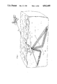
- FIG. 1 illustrates a towed carrier multibeam side looking sonar system
- FIGS. 2A and 2B illustrate the receiver beams of the side looking sonar system superimposed upon an insonified region of the target area
- FIG. 3 is an XYZ coordinate system serving to illustrate the orientation of the transmitter transducer for the apparatus of FIG. 1;
- FIG. 4 illustrates the receiver beams formed for a high resolution, fewer beam, side looking sonar system
- FIG. 5 illustrates one type of prior art transmitter transducer
- FIG. 6 is an XYZ coordinate system illustrating the principles of a focused side looking sonar arc transducer of the prior art
- FIG. 7 illustrates, in an XYZ coordinate system, the orientation of an arc transducer in accordance with one embodiment of the present invention
- FIG. 7A is a view of 7 looking in along the Y axis
- FIG. 7B is a view of FIG. 7 looking in along the X axis
- FIGS. 8A and 8B are respective X axis and Y axis views of an XYZ coordinate system illustrating another embodiment of the present invention.
- FIGS. 9A and 9B are respective X axis and Y axis views of an XYZ coordinate system illustrating another embodiment of the present invention.
- FIG. 10 is a simplified block diagram of a said looking sonar transducer system utilized in conjunction with the embodiment of the invention illustrated in FIG. 7;
- FIG. 11 illustrates a modification of the apparatus for practicing the embodiments of FIGS. 8B and 9B.
- FIG. 1 there is illustrated a multibeam side looking sonar system carried by an underwater vehicle 10 which is towed along a course line over a target area 12, such as the sea bottom, by means of a tow vehicle.
- a target area 12 such as the sea bottom
- tow vehicle is illustrated as a helicopter 14 although surface and subsurface vessels may also be utilized.
- the apparatus is towed at a certain altitude above the target area 12 and the projection of the line of travel, on the bottom is labeled C.
- the system will generally employ both starboard beams 16 and port beams 16'.
- the receiver beam signals indicative of the target area are transmitted via a cable 18 to display equipment on the towing vehicle 14.
- FIG. 2A illustrates a plan view of the target area and shows a rectangular insonified zone 20 which extends from some minimum range R min out to some maximum range R max .
- superimposed upon the insonified zone 20 are relatively narrow adjacent receiver beams B1 to B8, each for obtaining acoustic information relative to a respective narrow strip on the target area for subsequent display.
- the carrier vehicle may be subject to a limited oscillatory rotational movement or variation in speed.
- the insonified area is made wider at maximum range than it is at minimum range, such insonified area being designated by the numeral 21 in FIG. 2B and having superimposed thereon the receiver beams B1 to B8.
- FIG. 3 illustrates one method by which the trapezoidal insonified zone of FIG. 2B may be produced.
- Insonified zone 24 lies along the X axis in the XY place representing the target area 12.
- the transmitter transducer lies along an arc 26 on the Z axis at an altitude H above the XY plane.
- Arc 26 is an arc of a circle which lies in the plane P1 shown in FIG. 3 to be parallel to the XY plane.
- the transmitter transducer which lies along arc 26 is made up of a plurality of adjacent elongated active transducer elements such as barium titanite or lead zirconate titanite with each element being given a certain depression angle.
- FIG. 3 represents an orientation which is currently in use, and a variation in which the plane P1 itself is given a certain depression angle with respect to horizontal is illustrated in application Ser. No. 932,584, now abandoned.
- the insonification pattern illustrated in FIG. 2B and generated by the apparatus of FIG. 3 is sufficient for a good resolution 8 beam system.
- FIG. 4 illustrates the three beams N1, N2 and N3 of such system.
- FIG. 4 additionally illustrates a straight line receiver transducer 30, such transducer commonly being made up of a plurality of adjacent elongated active elements 31 each being operable to provide a respective output signal upon the receipt of reflected acoustic energy from the insonified area.
- the output signals generated by the active elements are provided to signal processing apparatus (not shown) which forms the multiple beams and an example of which is illustrated in U.S. Pat. No. 3,950,723 hereby incorporated by reference.
- the signal processing for forming beams N1 to N3 involves the phase shifting of the individual output signals of th transducer elements 31.
- the signal processing in addition, to generating the desired receiver beams, also generates grating side lobes for each beam, these side lobes being respectively designated as S1 to S3.
- the desired insonification pattern on the target area is designated by the numeral 34 and it is seen that the pattern is of such configuration as to generally exclude as much as possible, the side lobes, from minimum range to maximum range, so that any target returns will be received on beams N1 to N3. If the apparatus of FIG.
- the pattern 34 would be much wider so as to encompass the side lobes thereby subjecting the apparatus to potentionally false target direction information.
- One potential solution for obtaining the narrower insonification zone is to decrease the length of the transmitter transducer. In order to get the desired acoustic intensity and maximum range, a certain amount of power must be supplied to the transmitting transducer. If the length of the transducer is decreased in order to reduce the size of the insonified zone, the tota power applied to the decreased length transducer may be sufficient to crack and destroy individual transducer elements.
- FIG. 5 is a front view of the transducer and it is seen to be composed of a plurality of segments, with the end segments 40, 41 each being comprised of 5 stacked active transducer elements, the next sections 42, 43 being comprised of 4 stacked elements, the next section 44, 45 being comprised of two stacked elements and a center section 46 being comprised o a single element.
- the transducer is shaded, that is different powers are supplied to different sections, as illustrated. Although this transducer is an improvement over the shorter arc transducer, under certain operating conditions the insonified area was not as uniform as desired and the center element 46 was still prone to cracking.
- FIG. 6 is presented to illustrate the principles of a focused arc transducer.
- An XYZ coordinate system is illustrated with the XY plane containing the target area to be insonified.
- Arc 50 extending between points a and b represents a curved transducer which lies in vertical plane Pl at a distance or altitude H from origin O.
- the curved transducer lies on a section of a circle having as its center the point O with a radius equal to R, and accordingly each point on the arc 50 is at the same distance R from point O.
- Line F coincident with the X axis, is known as the line of focus and is perpendicular to the plane of the circle at point O and at any point on line F is equidistant to all points on the arc 50.
- the transmitter transducer may be comprised of a plurality of active transducer elements, the active faces of which lie along the arc 50 and when supplied with electrical energy to transmit, will insonify in theory, the line of focus out to some maximum range, but in actuality will insonify a small trapezoidal area 52 which may be wide enough for a single beam system but not for a multi-beam system such as illustrated in FIG. 4.
- FIG. 7, illustrating one embodiment of the present invention is a modification of the arrangement of FIG. 6 in order to provide for a larger insonified area of sufficient size to accommodate the three beam system of FIG. 4 but being of a limited size so as to exclude false target information which may be picked up by the generated side lobes.
- FIG. 7 illustrates the same arc transducer 50 as in FIG. 6, however, with a modified orientation. More particularly, considering the XY plane as the target area 12, the arc 50 is decreased in altitude such that H ⁇ R and the origin O and line of focus F fall below the XY plane. In addition, the plane P1 containing arc 50 is tilted forward slightly by an angle + ⁇ where ⁇ is in the order of one degree but no more than six degrees. With this orientation, there is provided a trapezoidal insonification zone 54 which meets the desired design requirements.
- the radius of curvature R of arc 50 can be determined from the following equation. ##EQU1## where N is the number of receiver beams, r is the beam resolution and L is the transducer length.
- the angle ⁇ by which the arc 50 is tilted toward the target area may be determined as follows: ##EQU2## where ⁇ is in radians, is the number of beam widths at minimum range and x is the additional beam widths at maximum range.
- FIG. 7A is a view of FIG. 7 looking in at the Y axis and illustrates the plane P1 at the angle ⁇ which is the same angle by which the line of focus F is depressed from horizontal.
- FIG. 7B is a view of FIG. 7 looking in along the X axis and further illustrates the relationship between altitude H and radius of curvature R, with the origin O being below the XY plane.
- FIGS. 8A, 8B and 9A, 9B illustrate other embodiments of the present invention to accommodate for full and half range modes of operation.
- FIG. 8A is a view of an XYZ coordinate system looking in along the X axis toward the YZ plane
- FIG. 8B is a view looking in along the Y axis.
- Arc 60 is in the P1 plane and has a radius of curvature R such that the focal line F falls above the XY plane.
- Plane P1 is tilted not toward, but away from the target area (the XY plane) by an angle - ⁇ where ⁇ is preferably in the order of one degree but no more than six degrees.
- ⁇ is preferably in the order of one degree but no more than six degrees.
- the width of the insonified area at the YZ plane would be W and this width would progressively increase out to maximum range to define a trapezoidal insonified area.
- FIGS. 9A and 9B may be utilized.
- plane P1 containing the arc 60 is tilted toward the target area by the angle + ⁇ and the line of focus F falls below the XY plane.
- the initial width of the insonified area for the dimensions illustrated will be the desired width W/2.
- FIG. 10 illustrates the apparatus for performing the embodiment of FIG. 7.
- numeral 30 represents the receiving transducer and numeral 64 represents a transmitting transducer which lies along the arc of a circle as previously described with respect to FIG. 7.
- Both transducers may be contained in a single housing 66 and signal processing apparatus 88 may be operable to provide an initiating signal to transmitter 70 to cause a energization of the transmitting transducer 64 and the projection of acoustic energy to insonify the desired area. Thereafter, acoustic returns impinge upon receiving transducer 30, and receiver apparatus 72 in conjunction with signal processing apparatus 88 form multiple receiver beams to examine extremely narrow areas of the insonified zone with the results of such analysis being provided to display 74. The transmissions take place periodically during travel over the target area so that a picture of the entire area of interest may be displayed and recorded.
- FIG. 11 would employ the same signal processing and display apparatus as in FIG. 10 however, the transducer housing may be separated such that receiver transducer 30 is contained in a housing 82 and transmitting transducer 80 is contained in a housing 83 which may be rotatable about a horizontal axis by means of adjustment mechanism 86 so as to vary the angle ⁇ so as to be able to practice the full range and half range modes of operation as described with respect to 8A, 8B and 9A, 9B.
Landscapes
- Engineering & Computer Science (AREA)
- Radar, Positioning & Navigation (AREA)
- Remote Sensing (AREA)
- Physics & Mathematics (AREA)
- Acoustics & Sound (AREA)
- Computer Networks & Wireless Communication (AREA)
- General Physics & Mathematics (AREA)
- Multimedia (AREA)
- Measurement Of Velocity Or Position Using Acoustic Or Ultrasonic Waves (AREA)
Abstract
Description
Claims (7)
Priority Applications (2)
| Application Number | Priority Date | Filing Date | Title |
|---|---|---|---|
| US07/278,069 US4912685A (en) | 1988-11-30 | 1988-11-30 | Side looking sonar apparatus |
| FR8915184A FR2639718B1 (en) | 1988-11-30 | 1989-11-20 | ULTRASONIC RADAR WITH SIDE VIEW, PARTICULARLY ON BOARD IN AN UNDERWATER VEHICLE MOVING ABOVE A VIEW OF SURFACE |
Applications Claiming Priority (1)
| Application Number | Priority Date | Filing Date | Title |
|---|---|---|---|
| US07/278,069 US4912685A (en) | 1988-11-30 | 1988-11-30 | Side looking sonar apparatus |
Publications (1)
| Publication Number | Publication Date |
|---|---|
| US4912685A true US4912685A (en) | 1990-03-27 |
Family
ID=23063562
Family Applications (1)
| Application Number | Title | Priority Date | Filing Date |
|---|---|---|---|
| US07/278,069 Expired - Fee Related US4912685A (en) | 1988-11-30 | 1988-11-30 | Side looking sonar apparatus |
Country Status (2)
| Country | Link |
|---|---|
| US (1) | US4912685A (en) |
| FR (1) | FR2639718B1 (en) |
Cited By (16)
| Publication number | Priority date | Publication date | Assignee | Title |
|---|---|---|---|---|
| US5200931A (en) * | 1991-06-18 | 1993-04-06 | Alliant Techsystems Inc. | Volumetric and terrain imaging sonar |
| US5241314A (en) * | 1991-08-16 | 1993-08-31 | Kaman Aerospace Corporation | Image lidar transmitter downlink for command guidance of underwater vehicle |
| US5248978A (en) * | 1991-08-16 | 1993-09-28 | Kaman Aerospace Corporation | Underwater guide vehicle for removal of submerged and floating navigational hazards |
| US5442358A (en) * | 1991-08-16 | 1995-08-15 | Kaman Aerospace Corporation | Imaging lidar transmitter downlink for command guidance of underwater vehicle |
| US5451957A (en) * | 1993-07-14 | 1995-09-19 | Daimler-Benz Aerospace Ag | Radar device for obstacle warning |
| US5614907A (en) * | 1996-03-14 | 1997-03-25 | Daimler-Benz Aerospace Ag | All weather visual system for helicopters |
| US20060023570A1 (en) * | 2004-08-02 | 2006-02-02 | Johnson Outdoors Inc. | Sonar imaging system for mounting to watercraft |
| US7420504B1 (en) * | 2005-04-22 | 2008-09-02 | Northrop Grumman Corporation | Method of operating a multibeam radar |
| US20110013484A1 (en) * | 2009-07-14 | 2011-01-20 | Navico, Inc. | Linear and circular downscan imaging sonar |
| US8305840B2 (en) | 2009-07-14 | 2012-11-06 | Navico, Inc. | Downscan imaging sonar |
| US9142206B2 (en) | 2011-07-14 | 2015-09-22 | Navico Holding As | System for interchangeable mounting options for a sonar transducer |
| US9182486B2 (en) | 2011-12-07 | 2015-11-10 | Navico Holding As | Sonar rendering systems and associated methods |
| US9244168B2 (en) | 2012-07-06 | 2016-01-26 | Navico Holding As | Sonar system using frequency bursts |
| US9268020B2 (en) | 2012-02-10 | 2016-02-23 | Navico Holding As | Sonar assembly for reduced interference |
| US10151829B2 (en) | 2016-02-23 | 2018-12-11 | Navico Holding As | Systems and associated methods for producing sonar image overlay |
| US11367425B2 (en) | 2017-09-21 | 2022-06-21 | Navico Holding As | Sonar transducer with multiple mounting options |
Citations (7)
| Publication number | Priority date | Publication date | Assignee | Title |
|---|---|---|---|---|
| US3585579A (en) * | 1969-07-09 | 1971-06-15 | Westinghouse Electric Corp | Side looking sonar transducer |
| US3742436A (en) * | 1971-03-24 | 1973-06-26 | Westinghouse Electric Corp | Side looking sonar apparatus |
| US3950723A (en) * | 1974-02-21 | 1976-04-13 | Westinghouse Electric Corporation | Sonar apparatus |
| US3967234A (en) * | 1974-03-06 | 1976-06-29 | Westinghouse Electric Corporation | Depth-of-field arc-transducer and sonar system |
| US4024490A (en) * | 1976-02-27 | 1977-05-17 | Westinghouse Electric Corporation | Multibeam sidelooking sonar display system |
| US4199746A (en) * | 1978-04-18 | 1980-04-22 | Westinghouse Electric Corp. | Side looking sonar apparatus |
| US4802148A (en) * | 1982-11-08 | 1989-01-31 | Westinghouse Electric Corp. | Side-looking sonar apparatus |
Family Cites Families (1)
| Publication number | Priority date | Publication date | Assignee | Title |
|---|---|---|---|---|
| US4187556A (en) * | 1960-04-05 | 1980-02-05 | The United States Of America As Represented By The Secretary Of The Navy | Electro-acoustic transducer with line focus |
-
1988
- 1988-11-30 US US07/278,069 patent/US4912685A/en not_active Expired - Fee Related
-
1989
- 1989-11-20 FR FR8915184A patent/FR2639718B1/en not_active Expired - Fee Related
Patent Citations (7)
| Publication number | Priority date | Publication date | Assignee | Title |
|---|---|---|---|---|
| US3585579A (en) * | 1969-07-09 | 1971-06-15 | Westinghouse Electric Corp | Side looking sonar transducer |
| US3742436A (en) * | 1971-03-24 | 1973-06-26 | Westinghouse Electric Corp | Side looking sonar apparatus |
| US3950723A (en) * | 1974-02-21 | 1976-04-13 | Westinghouse Electric Corporation | Sonar apparatus |
| US3967234A (en) * | 1974-03-06 | 1976-06-29 | Westinghouse Electric Corporation | Depth-of-field arc-transducer and sonar system |
| US4024490A (en) * | 1976-02-27 | 1977-05-17 | Westinghouse Electric Corporation | Multibeam sidelooking sonar display system |
| US4199746A (en) * | 1978-04-18 | 1980-04-22 | Westinghouse Electric Corp. | Side looking sonar apparatus |
| US4802148A (en) * | 1982-11-08 | 1989-01-31 | Westinghouse Electric Corp. | Side-looking sonar apparatus |
Cited By (29)
| Publication number | Priority date | Publication date | Assignee | Title |
|---|---|---|---|---|
| US5200931A (en) * | 1991-06-18 | 1993-04-06 | Alliant Techsystems Inc. | Volumetric and terrain imaging sonar |
| US5241314A (en) * | 1991-08-16 | 1993-08-31 | Kaman Aerospace Corporation | Image lidar transmitter downlink for command guidance of underwater vehicle |
| US5248978A (en) * | 1991-08-16 | 1993-09-28 | Kaman Aerospace Corporation | Underwater guide vehicle for removal of submerged and floating navigational hazards |
| US5442358A (en) * | 1991-08-16 | 1995-08-15 | Kaman Aerospace Corporation | Imaging lidar transmitter downlink for command guidance of underwater vehicle |
| US5451957A (en) * | 1993-07-14 | 1995-09-19 | Daimler-Benz Aerospace Ag | Radar device for obstacle warning |
| US5614907A (en) * | 1996-03-14 | 1997-03-25 | Daimler-Benz Aerospace Ag | All weather visual system for helicopters |
| US20060023570A1 (en) * | 2004-08-02 | 2006-02-02 | Johnson Outdoors Inc. | Sonar imaging system for mounting to watercraft |
| US20090122647A1 (en) * | 2004-08-02 | 2009-05-14 | Johnson Outdoors Inc. | Side scan sonar imaging system with boat position on display |
| US7652952B2 (en) | 2004-08-02 | 2010-01-26 | Johnson Outdoors Inc. | Sonar imaging system for mounting to watercraft |
| US7710825B2 (en) | 2004-08-02 | 2010-05-04 | Johnson Outdoors Inc. | Side scan sonar imaging system with boat position on display |
| US7729203B2 (en) | 2004-08-02 | 2010-06-01 | Johnson Outdoors Inc. | Side scan sonar imaging system with associated GPS data |
| US7755974B2 (en) | 2004-08-02 | 2010-07-13 | Johnson Outdoors Inc. | Side scan sonar imaging system with enhancement |
| US7420504B1 (en) * | 2005-04-22 | 2008-09-02 | Northrop Grumman Corporation | Method of operating a multibeam radar |
| US8300499B2 (en) | 2009-07-14 | 2012-10-30 | Navico, Inc. | Linear and circular downscan imaging sonar |
| US9223022B2 (en) | 2009-07-14 | 2015-12-29 | Navico Holding As | Linear and circular downscan imaging sonar |
| US8305840B2 (en) | 2009-07-14 | 2012-11-06 | Navico, Inc. | Downscan imaging sonar |
| US8514658B2 (en) | 2009-07-14 | 2013-08-20 | Navico Holding As | Downscan imaging sonar for reduced interference |
| US8605550B2 (en) | 2009-07-14 | 2013-12-10 | Navico Holding As | Downscan imaging sonar |
| US10024961B2 (en) | 2009-07-14 | 2018-07-17 | Navico Holding As | Sonar imaging techniques for objects in an underwater environment |
| US9541643B2 (en) | 2009-07-14 | 2017-01-10 | Navico Holding As | Downscan imaging sonar |
| US20110013484A1 (en) * | 2009-07-14 | 2011-01-20 | Navico, Inc. | Linear and circular downscan imaging sonar |
| US9142206B2 (en) | 2011-07-14 | 2015-09-22 | Navico Holding As | System for interchangeable mounting options for a sonar transducer |
| US9182486B2 (en) | 2011-12-07 | 2015-11-10 | Navico Holding As | Sonar rendering systems and associated methods |
| US10247823B2 (en) | 2011-12-07 | 2019-04-02 | Navico Holding As | Sonar rendering systems and associated methods |
| US9268020B2 (en) | 2012-02-10 | 2016-02-23 | Navico Holding As | Sonar assembly for reduced interference |
| US9244168B2 (en) | 2012-07-06 | 2016-01-26 | Navico Holding As | Sonar system using frequency bursts |
| US9354312B2 (en) | 2012-07-06 | 2016-05-31 | Navico Holding As | Sonar system using frequency bursts |
| US10151829B2 (en) | 2016-02-23 | 2018-12-11 | Navico Holding As | Systems and associated methods for producing sonar image overlay |
| US11367425B2 (en) | 2017-09-21 | 2022-06-21 | Navico Holding As | Sonar transducer with multiple mounting options |
Also Published As
| Publication number | Publication date |
|---|---|
| FR2639718B1 (en) | 1993-04-09 |
| FR2639718A1 (en) | 1990-06-01 |
Similar Documents
| Publication | Publication Date | Title |
|---|---|---|
| US4912685A (en) | Side looking sonar apparatus | |
| US3950723A (en) | Sonar apparatus | |
| US4180792A (en) | Transmit-receive transducer array and ultrasonic imaging system | |
| US4970700A (en) | Sonar apparatus | |
| US3585579A (en) | Side looking sonar transducer | |
| US4199746A (en) | Side looking sonar apparatus | |
| US3088113A (en) | Correlation system for radar and the like | |
| US4802148A (en) | Side-looking sonar apparatus | |
| US3585578A (en) | Side looking sonar apparatus | |
| WO1994022374A3 (en) | Image formation process by means of echo signals | |
| SE8000837L (en) | Ultrasonic image device for generating cross-sectional images | |
| US5901708A (en) | Method and apparatus for forming ultrasonic three-dimensional images using cross array | |
| US3895340A (en) | Acoustic camera apparatus | |
| US3716824A (en) | Side looking sonar apparatus | |
| US4631710A (en) | Azimuth adaptive phased array sonar | |
| US4961176A (en) | Ultrasonic probe | |
| US5177710A (en) | High speed multibeam sidelock sonar with few elements | |
| US4204281A (en) | Signal processing system for underwater transducer | |
| US5303208A (en) | Side looking sonar transducer | |
| US5243567A (en) | Sonar beam shaping with an acoustic baffle | |
| US3949348A (en) | Sonar apparatus | |
| EP0293803B1 (en) | Fan-shape scanning ultrasonic flaw detecting apparatus | |
| US5161125A (en) | Radiation selective system for target range and imaging readout | |
| CN112362153A (en) | Low-frequency active underwater sound detection system and method based on UUV platform | |
| US3836948A (en) | Echo sounding technique |
Legal Events
| Date | Code | Title | Description |
|---|---|---|---|
| AS | Assignment |
Owner name: WESTINGHOUSE ELECTRIC CORPORATION, WESTINGHOUSE BL Free format text: ASSIGNMENT OF ASSIGNORS INTEREST.;ASSIGNOR:GILMOUR, GEORGE A.;REEL/FRAME:005060/0214 Effective date: 19881121 |
|
| FEPP | Fee payment procedure |
Free format text: PAYOR NUMBER ASSIGNED (ORIGINAL EVENT CODE: ASPN); ENTITY STATUS OF PATENT OWNER: LARGE ENTITY |
|
| FPAY | Fee payment |
Year of fee payment: 4 |
|
| AS | Assignment |
Owner name: NORTHROP GRUMMAN CORPORATION, CALIFORNIA Free format text: ASSIGNMENT OF ASSIGNORS INTEREST;ASSIGNOR:WESTINGHOUSE ELECTRIC CORPORATION;REEL/FRAME:008104/0190 Effective date: 19960301 |
|
| FEPP | Fee payment procedure |
Free format text: PAYER NUMBER DE-ASSIGNED (ORIGINAL EVENT CODE: RMPN); ENTITY STATUS OF PATENT OWNER: LARGE ENTITY Free format text: PAYOR NUMBER ASSIGNED (ORIGINAL EVENT CODE: ASPN); ENTITY STATUS OF PATENT OWNER: LARGE ENTITY |
|
| FPAY | Fee payment |
Year of fee payment: 8 |
|
| REMI | Maintenance fee reminder mailed | ||
| LAPS | Lapse for failure to pay maintenance fees | ||
| STCH | Information on status: patent discontinuation |
Free format text: PATENT EXPIRED DUE TO NONPAYMENT OF MAINTENANCE FEES UNDER 37 CFR 1.362 |
|
| FP | Lapsed due to failure to pay maintenance fee |
Effective date: 20020327 |