US4909155A - Auto body holding means for auto body conveyor apparatus with side sill holding means that accepts different sized side sills - Google Patents
Auto body holding means for auto body conveyor apparatus with side sill holding means that accepts different sized side sills Download PDFInfo
- Publication number
- US4909155A US4909155A US07/239,614 US23961488A US4909155A US 4909155 A US4909155 A US 4909155A US 23961488 A US23961488 A US 23961488A US 4909155 A US4909155 A US 4909155A
- Authority
- US
- United States
- Prior art keywords
- side sill
- auto body
- holding means
- hanger
- line
- Prior art date
- Legal status (The legal status is an assumption and is not a legal conclusion. Google has not performed a legal analysis and makes no representation as to the accuracy of the status listed.)
- Expired - Fee Related
Links
Images


Classifications
-
- B—PERFORMING OPERATIONS; TRANSPORTING
- B62—LAND VEHICLES FOR TRAVELLING OTHERWISE THAN ON RAILS
- B62D—MOTOR VEHICLES; TRAILERS
- B62D65/00—Designing, manufacturing, e.g. assembling, facilitating disassembly, or structurally modifying motor vehicles or trailers, not otherwise provided for
- B62D65/02—Joining sub-units or components to, or positioning sub-units or components with respect to, body shell or other sub-units or components
- B62D65/18—Transportation, conveyor or haulage systems specially adapted for motor vehicle or trailer assembly lines
-
- B—PERFORMING OPERATIONS; TRANSPORTING
- B61—RAILWAYS
- B61B—RAILWAY SYSTEMS; EQUIPMENT THEREFOR NOT OTHERWISE PROVIDED FOR
- B61B10/00—Power and free systems
- B61B10/02—Power and free systems with suspended vehicles
- B61B10/022—Vehicles; trolleys
Definitions
- the present invention relates to an improved auto body holding means for an auto body conveyor apparatus, and more particularly to such an improved holding means which will hold the auto body on the conveyor apparatus in a precise predetermined position for being operated on by robots and the like.
- Auto body conveyor apparatus has been known for many years, and a typical such apparatus is disclosed in U.S. Pat. No. 3,926,125 to Orwin, and has an auto body supporting frame 19 which is moved along a conveyor beam means 10 on a trolley 15.
- the hanger frame has spaced pairs of hanger arms depending therefrom on opposite sides of the hanger frame, and these are pivotable outwardly from the line along which the auto body 20 is conveyed.
- a typical means for supporting the auto body on such a conveyor apparatus is shown in U.S. Pat. No. 4,464,998 to Wakabayashi, and consists of inwardly extending article support members 29 on which the lower edges of the auto body rest.
- article support members 29 on which the lower edges of the auto body rest.
- article support members 19 each of which have a series of V-shaped notches 25 spaced inwardly from the lower end of the hanger arm 17, 18 and the side sill 27 along the bottom edge of the auto body 26 engages in the V-shaped notches in the hangers on the opposite sides of the line along which the conveyor apparatus moves, thus holding the auto body against lateral movement transverse to the line of the conveyor.
- the present invention provides a first auto body side sill holding means on the lower end of a hanger arm of a hanger frame on one side of the line along which the conveyor runs for holding the side sill of an auto body in a fixed position laterally of the direction of movement of the conveyor apparatus, and a second side sill holding means on the lower ends of the hanger arms on the other side of the line along which the conveyor moves for supporting the side sill of the auto body on that side for permitting movement thereof laterally of the direction of movement of the conveyor apparatus.
- FIG. 1 is a side elevation view of a portion of an auto body conveyor apparatus on which the improved auto body holding means is provided;
- FIG. 2 is an end elevation view taken along line 2--2 of FIG. 1;
- FIG. 3 is an enlarged elevation view of the improved auto body holding means on the hanger on one side of the line along which the conveyor moves;
- FIG. 4 is an elevation view of the auto body holding means on the hanger on the other side of the line.
- the auto body conveyor apparatus on which the improved auto body side sill holding means of the present invention is provided is constituted by a conveyor beam means 10, which can be a pair of U-shaped beams with their openings opposed to each other, for supporting a conveyor trolley 11 having wheels 12 which roll along the flanges of the opposed conveyor beam means 10.
- a pair of trolleys 11 spaced in the direction of the length of the conveyor beam means 10 is provided, and hanger supports 13 depend from the respective trolleys and are connected by hanger frame members 14.
- a forward hanger arm 17 and a rearward hanger arm 17 are mounted on each shaft, and a pair of braces 19 extend between the forward and rearward hanger arms 17 to form the hanger arms into a hanger arm frame.
- Such a hanger arm frame is provided on each side of the line along which the conveyor moves.
- the lower ends of the hanger arms on opposite sides of the line are opposed to each other to form a pair of hanger arm ends which move away from and toward each other as the hanger arm frames are pivoted on the hanger arm shaft 18.
- Auto body supporting members 17a are provided on the lower ends of hanger arm 17 and extend inwardly therefrom.
- the means for pivoting the hanger arms is a hanger arm actuating arm or arms 20 connected to the respective hanger arm shafts 18, and projecting laterally for engagement with hanger arm cams 21 positioned along the path of the conveyor where it is desired to have the hanger arms pivoted outwardly away from each other.
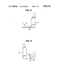
- FIGS. 3 and 4 The improved auto body side sill holding means are shown in FIGS. 3 and 4.
- a first side sill holding means which is constituted by an upright member 25 which is positioned inwardly of the respective auto body side sill 23 and a base member 26 which rests on the supporting member 17a extending inwardly from the lower end of the respective hanger arms on one side of the conveyor line, the right-hand side as viewed in FIG. 2.
- the base member 26 has a V-shaped notch or groove 27 therein which has a slightly flattened bottom 27a.
- the auto body side sill 23 engages in the groove, it is in a fixed position relative to the holding means, and, since the holding means is firmly attached to the support member 17a, the side sill and therefore the auto body is in a fixed position relative to the overall hanger arm frame structure of the conveyor.
- the auto body side sill 23 is held against lateral movement by the engagement of the edge of the sill 23 in the flat bottom of the V-shaped groove.
- Clamp means 40 is provided along one side of the conveyor path for preventing pivotal movement of the hanger arms 17 supporting the base members 26 having the V-shaped grooves 27 therein.
- the clamp means 40 can comprise a pair of V-shaped clamping members 41, each of which is movable by hydraulically actuated means 42 through suitable linkage to a position at which the clamping member 41 engages a respective hanger arm 17 to prevent pivotal movement thereof.
- the first side sill holding means can be held firmly in a desired lateral position by the clamp means 40.
- a second side sill holding means which also has an upright member 28 which is positioned inwardly of the respective auto body side sill 23 and a base member 29.
- a projection 30 On the end of the base member 29 which projects outwardly away from the center of the conveyor is a projection 30, and the outside face 31 thereof, which faces toward the line along which the conveyor runs, is angled downwardly and inwardly of the conveyor.
- the side sill 23 on the right hand side of the auto body rests simply on the flat upper surface of the base member 29, and can take a position anywhere along this flat surface depending upon the dimension between the side sills and the distance between the two holding means.
- the side sill 23 on the left side thereof will be positioned slightly to the left of the position for the preceding auto body. Further, if the hanger arm frame has become slightly distorted for some reason, the side sill 23 on the left side of the auto body is free to rest anywhere along the flat surface of the base member so as to accommodate the distortion.
- the bottom edges of the side sills 23 will both be at the same level, i.e. one in the bottom of the V-shaped groove, and the other on the upper surface of the base member 29, which are both at the same level, so that the auto body will not be tilted.
- the side sill on the right side of the auto body is always held at a position exactly the same distance from the hanger arm 17 on that side of the conveyor, the auto body will always be precisely positioned relative to the hanger arm frame along the conveyor apparatus.
- robots and the like which operate on the auto body will be controllable to move to exactly the same positions for each of the auto bodies to perform the work thereon in precisely the same locations for each auto body.
Abstract
Description
Claims (4)
Priority Applications (2)
| Application Number | Priority Date | Filing Date | Title |
|---|---|---|---|
| US07/239,614 US4909155A (en) | 1988-08-31 | 1988-08-31 | Auto body holding means for auto body conveyor apparatus with side sill holding means that accepts different sized side sills |
| JP1228179A JP2815188B2 (en) | 1988-08-31 | 1989-08-31 | Car body conveyor device |
Applications Claiming Priority (1)
| Application Number | Priority Date | Filing Date | Title |
|---|---|---|---|
| US07/239,614 US4909155A (en) | 1988-08-31 | 1988-08-31 | Auto body holding means for auto body conveyor apparatus with side sill holding means that accepts different sized side sills |
Publications (1)
| Publication Number | Publication Date |
|---|---|
| US4909155A true US4909155A (en) | 1990-03-20 |
Family
ID=22902933
Family Applications (1)
| Application Number | Title | Priority Date | Filing Date |
|---|---|---|---|
| US07/239,614 Expired - Fee Related US4909155A (en) | 1988-08-31 | 1988-08-31 | Auto body holding means for auto body conveyor apparatus with side sill holding means that accepts different sized side sills |
Country Status (2)
| Country | Link |
|---|---|
| US (1) | US4909155A (en) |
| JP (1) | JP2815188B2 (en) |
Cited By (4)
| Publication number | Priority date | Publication date | Assignee | Title |
|---|---|---|---|---|
| US5240103A (en) * | 1991-09-26 | 1993-08-31 | Mitsubishi Jidosha Kogyo Kabushiki Kaisha | Work conveying system for use in car body assembling line |
| US5379701A (en) * | 1992-08-03 | 1995-01-10 | Toyota Jidosha Kabushiki Kaisha | Seat apparatus having movable seat used by worker in installing parts within automobile body |
| US6210284B1 (en) * | 1998-09-08 | 2001-04-03 | Oriental Sangyo Co., Ltd. | Rides conveying park-goers in their own motor vehicles |
| CN101139043B (en) * | 2007-09-27 | 2010-10-06 | 重庆长安汽车股份有限公司 | Holding tool shared quick changing support of the vehicle final assembly conveying system |
Citations (5)
| Publication number | Priority date | Publication date | Assignee | Title |
|---|---|---|---|---|
| US3926125A (en) * | 1974-02-20 | 1975-12-16 | Redman Fisher Eng Ltd | Power and free conveyor |
| JPS5521347A (en) * | 1978-08-01 | 1980-02-15 | Tsubakimoto Chain Co | Hanger for overhead conveyor |
| JPS55101509A (en) * | 1979-01-24 | 1980-08-02 | Nissan Motor Co Ltd | Arm opening controller for car body conveyance hanger |
| JPS5927979A (en) * | 1981-12-21 | 1984-02-14 | Kao Corp | Refrigerant additive and refrigerant composition |
| US4464998A (en) * | 1982-03-25 | 1984-08-14 | Nakanishi Metal Works Co., Ltd. | Hanger device for trolley conveyor |
-
1988
- 1988-08-31 US US07/239,614 patent/US4909155A/en not_active Expired - Fee Related
-
1989
- 1989-08-31 JP JP1228179A patent/JP2815188B2/en not_active Expired - Lifetime
Patent Citations (5)
| Publication number | Priority date | Publication date | Assignee | Title |
|---|---|---|---|---|
| US3926125A (en) * | 1974-02-20 | 1975-12-16 | Redman Fisher Eng Ltd | Power and free conveyor |
| JPS5521347A (en) * | 1978-08-01 | 1980-02-15 | Tsubakimoto Chain Co | Hanger for overhead conveyor |
| JPS55101509A (en) * | 1979-01-24 | 1980-08-02 | Nissan Motor Co Ltd | Arm opening controller for car body conveyance hanger |
| JPS5927979A (en) * | 1981-12-21 | 1984-02-14 | Kao Corp | Refrigerant additive and refrigerant composition |
| US4464998A (en) * | 1982-03-25 | 1984-08-14 | Nakanishi Metal Works Co., Ltd. | Hanger device for trolley conveyor |
Cited By (4)
| Publication number | Priority date | Publication date | Assignee | Title |
|---|---|---|---|---|
| US5240103A (en) * | 1991-09-26 | 1993-08-31 | Mitsubishi Jidosha Kogyo Kabushiki Kaisha | Work conveying system for use in car body assembling line |
| US5379701A (en) * | 1992-08-03 | 1995-01-10 | Toyota Jidosha Kabushiki Kaisha | Seat apparatus having movable seat used by worker in installing parts within automobile body |
| US6210284B1 (en) * | 1998-09-08 | 2001-04-03 | Oriental Sangyo Co., Ltd. | Rides conveying park-goers in their own motor vehicles |
| CN101139043B (en) * | 2007-09-27 | 2010-10-06 | 重庆长安汽车股份有限公司 | Holding tool shared quick changing support of the vehicle final assembly conveying system |
Also Published As
| Publication number | Publication date |
|---|---|
| JP2815188B2 (en) | 1998-10-27 |
| JPH0367776A (en) | 1991-03-22 |
Similar Documents
| Publication | Publication Date | Title |
|---|---|---|
| US7296521B2 (en) | Conveyance apparatus using movable body | |
| US4475462A (en) | Tiltable hanger apparatus | |
| US3528539A (en) | Overhead conveyor apparatus | |
| US4909155A (en) | Auto body holding means for auto body conveyor apparatus with side sill holding means that accepts different sized side sills | |
| AU712725B2 (en) | A belt steering assembly for centering of conveyor belts | |
| US4470593A (en) | Gripper arrangement for sheet-machining installations | |
| JPS632842B2 (en) | ||
| US5257899A (en) | Transfer feeder | |
| JPH0464602A (en) | Flexible rail | |
| GB2077681A (en) | Side suspensions conveyor system for poultry | |
| US2792927A (en) | Load carriers for use in overhead trolley conveyor systems | |
| JPH0511099Y2 (en) | ||
| JPS62163854A (en) | Hanging carrying facility | |
| US5058730A (en) | Automatic dump actuator conveyor system | |
| JPH0791037B2 (en) | Lifting and tilting device for transported objects | |
| US5215183A (en) | Automatic dump actuator conveyor system | |
| JPS5916340Y2 (en) | Goods conveyance device | |
| JP2000094243A (en) | Swing preventing device for engine assembly | |
| JPS643619Y2 (en) | ||
| JP2735342B2 (en) | Hanging transfer equipment with cradle changing device | |
| US4960201A (en) | Automatic dump actuator conveyor system | |
| JPH03178859A (en) | Attitude control device for conveyed object in overhead conveyer | |
| JPS637479Y2 (en) | ||
| JPH04128403A (en) | Flexible rail | |
| JPH0615586A (en) | Attitude holding mechanism of conveyor |
Legal Events
| Date | Code | Title | Description |
|---|---|---|---|
| AS | Assignment |
Owner name: MAZDA MOTOR MANUFACTURING (USA) CORPORATION, 1 MAZ Free format text: ASSIGNMENT OF ASSIGNORS INTEREST.;ASSIGNOR:KATAYAMA, SHINJI;REEL/FRAME:004959/0267 Effective date: 19880915 Owner name: MAZDA MOTOR MANUFACTURING (USA) CORPORATION, MICHI Free format text: ASSIGNMENT OF ASSIGNORS INTEREST;ASSIGNOR:KATAYAMA, SHINJI;REEL/FRAME:004959/0267 Effective date: 19880915 |
|
| AS | Assignment |
Owner name: AUTOALLIANCE INTERNATIONAL, INC., MICHIGAN Free format text: CHANGE OF NAME;ASSIGNOR:MAZDA MOTOR MANUFACTURING (USA) CORPORATION;REEL/FRAME:006445/0822 Effective date: 19930210 |
|
| FPAY | Fee payment |
Year of fee payment: 4 |
|
| FEPP | Fee payment procedure |
Free format text: PAYOR NUMBER ASSIGNED (ORIGINAL EVENT CODE: ASPN); ENTITY STATUS OF PATENT OWNER: LARGE ENTITY |
|
| REMI | Maintenance fee reminder mailed | ||
| LAPS | Lapse for failure to pay maintenance fees | ||
| FP | Lapsed due to failure to pay maintenance fee |
Effective date: 19980325 |
|
| STCH | Information on status: patent discontinuation |
Free format text: PATENT EXPIRED DUE TO NONPAYMENT OF MAINTENANCE FEES UNDER 37 CFR 1.362 |