US4907943A - Method and apparatus for assessing thrust loads on engine bearings - Google Patents
Method and apparatus for assessing thrust loads on engine bearings Download PDFInfo
- Publication number
- US4907943A US4907943A US07/198,330 US19833088A US4907943A US 4907943 A US4907943 A US 4907943A US 19833088 A US19833088 A US 19833088A US 4907943 A US4907943 A US 4907943A
- Authority
- US
- United States
- Prior art keywords
- axial
- rotor
- value
- bearing
- pressure
- Prior art date
- Legal status (The legal status is an assumption and is not a legal conclusion. Google has not performed a legal analysis and makes no representation as to the accuracy of the status listed.)
- Expired - Lifetime
Links
Images


Classifications
-
- F—MECHANICAL ENGINEERING; LIGHTING; HEATING; WEAPONS; BLASTING
- F01—MACHINES OR ENGINES IN GENERAL; ENGINE PLANTS IN GENERAL; STEAM ENGINES
- F01D—NON-POSITIVE DISPLACEMENT MACHINES OR ENGINES, e.g. STEAM TURBINES
- F01D3/00—Machines or engines with axial-thrust balancing effected by working-fluid
- F01D3/04—Machines or engines with axial-thrust balancing effected by working-fluid axial thrust being compensated by thrust-balancing dummy piston or the like
Definitions
- This invention relates to gas turbine engine controllers and more particularly to gas turbine engine controllers which measure and adjust thrust loads on rotor bearings.
- Thrust loads are determined by internal engine air flow, internal engine compartment air pressures, seals and seal locations, as well as airfoil aerodynamic loads. All are integral components of the summed load on the rotor bearings and are configured to load the axial bearings only within a selected range. Advanced engine designs endeavor to reduce the magnitude and range of the bearing load in order to achieve lower bearing weights and longer bearing lifetimes.
- each separate engine type must have that bearing support structure modified to receive a specifically designed load cell support ring.
- the support ring is installed only for test purposes and must be removed before placing the engine in service. This measurement technique is elaborate and very expensive and is not available on engines in service.
- the special instrumentation previously required to measure axial thrust load on rotor bearings includes mechanical strain gauges that are configured into a special bearing support ring.
- the support ring must be physically installed in the bearing assembly during thrust load measurements and removed prior to placing the engine in service.
- the physical installation of the instrumented bearing support ring required additional radial clearance of the bearing outer race. This alters the rotor system dynamics response and may limit the operating envelope of the engine. Smaller engines present a more difficult problem since the clearances within these engines are themselves smaller which makes load deviations more sensitive to manufacturing tolerances. Also, small engines have less available space for instrumentation.
- the thrust loads measured by these strain gauges are small enough in magnitude to be outside the load range of conventional mechanical load cell techniques.
- known methods for measuring axial thrust loads must further differentiate between bearing loads induced by axial thrust and thermally induced loads.
- Another object of the present invention is to provide a method and apparatus for assessing thrust loads on gas turbine engine bearings without affecting rotor bearing radial support clearance.
- Another object of the present invention is to provide a method and apparatus for assessing thrust loads on gas turbine engine bearings while those engines are in service.
- Another object of the present invention is to provide a method and apparatus for assessing thrust loads on gas turbine engine bearings and adjusting the bearing thrust load during scheduled maintenance operations.
- Still another object of the present invention is to provide a method and apparatus for adjusting axial trim cavity pressure to provide continuous regulation of axial thrust loads on gas turbine engine rotor bearings.
- an apparatus for use in a gas turbine engine having a rotor positioned along a longitudinal axis by an axial bearing, said apparatus indicating axial rotor loads without a load cell support ring, and including a measurement means for providing signals indicative of the longitudinal position of the rotor in the bearings. Also included is a computer that receives the measured rotor position signals and generates therefrom signals indicative of axial thrust load on the rotor.
- an apparatus for use in a gas turbine engine having a rotor positioned along the longitudinal axis by an axial bearing said apparatus for selecting longitudinal rotor position and including a measuring apparatus that provides signals indicative of the longitudinal position of the rotor in the bearing as well as a displacement mechanism which selectively displaces the rotor along the longitudinal axis in response to control signals.
- the apparatus further includes a controller which receives the measured rotor position signals and computes axial load on the rotor. Also, the controller compares the measured rotor position signals with the load signals and provides therefrom control signals to the rotor displacement mechanism to select an axial rotor position.
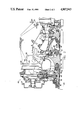
- FIG. 1 is a simplified cross sectional illustration of a gas turbine engine with a controller having an apparatus for determining thrust loads on engine bearings in accordance with the present invention.
- FIG. 2 is an expanded, sectional illustration of an upper, central portion of the jet engine shown in FIG. 1.
- FIG. 3 is a diagrammatic illustration relating rotor axial position to trim cavity pressure.
- FIG. 4 is a diagrammatic illustration relating engine rotor thrust load to trim cavity pressure.
- FIG. 1 there is illustrated, in schematic form, a gas turbine engine 10 which is a conventional three spool type having a spool 11 including a power turbine 17 driving the fan 15 and a spool 12 including a low turbine 13 driving a low compressor 14 and a spool 16 having a high pressure compressor 18 and high pressure turbine 20.
- a conventional burner 22, disposed between the compressor exit and turbine inlet serves to heat and accelerate the gas sufficiently to power the turbines and generate thrust.
- gas moves through the engine from left to right by means of a primary engine gas flow path 23.
- the engine contains additional, secondary gas paths not detailed herein. These secondary paths channel the engine internal gas flow.
- the high pressure spool, low pressure spool and fan spool are disposed along a longitudinal axis 24 of the engine.
- the spools are not mechanically connected to each other, but rotate independently.
- the engine may or may not also include an augmentor (not illustrated) receiving discharged gas from the power turbine. The gas exits the engine via an exhaust nozzle 26.
- the pilot controls engine power by means of throttle level 30.
- the angle of the throttle lever as well as the rate of change of throttle lever angle is determinative of the amount of power supplied by the engine. Signals indicative thereof are provided on lines 32 to the controller 33.
- a plurality of engine sensors, indicated schematically at 34, provide the controller with corresponding engine parameter signals. Control signals are output to operate the engine on lines 36, 38.
- FIG. 2 there is illustrated in section an upper, central portion of the jet engine 10 of FIG. 1.
- Spools 11, 12 and 16 rotate about axis 24.
- a high spool axial thrust trim cavity 44 is located downstream of the high compressor (impeller) 18 between labyrinth seals 46 and 48.
- trim cavity 44 is pressurized with air extracted upstream of combuster 50 and throttled through control area 52 to pressurize the trim cavity 44 at a pressure value that is intermediate to the high compressor exit total and static pressures.
- Air line 54 is also routed from the trim cavity to the exterior of the engine, and externally connected to air line 55 which is valved to metered high pressure air extracted from the engine burner case.
- air lines 54,55 are only schematically shown and are conventionally configured on the engine case in the preferred embodiment.
- Thrust bearing 56 is conventional and is comprised of outer and inner races 58 and 60 and a plurality of balls, such as ball 61.
- the loading on the bearing is varied so that its axial position changes.
- the high spool axial thrust load trim control valves 62 and 64 are closed, and the high spool axial thrust load is selected to be at its base or initial load condition.
- the null load position is approached by bleeding air to the exterior of the engine through control valve 62.
- the thrust bearing 56 is preferably rearward loaded on the outer race aft surface by a select amount (approximately 417 lbs.) at the bearing's aero-design point.
- the high spool axial thrust trim cavity pressure is increased by opening control valve 64 to increase forward loading on the spool.
- the thrust bearing ball 61 shifts forward, allowing the spool axial position to move on the order of 6 to 12 thousands of an inch.
- the position of the thrust bearing ball is measured by proximity probe 66 which, in the preferred embodiment, comprises an electromagnetic sensor positioned adjacent to the rotating bearing elements.
- Probe 66 provides signals indicative of the spool axial position to controller 33 which then computes the deviation in thrust trim cavity pressure needed to shift the bearing ball to a position in between the forward-to-aft bearing races, defined as the null position, which also corresponds to the null load condition.
- the bearing is subjected to zero axial load at the null load condition.
- the deviation in thrust trim cavity pressure is defined as the difference between the trim cavity pressure corresponding to the base load and the trim cavity pressure at the null load condition.
- the load deviation is defined to be the product of the thrust trim cavity pressure deviation and the trim cavity axial area.
- the ball bearing axial load at the base condition is determined, and is equal to the load deviation.
- the deviation in axial thrust load is the difference between the high spool axial load prior to the opening of control valve 64 and that load value measured when the spool is moved to the null load position.
- the axial thrust load for the high spool base condition can be changed by altering the pressure of control area 52 by means of throttled air extracted upstream of the burner.
- the control area 52 consists of 13, 0.25 inch diameter threaded holes selectively plugged to establish the base load.
- the high spool axial thrust load adjustment air lines 54 and 55 are external to the engine, and, together with control valves 62 and 64, comprise special test equipment, for engines such as shown in FIG. 1 that do not provide continuous and interactive axial load control. Once the calibration procedure detailed above has been completed, the special test equipment is removed from the engine by simply capping the lines where they exit the engine case.
- a low spool axial thrust trim cavity 68 is located aft or downstream of the low turbine 13 between labyrinth seals 70 and 72.
- Low spool axial trim cavity 68 is normally pressurized with air bled from around the bore of the low pressure turbine and combined with low pressure compressor (LPC) buffer air from seal 72 which discharges air into the primary engine gas flow path through seal 70.
- LPC low pressure compressor
- the low spool is designed to be forward loaded approximately 525 lbs. in the preferred embodiment. This load is resisted by low spool thrust bearing 76.
- a second proximity probe 78 similar to the first is positioned to measure changes in thrust bearing 76 position in a manner similar to that described hereinabove with respect to thrust bearing 56.
- the low spool axial thrust trim cavity is also configured with special test equipment air lines 80,81, which are outside of the engine, as are air line control valves 82 and 84.
- the low spool thrust trim cavity pressure can be reduced by bleeding air to the exterior of the engine through control valve 84. This reduction of air pressure reduces the forward load on the spool in the preferred embodiment.
- Axial thrust load on the low spool and the correlation between thrust trim cavity pressure and spool position are determined in the manner described hereinabove with respect to the high spool.
- the low spool axial thrust load is the product of the axial area of trim cavity 68 and the cavity pressure deviation to achieve the null pressure.
- the null load position is approached by pressurizing trim cavity 68 with low pressure compressor (LPC) air via control valve 82.
- LPC low pressure compressor
- FIG. 3 is a diagrammatic illustration showing the axial position of a given rotor and the corresponding thrust trim cavity pressure as the cavity pressure is cycled over time.
- Curve 86 corresponds to the rotor axial position
- curve 88 corresponds to the thrust trim cavity pressure.
- each thrust bearing is instrumented with a proximity probe to indicate ball axial location in a thrust bearing and corresponding rotor axial position.
- the thrust trim cavity pressure is cycled to find null load points 90, and 92.
- spool axial load can be computed by the controller as the product of the thrust trim cavity pressure deviation and the cavity axial area.
- axes 94 and 96 correspond to rotor thrust load and thrust trim cavity pressure, respectively.
- Curve 98 corresponds to the computed axial thrust load as a function of thrust cavity pressure.
- a specific thrust cavity pressure corresponds to a specific rotor thrust load.
- the bearing axial thrust load assessment is required during the engine development program. Engines that are sensitive to bearing axial thrust loads can have those thrust loads adjusted by altering control area 52 pressure during the initial or "green" engine run and can also have axial thrust load adjustments performed during scheduled maintenance inspections to compensate for engine deterioration.
- a controller 33 configured to provide continuous interactive axial load control preferably comprises a conventional processor and sufficient memory means as is necessaryy to perform the functions described herein.
- the controller receives bearing ball position signals from the probes 66 and 78 which indicate the axial positions of the rotors.
- the controller correlates the measured bearing ball positions to the respective cavity trim pressures and computes rotor thrust load using conventional algorithms in accordance with the relationships outlined hereinabove. These computed relationships are stored in the controller and comprise a thrust load schedule.
- the controller is programmed during engine operation to select the desired trim cavity pressures and hence the desired thrust loads.
- the controller generates corresponding signals to open and close programmable control valves by an amount needed to produce the desired pressures in the trim cavities.
- controller 33 may be programmed to simulate the trim cavity pressure deviation and corresponding deviation in bearing load using known numerical models. These models analyze engine internal gas flow and pressure as comprehensive system and are more precise than the method for computing trim cavity pressure and bearing load deviations detailed above, since they account for secondary effects on gas pressure changes within the engine.
Abstract
Description
Claims (3)
Priority Applications (1)
| Application Number | Priority Date | Filing Date | Title |
|---|---|---|---|
| US07/198,330 US4907943A (en) | 1988-05-25 | 1988-05-25 | Method and apparatus for assessing thrust loads on engine bearings |
Applications Claiming Priority (1)
| Application Number | Priority Date | Filing Date | Title |
|---|---|---|---|
| US07/198,330 US4907943A (en) | 1988-05-25 | 1988-05-25 | Method and apparatus for assessing thrust loads on engine bearings |
Publications (1)
| Publication Number | Publication Date |
|---|---|
| US4907943A true US4907943A (en) | 1990-03-13 |
Family
ID=22732932
Family Applications (1)
| Application Number | Title | Priority Date | Filing Date |
|---|---|---|---|
| US07/198,330 Expired - Lifetime US4907943A (en) | 1988-05-25 | 1988-05-25 | Method and apparatus for assessing thrust loads on engine bearings |
Country Status (1)
| Country | Link |
|---|---|
| US (1) | US4907943A (en) |
Cited By (19)
| Publication number | Priority date | Publication date | Assignee | Title |
|---|---|---|---|---|
| US5735666A (en) * | 1996-12-31 | 1998-04-07 | General Electric Company | System and method of controlling thrust forces on a thrust bearing in a rotating structure of a gas turbine engine |
| US5862666A (en) * | 1996-12-23 | 1999-01-26 | Pratt & Whitney Canada Inc. | Turbine engine having improved thrust bearing load control |
| US6035627A (en) * | 1998-04-21 | 2000-03-14 | Pratt & Whitney Canada Inc. | Turbine engine with cooled P3 air to impeller rear cavity |
| US6067791A (en) * | 1997-12-11 | 2000-05-30 | Pratt & Whitney Canada Inc. | Turbine engine with a thermal valve |
| US6227801B1 (en) | 1999-04-27 | 2001-05-08 | Pratt & Whitney Canada Corp. | Turbine engine having improved high pressure turbine cooling |
| US6457933B1 (en) | 2000-12-22 | 2002-10-01 | General Electric Company | Methods and apparatus for controlling bearing loads within bearing assemblies |
| US20060032230A1 (en) * | 2004-08-13 | 2006-02-16 | Freese Richard A | Rocket augmentation for combined cycle turboaccelerator jet engine |
| US20070122265A1 (en) * | 2005-11-30 | 2007-05-31 | General Electric Company | Rotor thrust balancing apparatus and method |
| ITMI20110682A1 (en) * | 2011-04-21 | 2012-10-22 | Exergy Orc S R L | EXPANSION TURBINE AND METHOD TO COMPENSATE THE AXIAL PUSH IN AN EXPANSION TURBINE |
| US20130071242A1 (en) * | 2011-09-16 | 2013-03-21 | Joseph T. Caprario | Thrust bearing system with inverted non-contacting dynamic seals for gas turbine engine |
| EP2246528A3 (en) * | 2009-04-24 | 2014-05-14 | Pratt & Whitney Canada Corp. | Load distribution system for gas turbine engine |
| EP2206902A3 (en) * | 2008-12-23 | 2015-12-02 | General Electric Company | Turbine cooling air from a centrifugal compressor |
| EP2206882A3 (en) * | 2008-12-23 | 2015-12-02 | General Electric Company | Centrifugal Compressor Forward Thrust and Turbine Cooling Apparatus |
| EP3015659A1 (en) * | 2014-10-29 | 2016-05-04 | Rolls-Royce plc | Bearing apparatus for a gas turbine and method of determining the load on such a bearing apparatus |
| US20170134154A1 (en) * | 2015-11-09 | 2017-05-11 | Thomas G. Pratt | Monitoring rotating machinery using radio frequency probes |
| CN107120190A (en) * | 2016-02-24 | 2017-09-01 | 通用电气公司 | Turbogenerator injector throat controls |
| US10167734B2 (en) | 2012-09-27 | 2019-01-01 | United Technologies Corporation | Buffer airflow to bearing compartment |
| US20200095941A1 (en) * | 2018-09-25 | 2020-03-26 | United Technologies Corporation | Thrust balance control with differential power extraction |
| US10605841B2 (en) | 2015-11-09 | 2020-03-31 | University Of Notre Dame Du Lac | Coherent signal analyzer |
Citations (8)
| Publication number | Priority date | Publication date | Assignee | Title |
|---|---|---|---|---|
| US1298630A (en) * | 1918-06-13 | 1919-03-25 | Westinghouse Gear & Dynamometer Company | Thrust-bearing and dynamometer. |
| US2530477A (en) * | 1948-09-22 | 1950-11-21 | Ostmar Frans Eric Ossian | Means for balancing the axial thrust of elastic fluid compressors and turbines of the axial flow type |
| US2647684A (en) * | 1947-03-13 | 1953-08-04 | Rolls Royce | Gas turbine engine |
| US2746671A (en) * | 1950-04-14 | 1956-05-22 | United Aircraft Corp | Compressor deicing and thrust balancing arrangement |
| US3433020A (en) * | 1966-09-26 | 1969-03-18 | Gen Electric | Gas turbine engine rotors |
| US3828610A (en) * | 1970-01-07 | 1974-08-13 | Judson S Swearingen | Thrust measurement |
| US4578018A (en) * | 1983-06-20 | 1986-03-25 | General Electric Company | Rotor thrust balancing |
| US4730977A (en) * | 1986-12-31 | 1988-03-15 | General Electric Company | Thrust bearing loading arrangement for gas turbine engines |
-
1988
- 1988-05-25 US US07/198,330 patent/US4907943A/en not_active Expired - Lifetime
Patent Citations (8)
| Publication number | Priority date | Publication date | Assignee | Title |
|---|---|---|---|---|
| US1298630A (en) * | 1918-06-13 | 1919-03-25 | Westinghouse Gear & Dynamometer Company | Thrust-bearing and dynamometer. |
| US2647684A (en) * | 1947-03-13 | 1953-08-04 | Rolls Royce | Gas turbine engine |
| US2530477A (en) * | 1948-09-22 | 1950-11-21 | Ostmar Frans Eric Ossian | Means for balancing the axial thrust of elastic fluid compressors and turbines of the axial flow type |
| US2746671A (en) * | 1950-04-14 | 1956-05-22 | United Aircraft Corp | Compressor deicing and thrust balancing arrangement |
| US3433020A (en) * | 1966-09-26 | 1969-03-18 | Gen Electric | Gas turbine engine rotors |
| US3828610A (en) * | 1970-01-07 | 1974-08-13 | Judson S Swearingen | Thrust measurement |
| US4578018A (en) * | 1983-06-20 | 1986-03-25 | General Electric Company | Rotor thrust balancing |
| US4730977A (en) * | 1986-12-31 | 1988-03-15 | General Electric Company | Thrust bearing loading arrangement for gas turbine engines |
Cited By (31)
| Publication number | Priority date | Publication date | Assignee | Title |
|---|---|---|---|---|
| US5862666A (en) * | 1996-12-23 | 1999-01-26 | Pratt & Whitney Canada Inc. | Turbine engine having improved thrust bearing load control |
| US5735666A (en) * | 1996-12-31 | 1998-04-07 | General Electric Company | System and method of controlling thrust forces on a thrust bearing in a rotating structure of a gas turbine engine |
| US6067791A (en) * | 1997-12-11 | 2000-05-30 | Pratt & Whitney Canada Inc. | Turbine engine with a thermal valve |
| US6035627A (en) * | 1998-04-21 | 2000-03-14 | Pratt & Whitney Canada Inc. | Turbine engine with cooled P3 air to impeller rear cavity |
| US6227801B1 (en) | 1999-04-27 | 2001-05-08 | Pratt & Whitney Canada Corp. | Turbine engine having improved high pressure turbine cooling |
| US6457933B1 (en) | 2000-12-22 | 2002-10-01 | General Electric Company | Methods and apparatus for controlling bearing loads within bearing assemblies |
| US20060032230A1 (en) * | 2004-08-13 | 2006-02-16 | Freese Richard A | Rocket augmentation for combined cycle turboaccelerator jet engine |
| US7305816B2 (en) * | 2004-08-13 | 2007-12-11 | United Technologies Corporation | Rocket augmentation for combined cycle turboaccelerator jet engine |
| US20070122265A1 (en) * | 2005-11-30 | 2007-05-31 | General Electric Company | Rotor thrust balancing apparatus and method |
| EP1793081A2 (en) * | 2005-11-30 | 2007-06-06 | General Electric Company | Rotor thrust balancing apparatus and method |
| JP2007154888A (en) * | 2005-11-30 | 2007-06-21 | General Electric Co <Ge> | Rotor thrust balancing device and method |
| EP1793081A3 (en) * | 2005-11-30 | 2007-10-24 | General Electric Company | Rotor thrust balancing apparatus and method |
| EP2206882A3 (en) * | 2008-12-23 | 2015-12-02 | General Electric Company | Centrifugal Compressor Forward Thrust and Turbine Cooling Apparatus |
| EP2206902A3 (en) * | 2008-12-23 | 2015-12-02 | General Electric Company | Turbine cooling air from a centrifugal compressor |
| EP2246528A3 (en) * | 2009-04-24 | 2014-05-14 | Pratt & Whitney Canada Corp. | Load distribution system for gas turbine engine |
| ITMI20110682A1 (en) * | 2011-04-21 | 2012-10-22 | Exergy Orc S R L | EXPANSION TURBINE AND METHOD TO COMPENSATE THE AXIAL PUSH IN AN EXPANSION TURBINE |
| US10119476B2 (en) * | 2011-09-16 | 2018-11-06 | United Technologies Corporation | Thrust bearing system with inverted non-contacting dynamic seals for gas turbine engine |
| US10815903B2 (en) | 2011-09-16 | 2020-10-27 | Raytheon Technologies Corporation | Thrust bearing system with inverted non-contacting dynamic seals for gas turbine engine |
| US20130071242A1 (en) * | 2011-09-16 | 2013-03-21 | Joseph T. Caprario | Thrust bearing system with inverted non-contacting dynamic seals for gas turbine engine |
| US10167734B2 (en) | 2012-09-27 | 2019-01-01 | United Technologies Corporation | Buffer airflow to bearing compartment |
| US9664593B2 (en) | 2014-10-29 | 2017-05-30 | Rolls-Royce Plc | Bearing apparatus |
| EP3015659A1 (en) * | 2014-10-29 | 2016-05-04 | Rolls-Royce plc | Bearing apparatus for a gas turbine and method of determining the load on such a bearing apparatus |
| US20170134154A1 (en) * | 2015-11-09 | 2017-05-11 | Thomas G. Pratt | Monitoring rotating machinery using radio frequency probes |
| US10280787B2 (en) * | 2015-11-09 | 2019-05-07 | University Of Notre Dame Du Lac | Monitoring rotating machinery using radio frequency probes |
| US10605841B2 (en) | 2015-11-09 | 2020-03-31 | University Of Notre Dame Du Lac | Coherent signal analyzer |
| JP2017198188A (en) * | 2016-02-24 | 2017-11-02 | ゼネラル・エレクトリック・カンパニイ | Turbine engine ejector throat control |
| EP3219956A3 (en) * | 2016-02-24 | 2017-11-29 | General Electric Company | Turbine engine ejector throat control |
| CN107120190A (en) * | 2016-02-24 | 2017-09-01 | 通用电气公司 | Turbogenerator injector throat controls |
| CN107120190B (en) * | 2016-02-24 | 2019-01-22 | 通用电气公司 | Gas-turbine unit |
| US20200095941A1 (en) * | 2018-09-25 | 2020-03-26 | United Technologies Corporation | Thrust balance control with differential power extraction |
| US10920671B2 (en) * | 2018-09-25 | 2021-02-16 | Raytheon Technologies Corporation | Thrust balance control with differential power extraction |
Similar Documents
| Publication | Publication Date | Title |
|---|---|---|
| US4907943A (en) | Method and apparatus for assessing thrust loads on engine bearings | |
| US10794275B2 (en) | Multi-circuit buffer system for a gas turbine engine | |
| US10260425B2 (en) | Leak detection, isolation and accommodation assembly for gas turbine engines | |
| EP2954297B1 (en) | Auto testing system for a gas turbine | |
| US4294069A (en) | Exhaust nozzle control and core engine fuel control for turbofan engine | |
| US5760289A (en) | System for balancing loads on a thrust bearing of a gas turbine engine rotor and process for calibrating control therefor | |
| US20070137214A1 (en) | Engine arrangements and control | |
| EP3168428B1 (en) | A system and method of calibrating case cooling for a gas turbine engine | |
| US4594849A (en) | Apparatus for synthesizing control parameters | |
| JP2017155744A (en) | Method and system for piping failure detection | |
| Ainsworth et al. | A transient flow facility for the study of the thermofluid-dynamics of a full stage turbine under engine representative conditions | |
| US4894782A (en) | Diagnostic system for determining engine start bleed strap failure | |
| EP1482150B1 (en) | Method and system of synthesizing turbine inlet temperature of a turbo machine | |
| US4050306A (en) | Method and apparatus for measuring pressures | |
| CN114719809A (en) | Method and apparatus for real-time clearance assessment using pressure measurements | |
| Orme et al. | Flight assessment of the onboard propulsion system model for the Performance Seeking Control algorithm of an F-15 aircraft | |
| Cline et al. | High pressure compressor component performance report | |
| CN113383154A (en) | Method for monitoring the operating state of a hydraulic machine unit | |
| US20190010821A1 (en) | Systems and methods for virtual clearance measurement in a gas turbine | |
| GB2338793A (en) | Force measurement system for a jet engine | |
| Delaney et al. | A model propulsion simulator for evaluating counter rotating blade characteristics | |
| Haldeman et al. | Fully-Cooled Single Stage HP Transonic Turbine: Part I—Influence of Cooling Mass Flow Variations and Inlet Temperature Profiles on Blade Internal and External Aerodynamics | |
| EP4223997A1 (en) | Method and apparatus for measuring compressor bleed flow | |
| US20240110489A1 (en) | Systems and methods for identifying a condition of gas turbine engine seals | |
| EP3693664A1 (en) | Method for operating a gas turbine |
Legal Events
| Date | Code | Title | Description |
|---|---|---|---|
| AS | Assignment |
Owner name: UNITED TECHNOLOGIES CORPORATION, UNITED TECHNOLOGI Free format text: ASSIGNMENT OF ASSIGNORS INTEREST.;ASSIGNOR:KELCH, GEORGE W.;REEL/FRAME:004923/0721 Effective date: 19880517 Owner name: UNITED TECHNOLOGIES CORPORATION, A CORP. OF DE,CON Free format text: ASSIGNMENT OF ASSIGNORS INTEREST;ASSIGNOR:KELCH, GEORGE W.;REEL/FRAME:004923/0721 Effective date: 19880517 |
|
| AS | Assignment |
Owner name: UNITED TECHNOLOGIES CORPORATION, A CORP. OF DELAWA Free format text: RE-RECORD TO CORRECT THE EXECUTION DATE OF APPLICATION;ASSIGNOR:KELCH, GEORGE W.;REEL/FRAME:005070/0915 Effective date: 19880517 |
|
| STCF | Information on status: patent grant |
Free format text: PATENTED CASE |
|
| FEPP | Fee payment procedure |
Free format text: PAYOR NUMBER ASSIGNED (ORIGINAL EVENT CODE: ASPN); ENTITY STATUS OF PATENT OWNER: LARGE ENTITY |
|
| FPAY | Fee payment |
Year of fee payment: 4 |
|
| FPAY | Fee payment |
Year of fee payment: 8 |
|
| FPAY | Fee payment |
Year of fee payment: 12 |
|
| FEPP | Fee payment procedure |
Free format text: PAYER NUMBER DE-ASSIGNED (ORIGINAL EVENT CODE: RMPN); ENTITY STATUS OF PATENT OWNER: LARGE ENTITY Free format text: PAYOR NUMBER ASSIGNED (ORIGINAL EVENT CODE: ASPN); ENTITY STATUS OF PATENT OWNER: LARGE ENTITY |