US4901756A - I/P converter with simulated compensation - Google Patents
I/P converter with simulated compensation Download PDFInfo
- Publication number
- US4901756A US4901756A US07/350,246 US35024689A US4901756A US 4901756 A US4901756 A US 4901756A US 35024689 A US35024689 A US 35024689A US 4901756 A US4901756 A US 4901756A
- Authority
- US
- United States
- Prior art keywords
- actuator
- converter
- drive
- load
- simulated
- Prior art date
- Legal status (The legal status is an assumption and is not a legal conclusion. Google has not performed a legal analysis and makes no representation as to the accuracy of the status listed.)
- Expired - Lifetime
Links
- 230000035945 sensitivity Effects 0.000 claims abstract description 3
- 230000001934 delay Effects 0.000 claims description 3
- 238000004088 simulation Methods 0.000 claims 2
- 230000001939 inductive effect Effects 0.000 description 5
- 238000010586 diagram Methods 0.000 description 3
- 230000002277 temperature effect Effects 0.000 description 3
- 230000001143 conditioned effect Effects 0.000 description 2
- RYGMFSIKBFXOCR-UHFFFAOYSA-N Copper Chemical compound [Cu] RYGMFSIKBFXOCR-UHFFFAOYSA-N 0.000 description 1
- 239000003990 capacitor Substances 0.000 description 1
- 230000005669 field effect Effects 0.000 description 1
Images
Classifications
-
- G—PHYSICS
- G05—CONTROLLING; REGULATING
- G05D—SYSTEMS FOR CONTROLLING OR REGULATING NON-ELECTRIC VARIABLES
- G05D16/00—Control of fluid pressure
- G05D16/20—Control of fluid pressure characterised by the use of electric means
- G05D16/2006—Control of fluid pressure characterised by the use of electric means with direct action of electric energy on controlling means
- G05D16/2013—Control of fluid pressure characterised by the use of electric means with direct action of electric energy on controlling means using throttling means as controlling means
-
- Y—GENERAL TAGGING OF NEW TECHNOLOGICAL DEVELOPMENTS; GENERAL TAGGING OF CROSS-SECTIONAL TECHNOLOGIES SPANNING OVER SEVERAL SECTIONS OF THE IPC; TECHNICAL SUBJECTS COVERED BY FORMER USPC CROSS-REFERENCE ART COLLECTIONS [XRACs] AND DIGESTS
- Y10—TECHNICAL SUBJECTS COVERED BY FORMER USPC
- Y10T—TECHNICAL SUBJECTS COVERED BY FORMER US CLASSIFICATION
- Y10T137/00—Fluid handling
- Y10T137/7722—Line condition change responsive valves
- Y10T137/7758—Pilot or servo controlled
- Y10T137/7761—Electrically actuated valve
Definitions
- This invention relates to current-to-pressure (I/P) converters.
- a current-to-pressure converter provides simulated compensation to avoid undesired reactive components or temperature effects found in an actuator load in the converter.
- the converter controls a line pressure according to a signal received by the converter indicating a desired pressure.
- the converter comprises sensing means for sensing the line pressure and the signal.
- the sensing means receive compensation and provide a compensated output representative of the line and desired pressures.
- the converter also comprises first driver means for providing an actuator drive as a function of the compensated output and an actuator controlling the line pressure as a function of the actuator drive.
- the actuator presents an actuator load to the actuator drive which has undesired parameters such as reactance and temperature sensitivity.
- the converter further comprises a simulated load simulating a desired portion of the actuator load, avoiding undesired reactance and temperature parameters of the actuator.
- the converter comprises second driver means for providing a simulated drive to the simulated load as a function of the compensated output.
- the second driver means further generates the compensation as a function of the simulated drive such that the compensation is representative of the actuator drive but isolated from the actuator load.
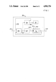
- FIG. 1 is a block diagram of a current to pressure converter according to the invention.
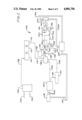
- FIG. 2 is a partial schematic, partial block diagram of a circuit according to the invention.
- FIG. 1 a block diagram of a first preferred embodiment of a current-to-pressure converter 50 is shown.
- the converter 50 controls a line pressure 52 according to signal 54 received by converter 50 indicating a desired pressure.
- Sensing means 56 sense the line pressure 52 and the signal 54.
- Sensing means 56 also receive compensation from a line 58 and provide a compensated output 62 representative of the line pressure 52 and the desired pressure indicated by signal 54.
- First driver means 64 provide an actuator drive 66 as a function of the compensated output 62.
- Actuator 68 controls the line pressure 52 as a function of the actuator drive 66, however the actuator 68 presents an actuator load 72 to the actuator drive 66 as indicated by arrow 74.
- Simulated load 76 simulates a desired portion of the actuator load 72.
- Second driver means 78 provide a simulated drive 82 to the simulated load 76 as a function of the compensated output 62.
- the second driver means 78 further generate the compensation 58 as a function of the simulated drive 82 such that the compensation 58 is representative of the actuator drive 66 but isolated from the actuator load 72.
- the compensated output 62 represents a difference between the line pressure 52 and the desired pressure as indicated by the signal 54.
- the compensation 58 slows the response of the compensated output 62 to changes in the difference between line pressure 52 and desired pressure.
- the compensation adapts the drive to be compatible with the gain and delay parameters of the actuator 68 and the sensor means 56.
- FIG. 2 a second preferred embodiment of the invention is shown at 100, adapting the present invention to a current-to-pressure converter such as shown in U.S. Pat. No. 4,665,938 (PCT WO88/02509), incorporated herein by reference.
- a current-to-pressure converter such as shown in U.S. Pat. No. 4,665,938 (PCT WO88/02509), incorporated herein by reference.
- a 4-20 milliampere control signal is received at terminals 102, 104 and provides an indication of a desired pressure to the converter.
- a current sensor 106 senses the current and provides a SENSE output along line 108 to a circuit 110 which provides converter pressure limiting when the current is too high.
- the sense signal is further conditioned by an operator adjusted normal/reverse selection switch 112 and an operator adjusted span adjustment 114 to provide a conditioned output on line 116 representative of the desired pressure.
- a pressure sensor 118 senses the pressure 122 at the output of the converter and generates a pressures sensor output coupled to amplifier 124 along lines 126.
- the amplifier 124 provides an output representative of actual pressure on line 128 and an output representative of temperature on line 132.
- a temperature compensation circuit 134 generates a temperature compensation output on line 136.
- the output representative of desired pressure on line 116, the output representative of pressure on line 128 and the temperature compensation output on line 136 are all fed into a summing node 138.
- the summing node 138 provides an output on line 140 which is a temperature compensated representation of the difference between the actual pressure at 122 and the desired pressure as indicated by the received 4-20 mA current passing through terminals 102, 104.
- the output on line 140 is coupled to a first input 142 of an amplifier 146.
- a zero adjustment 148 is coupled to a second amplifier input 150.
- the amplifier 146 provides a compensated output on line 152.
- the compensated output on line 152 drives a base of a transistor 156 via a resistor 154 and also drives a base of a transistor 158 via a resistor 157.
- the transistor 156 drives the magnetic actuator 162 which actuates pilot valve 164.
- Pilot valve 164 receives a supply of pressurized gas from line 166 and provides a pilot pressure on line 168 as a function of the actuator drive.
- the pilot pressure in line 168 in turn controls a pneumatic booster valve 170 which supplies the output pressure to the line 122.
- the actuator 162 is a magnetic actuator formed as an electromagnet coil of copper wire.
- the load thus presents undesired reactive components and variations with temperature to the drive from transistor 156. These undesired load parameters interfere with compensation.
- Another source of compensation is thus needed which is relatively insensitive to load temperature and free of inductive components, but responsive to changes in the driver parameters.
- Transistors 156 and 158 are matched so that transistor 158 can provide a drive which simulates the drive provided by transistor 156 so far as temperature parameters are concerned, however, different resistances can be used for resistors 154, 157 so that the simulated drive takes less power than the actuator drive.
- a non-inductive, temperature stable resistor 172 is provided as a load to the simulated drive. The simulated drive is thus free of inductive or temperature effects from the simulated load of resistor 172. Compensation is coupled from the simulated drive along line 174 through resistor 176 and capacitor 178 to the input 142 of amplifier 146.
- transistors 156, 158 provide actuator drive and simulated drive, however, other amplifiers such as field effect transistors, push-pull stages, or operational amplifiers can be used in place of transistor 156, 158 to provide simulated drive and actuator drive.
- the use of a simulated load to provide compensation can also be applied to a current-to-pressure converter using a piezoelectric actuator such as shown in U.S. Pat. No. 4,492,246 to Prescott et al., incorporated herein by reference.
- the current-to-pressure converter of the present invention can be used as a part of a valve positioner in which the position of the valve is sensed and fed back to the converter as the representation of the desired line pressure.
Landscapes
- Physics & Mathematics (AREA)
- Fluid Mechanics (AREA)
- General Physics & Mathematics (AREA)
- Engineering & Computer Science (AREA)
- Automation & Control Theory (AREA)
- Control Of Fluid Pressure (AREA)
- Feedback Control In General (AREA)
Abstract
Description
Claims (15)
Priority Applications (5)
| Application Number | Priority Date | Filing Date | Title |
|---|---|---|---|
| US07/350,246 US4901756A (en) | 1989-05-11 | 1989-05-11 | I/P converter with simulated compensation |
| PCT/US1990/002178 WO1990013860A1 (en) | 1989-05-11 | 1990-04-20 | I/p converter with simulated compensation |
| JP2506846A JP2846110B2 (en) | 1989-05-11 | 1990-04-20 | I/P converter using simulated compensation |
| EP90908082A EP0490898B1 (en) | 1989-05-11 | 1990-04-20 | I/p converter with simulated compensation |
| DE69020353T DE69020353T2 (en) | 1989-05-11 | 1990-04-20 | ELECTRIC PRESSURE CONVERTER WITH SIMULATED COMPENSATION. |
Applications Claiming Priority (1)
| Application Number | Priority Date | Filing Date | Title |
|---|---|---|---|
| US07/350,246 US4901756A (en) | 1989-05-11 | 1989-05-11 | I/P converter with simulated compensation |
Publications (1)
| Publication Number | Publication Date |
|---|---|
| US4901756A true US4901756A (en) | 1990-02-20 |
Family
ID=23375868
Family Applications (1)
| Application Number | Title | Priority Date | Filing Date |
|---|---|---|---|
| US07/350,246 Expired - Lifetime US4901756A (en) | 1989-05-11 | 1989-05-11 | I/P converter with simulated compensation |
Country Status (5)
| Country | Link |
|---|---|
| US (1) | US4901756A (en) |
| EP (1) | EP0490898B1 (en) |
| JP (1) | JP2846110B2 (en) |
| DE (1) | DE69020353T2 (en) |
| WO (1) | WO1990013860A1 (en) |
Cited By (5)
| Publication number | Priority date | Publication date | Assignee | Title |
|---|---|---|---|---|
| US5105791A (en) * | 1990-12-21 | 1992-04-21 | Nye Jr Dudley D | Current to pressure/vacuum transducer |
| US5105790A (en) * | 1990-12-21 | 1992-04-21 | Nye Jr Dudley D | Current controlled fluid bleed |
| US5532925A (en) * | 1994-08-12 | 1996-07-02 | Fisher Controls International, Inc. | Current-to-pressure transducer with selectable, adjustable input filter |
| US20110187205A1 (en) * | 2005-12-29 | 2011-08-04 | Endress +Hauser Flowtec Ag | Circuit Arrangement for Supplying a Field Device of Automation Technology |
| CN110597104A (en) * | 2019-08-11 | 2019-12-20 | 潘琳琳 | Intelligent electropneumatic valve positioner |
Families Citing this family (1)
| Publication number | Priority date | Publication date | Assignee | Title |
|---|---|---|---|---|
| CN109426150B (en) * | 2017-08-25 | 2021-11-09 | 南京理工大学 | Load simulator backstepping control method based on extended state observer |
Citations (5)
| Publication number | Priority date | Publication date | Assignee | Title |
|---|---|---|---|---|
| US4086804A (en) * | 1976-10-26 | 1978-05-02 | Sperry Rand Corporation | Precision pneumatic pressure supply system |
| US4481967A (en) * | 1979-11-15 | 1984-11-13 | Rosemount Inc. | Control circuit for current to pressure converter |
| US4492246A (en) * | 1983-03-28 | 1985-01-08 | Mcgraw-Edison Company | Solid state current-to-pressure and current-to-motion transducer |
| US4630631A (en) * | 1983-02-24 | 1986-12-23 | The Babcock & Wilcox Company | Pneumatic servo assembly for an electro-pneumatic converter |
| US4665938A (en) * | 1986-09-30 | 1987-05-19 | Rosemount Inc. | Frequency feedback on a current loop of a current-to-pressure converter |
Family Cites Families (1)
| Publication number | Priority date | Publication date | Assignee | Title |
|---|---|---|---|---|
| JPS6167103A (en) * | 1984-09-10 | 1986-04-07 | Toshiba Corp | Control device |
-
1989
- 1989-05-11 US US07/350,246 patent/US4901756A/en not_active Expired - Lifetime
-
1990
- 1990-04-20 DE DE69020353T patent/DE69020353T2/en not_active Expired - Fee Related
- 1990-04-20 EP EP90908082A patent/EP0490898B1/en not_active Expired - Lifetime
- 1990-04-20 JP JP2506846A patent/JP2846110B2/en not_active Expired - Fee Related
- 1990-04-20 WO PCT/US1990/002178 patent/WO1990013860A1/en not_active Ceased
Patent Citations (5)
| Publication number | Priority date | Publication date | Assignee | Title |
|---|---|---|---|---|
| US4086804A (en) * | 1976-10-26 | 1978-05-02 | Sperry Rand Corporation | Precision pneumatic pressure supply system |
| US4481967A (en) * | 1979-11-15 | 1984-11-13 | Rosemount Inc. | Control circuit for current to pressure converter |
| US4630631A (en) * | 1983-02-24 | 1986-12-23 | The Babcock & Wilcox Company | Pneumatic servo assembly for an electro-pneumatic converter |
| US4492246A (en) * | 1983-03-28 | 1985-01-08 | Mcgraw-Edison Company | Solid state current-to-pressure and current-to-motion transducer |
| US4665938A (en) * | 1986-09-30 | 1987-05-19 | Rosemount Inc. | Frequency feedback on a current loop of a current-to-pressure converter |
Cited By (5)
| Publication number | Priority date | Publication date | Assignee | Title |
|---|---|---|---|---|
| US5105791A (en) * | 1990-12-21 | 1992-04-21 | Nye Jr Dudley D | Current to pressure/vacuum transducer |
| US5105790A (en) * | 1990-12-21 | 1992-04-21 | Nye Jr Dudley D | Current controlled fluid bleed |
| US5532925A (en) * | 1994-08-12 | 1996-07-02 | Fisher Controls International, Inc. | Current-to-pressure transducer with selectable, adjustable input filter |
| US20110187205A1 (en) * | 2005-12-29 | 2011-08-04 | Endress +Hauser Flowtec Ag | Circuit Arrangement for Supplying a Field Device of Automation Technology |
| CN110597104A (en) * | 2019-08-11 | 2019-12-20 | 潘琳琳 | Intelligent electropneumatic valve positioner |
Also Published As
| Publication number | Publication date |
|---|---|
| JPH04507310A (en) | 1992-12-17 |
| DE69020353D1 (en) | 1995-07-27 |
| JP2846110B2 (en) | 1999-01-13 |
| EP0490898B1 (en) | 1995-06-21 |
| EP0490898A4 (en) | 1992-12-02 |
| WO1990013860A1 (en) | 1990-11-15 |
| DE69020353T2 (en) | 1996-02-29 |
| EP0490898A1 (en) | 1992-06-24 |
Similar Documents
| Publication | Publication Date | Title |
|---|---|---|
| US4481967A (en) | Control circuit for current to pressure converter | |
| US3699989A (en) | Feedback control apparatus | |
| US4679583A (en) | Pneumatic control system, control means therefor and method of making the same | |
| US4325399A (en) | Current to pressure converter apparatus | |
| KR920017329A (en) | Adaptive voltage regulator | |
| WO1988002509A1 (en) | Frequency feedback on a current loop of a current-to-pressure converter | |
| US4527583A (en) | Electropneumatic transducer system | |
| US4901756A (en) | I/P converter with simulated compensation | |
| JPS63263506A (en) | Electropneumatic type position adjustor | |
| US3783356A (en) | Null balance indicating and control apparatus and phase sensitive pulse responsive circuits for use therein | |
| JP2707102B2 (en) | Pressure control device | |
| US4623871A (en) | Receiving apparatus | |
| GB2113849A (en) | Two-wire differential pressure transmitter | |
| EP0316292B1 (en) | Zero and span adjustment circuit for current/pressure transducer | |
| US4684886A (en) | Automatic equalizer | |
| US4731996A (en) | Position transmitter for a pneumatic-pneumatic or electro-pneumatic converter | |
| US3390694A (en) | Position control apparatus | |
| KR890000611B1 (en) | Electro-pneumatic control systems | |
| US4576194A (en) | Pneumatic control system, control means therefor and method of making the same | |
| US2941723A (en) | Condition-responsive control system for pressure operated controls | |
| US3005462A (en) | Control system and method of operation | |
| JP2712616B2 (en) | Current / pressure conversion circuit | |
| JP3063972B2 (en) | DC characteristic measuring instrument | |
| CA1152614A (en) | Control circuit for current to pressure converter | |
| US5504380A (en) | Method and apparatus for controlling a current generator |
Legal Events
| Date | Code | Title | Description |
|---|---|---|---|
| AS | Assignment |
Owner name: ROSEMOUNT INC., A CORP OF MN, MINNESOTA Free format text: ASSIGNMENT OF ASSIGNORS INTEREST.;ASSIGNOR:ROVNER, BRUCE D.;REEL/FRAME:005071/0377 Effective date: 19890510 |
|
| STCF | Information on status: patent grant |
Free format text: PATENTED CASE |
|
| FEPP | Fee payment procedure |
Free format text: PAYOR NUMBER ASSIGNED (ORIGINAL EVENT CODE: ASPN); ENTITY STATUS OF PATENT OWNER: LARGE ENTITY |
|
| FPAY | Fee payment |
Year of fee payment: 4 |
|
| FEPP | Fee payment procedure |
Free format text: PAYOR NUMBER ASSIGNED (ORIGINAL EVENT CODE: ASPN); ENTITY STATUS OF PATENT OWNER: LARGE ENTITY Free format text: PAYER NUMBER DE-ASSIGNED (ORIGINAL EVENT CODE: RMPN); ENTITY STATUS OF PATENT OWNER: LARGE ENTITY |
|
| FPAY | Fee payment |
Year of fee payment: 8 |
|
| REMI | Maintenance fee reminder mailed | ||
| FPAY | Fee payment |
Year of fee payment: 12 |
|
| SULP | Surcharge for late payment |
Year of fee payment: 11 |