US4901608A - Adjustable angle ratchet wrench - Google Patents
Adjustable angle ratchet wrench Download PDFInfo
- Publication number
- US4901608A US4901608A US07/315,565 US31556589A US4901608A US 4901608 A US4901608 A US 4901608A US 31556589 A US31556589 A US 31556589A US 4901608 A US4901608 A US 4901608A
- Authority
- US
- United States
- Prior art keywords
- gear
- cylindrical
- handle
- teeth
- tine
- Prior art date
- Legal status (The legal status is an assumption and is not a legal conclusion. Google has not performed a legal analysis and makes no representation as to the accuracy of the status listed.)
- Expired - Fee Related
Links
- 230000000994 depressogenic effect Effects 0.000 claims abstract description 6
- OCDRLZFZBHZTKQ-NMUBGGKPSA-N onetine Chemical compound C[C@@H](O)[C@@]1(O)C[C@@H](C)[C@@](C)(O)C(=O)OC\C2=C\CN(C)CC[C@@H](OC1=O)C2=O OCDRLZFZBHZTKQ-NMUBGGKPSA-N 0.000 claims abstract description 5
- 230000006378 damage Effects 0.000 description 2
- 238000012986 modification Methods 0.000 description 2
- 230000004048 modification Effects 0.000 description 2
- 208000034656 Contusions Diseases 0.000 description 1
- 208000027418 Wounds and injury Diseases 0.000 description 1
- 208000014674 injury Diseases 0.000 description 1
Images


Classifications
-
- B—PERFORMING OPERATIONS; TRANSPORTING
- B25—HAND TOOLS; PORTABLE POWER-DRIVEN TOOLS; MANIPULATORS
- B25B—TOOLS OR BENCH DEVICES NOT OTHERWISE PROVIDED FOR, FOR FASTENING, CONNECTING, DISENGAGING OR HOLDING
- B25B13/00—Spanners; Wrenches
- B25B13/46—Spanners; Wrenches of the ratchet type, for providing a free return stroke of the handle
- B25B13/461—Spanners; Wrenches of the ratchet type, for providing a free return stroke of the handle with concentric driving and driven member
-
- B—PERFORMING OPERATIONS; TRANSPORTING
- B25—HAND TOOLS; PORTABLE POWER-DRIVEN TOOLS; MANIPULATORS
- B25G—HANDLES FOR HAND IMPLEMENTS
- B25G1/00—Handle constructions
- B25G1/06—Handle constructions reversible or adjustable for position
- B25G1/063—Handle constructions reversible or adjustable for position for screwdrivers, wrenches or spanners
Definitions
- the present invention relates to a ratchet wrench and in particular to an adjustable angle ratchet wrench.
- Another object of the present invention is to provide an adjustable angle ratchet wrench that is adjustable through an angle of approximately 180 degrees.
- Another object of the present invention is to provide an adjustable angle ratchet wrench that is rigidly fixable at any angle from plus 90 to minus 90 degrees with respect to the plane of the ratchet head.
- the present invention provides a handle hinged about a first toothed gear by a second toothed gear.
- the second toothed gear is spring-loaded such that, in the normal position, it is engaged with teeth of the wrench head and teeth located within the handle to fix the handle in a rigid position.
- a button is depressed, a spring is compressed and the set of teeth of the second gear engaging the teeth of the handle disengage to allow rotation of the handle.
- the present invention offers the rigidity of a fixed handle ratchet wrench while also providing the convenience of an adjustable angle handle.
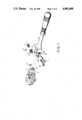
- FIG. 1 is an exploded view of an adjustable angle ratchet wrench in accordance with the present invention
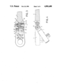
- FIG. 2 is a cross-sectional top view of the wrench of FIG. 1 in which all gears are in the normal or engaged mode;
- FIG. 3 is a cross-sectional top view of FIG. 1 in which the button is depressed and the gear is released from engagement with the handle;
- FIG. 4 is a cross-sectional side view of the wrench of FIG. 1 illustrating the rotation of the handle with respect to the ratchet wrench head;
- FIG. 5 is a cross-sectional side view of an embodiment of the prior art.
- a rectangular protrusion 11 is extended.
- the distal end of the protrusion 11 is shaped in a semi-cylindrical fashion and is toothed to form a segment teeth 12.
- the width of the protrusion 11 and segment teeth 12 is such that they fit within a Y-shaped opening formed by the tines 21 of the fork in the handle 2.
- the tines 21 are rectangular in shape and at the distal end of each are semi-cylindrical in shape about an axis between the tines 21.
- the tines 21 are bored with a cylindrical bore 210.
- the bore 21 consists of a threaded section within one tine of the fork and a stepped cylindrical opening in the other.
- the outer diameter of the stepped cylindrical opening is larger to accommodate the head of a bolt 211, and the small diameter corresponds to the diameter of the bolt 211 and the threaded section engaging with the threaded section of the bolt 211.
- the segment teeth 12 of the ratchet wrench head 1 is bored with a centrally cylindrical opening corresponding to the size of the bolt 211.
- the protrusion 11 and the first gear 12 of the ratchet wrench head 1 engage with the tines 21 of the fork in the handle 2 by means of the bolt 211 passing through the bore 210.
- a C-shaped ring 13 is provided over the bolt 211 adjacent to the inside surface of the threaded tine 21 to prevent over tightening and allow for free rotation about the bolt 211.
- the opening 22 consists of a circular shape corresponding to the diameter of a head portion of a button 3 and an inner toothed section 23.
- a first section is circular and of a diameter to accommodate the spring 5 while the remainder is also circular and corresponding in size to a shaft portion of the button 3.
- the button 3 consists of the head portion followed by a and a rectangular section and then the shaft portion.
- the rectangular section of the button 3 engages with a rectangular opening of a teeth gear 4, while the subsequent portion of the shaft of the button 3 passes through a cylindrical opening and protrudes from the opposite side of the gear teeth 4.
- the gear teeth 4 consists of a set of first teeth 41 and a set of second teeth 42, the latter being smaller and of an appropriate size to engage with the inner toothed section 23 of the handle 2, while the former being of a larger diameter and toothed to engage the segment teeth 12 of the the ratchet wrench head 1.
- the button 3 is inserted to the opening 22 passing through the gear teeth 4.
- the spring 5 is placed over the shaft portion of the button 3 and seats in the larger cylindrical opening 22 on the opposite tine 21 from the button head.
- the button 3 is then secured in place by an E-ring washer 6 in an annular groove 31 of the shaft just at the edge of the first teeth 41 of the gear teeth 4.
- FIG. 2 shows the adjustable angle ratchet wrench handle 2 in the normal engaged mode while FIG. 3 shows the adjustable angle ratchet wrench handle 2 in the disengaged, moveable mode.
- the handle 2 is hinged to the ratchet wrench head 1 by means of the bolt 211.
- the segment teeth 12 of the ratchet wrench head 1 are directly engaged with the first teeth 41 of the gear teeth 4.
- the gear teeth 4 is forced such that the second teeth 42 of the gear teeth 4 engages with the tooth section 23 of the opening 22 and the side of the first teeth 41 bears against an inner wall of the tine 21.
- the gear teeth 4 is rigidly fixed with respect to the handle 2, and as such, the ratchet wrench head 1 is also rigidly fixed due to the engagement of the first teeth 41 and the teeth of the segment teeth 12.
- the button 3 is depressed and the spring 5 is compressed.
- the second teeth 42 of the gear teeth 4 disengage with the tooth section 23 of the opening 22.
- the first teeth 41 of the gear teeth 4 still remain in contact with the segment teeth 12 of the ratchet wrench head 1.
- the teeth of the two gears mesh together and the handle 2 is able to rotate about the bolt 211 to change the angle of the handle 2 with respect to the plane of the ratchet wrench head 1.
- the cross-sectional view of FIG. 4 more clearly illustrates the relationship and relative motion of the ratchet wrench head 1 to the handle 2. It should also be noted that the handle can be rotated through an arc of approximately 180 degrees.
Landscapes
- Engineering & Computer Science (AREA)
- Mechanical Engineering (AREA)
- Details Of Spanners, Wrenches, And Screw Drivers And Accessories (AREA)
Abstract
The invention relates to an adjustable angle ratchet wrench. A ratchet wrench head is provided with a toothed protrusion. The handle has a forked end to receive the protrusion and the head and handle are hinged about a bolt therethrough. Between the tines of the fork is also disposed a gear having two different size diameters. This gear is provided on the shaft of a button which is spring loaded. In the normal position the large gear engages with the teeth of the protrusion on the head and the smaller gear engages with an inwardly toothed section of one tine of the fork such that the wrench head and handle are held rigid. When the button is depressed, the smaller gear disengages from the handle and the wrench head and handle are free to rotate through an angle of approximately 180 degrees with respect to each other. When the button is released, the spring loaded returns the gear to the normal position and the handle is fixed again.
Description
The present invention relates to a ratchet wrench and in particular to an adjustable angle ratchet wrench.
Heretofore, fixed handle ratchet wrenches were developed to facilitate the easy rotation or ratcheting of nuts and bolts. Further to this, straight extensions of different lengths were developed to accommodate hard to reach places. However, at times even this improvement was inadequate for some uses. A ratchet wrench with an adjustable angle handle was then developed. A representation of such is shown in FIG. 5 (U.S. Pat. No. 4,711,145) wherein a toothed portion 72 of the ratchet head 7 engages with a spring-loaded ball 82 and is rotatable about the central axis of the toothed portion. This design could afford different angles to the handle but under load conditions this design has the tendency to easily change angle if the torque is not carefully applied parallel to the plane of the ratchet head. This, usually sudden, change in angle quite often results in injury to the user in the form of cuts, bruises, scrapes etc., and also damage to the nut or bolt that the torque is being applied to.
It is therefore a primary object of the present invention to mitigate and/or obviate the afore-mentioned drawbacks by providing an adjustable angle ratchet wrench that is easy and convenient to use.
Another object of the present invention is to provide an adjustable angle ratchet wrench that is adjustable through an angle of approximately 180 degrees.
Another object of the present invention is to provide an adjustable angle ratchet wrench that is rigidly fixable at any angle from plus 90 to minus 90 degrees with respect to the plane of the ratchet head.
To obviate the aforementioned drawbacks and improve functionality, the present invention provides a handle hinged about a first toothed gear by a second toothed gear. The second toothed gear is spring-loaded such that, in the normal position, it is engaged with teeth of the wrench head and teeth located within the handle to fix the handle in a rigid position. To disengage, a button is depressed, a spring is compressed and the set of teeth of the second gear engaging the teeth of the handle disengage to allow rotation of the handle. The present invention offers the rigidity of a fixed handle ratchet wrench while also providing the convenience of an adjustable angle handle.
Other objects and advantages of the present invention will become apparent to those skilled in the art upon reading the detailed description provided hereinbelow, with appropriate reference to the accompanying drawings.
FIG. 1 is an exploded view of an adjustable angle ratchet wrench in accordance with the present invention;
FIG. 2 is a cross-sectional top view of the wrench of FIG. 1 in which all gears are in the normal or engaged mode;
FIG. 3 is a cross-sectional top view of FIG. 1 in which the button is depressed and the gear is released from engagement with the handle;
FIG. 4 is a cross-sectional side view of the wrench of FIG. 1 illustrating the rotation of the handle with respect to the ratchet wrench head; and
FIG. 5 is a cross-sectional side view of an embodiment of the prior art.
Referring to the perspective view of FIG. 1, wherein a ratchet wrench head 1 is shown, on a side of the ratchet wrench head 1 perpendicular to the drive shaft a rectangular protrusion 11 is extended. The distal end of the protrusion 11 is shaped in a semi-cylindrical fashion and is toothed to form a segment teeth 12. The width of the protrusion 11 and segment teeth 12 is such that they fit within a Y-shaped opening formed by the tines 21 of the fork in the handle 2. The tines 21 are rectangular in shape and at the distal end of each are semi-cylindrical in shape about an axis between the tines 21. The tines 21 are bored with a cylindrical bore 210. The bore 21 consists of a threaded section within one tine of the fork and a stepped cylindrical opening in the other. The outer diameter of the stepped cylindrical opening is larger to accommodate the head of a bolt 211, and the small diameter corresponds to the diameter of the bolt 211 and the threaded section engaging with the threaded section of the bolt 211. The segment teeth 12 of the ratchet wrench head 1 is bored with a centrally cylindrical opening corresponding to the size of the bolt 211. The protrusion 11 and the first gear 12 of the ratchet wrench head 1 engage with the tines 21 of the fork in the handle 2 by means of the bolt 211 passing through the bore 210. A C-shaped ring 13 is provided over the bolt 211 adjacent to the inside surface of the threaded tine 21 to prevent over tightening and allow for free rotation about the bolt 211.
Along another axis between the tines 21 of the fork in the handle running parallel to the previously mentioned axis, there is a cylindrical opening 22. Within one tine 21 the opening 22 consists of a circular shape corresponding to the diameter of a head portion of a button 3 and an inner toothed section 23. On the other tine 21, a first section is circular and of a diameter to accommodate the spring 5 while the remainder is also circular and corresponding in size to a shaft portion of the button 3. The button 3 consists of the head portion followed by a and a rectangular section and then the shaft portion. The rectangular section of the button 3 engages with a rectangular opening of a teeth gear 4, while the subsequent portion of the shaft of the button 3 passes through a cylindrical opening and protrudes from the opposite side of the gear teeth 4. The gear teeth 4 consists of a set of first teeth 41 and a set of second teeth 42, the latter being smaller and of an appropriate size to engage with the inner toothed section 23 of the handle 2, while the former being of a larger diameter and toothed to engage the segment teeth 12 of the the ratchet wrench head 1. The button 3 is inserted to the opening 22 passing through the gear teeth 4. The spring 5 is placed over the shaft portion of the button 3 and seats in the larger cylindrical opening 22 on the opposite tine 21 from the button head. The button 3 is then secured in place by an E-ring washer 6 in an annular groove 31 of the shaft just at the edge of the first teeth 41 of the gear teeth 4.
FIG. 2 shows the adjustable angle ratchet wrench handle 2 in the normal engaged mode while FIG. 3 shows the adjustable angle ratchet wrench handle 2 in the disengaged, moveable mode. As can be seen from FIG. 2, the handle 2 is hinged to the ratchet wrench head 1 by means of the bolt 211. The segment teeth 12 of the ratchet wrench head 1 are directly engaged with the first teeth 41 of the gear teeth 4. From the tension of the spring 5, the gear teeth 4 is forced such that the second teeth 42 of the gear teeth 4 engages with the tooth section 23 of the opening 22 and the side of the first teeth 41 bears against an inner wall of the tine 21. In this position, the gear teeth 4 is rigidly fixed with respect to the handle 2, and as such, the ratchet wrench head 1 is also rigidly fixed due to the engagement of the first teeth 41 and the teeth of the segment teeth 12.
In FIG. 3, the button 3 is depressed and the spring 5 is compressed. When the button 3 is depressed, the second teeth 42 of the gear teeth 4 disengage with the tooth section 23 of the opening 22. The first teeth 41 of the gear teeth 4 still remain in contact with the segment teeth 12 of the ratchet wrench head 1. While in this mode the teeth of the two gears mesh together and the handle 2 is able to rotate about the bolt 211 to change the angle of the handle 2 with respect to the plane of the ratchet wrench head 1. The cross-sectional view of FIG. 4 more clearly illustrates the relationship and relative motion of the ratchet wrench head 1 to the handle 2. It should also be noted that the handle can be rotated through an arc of approximately 180 degrees.
While the present invention has been explained in relation to its preferred embodiment, it is to be understood that various modifications thereof will be apparent to those skilled in the art upon reading this specification. The invention disclosed herein is therefore intended to cover all such modifications as fall within the scope of the appended claims.
Claims (2)
1. An adjustable angle ratchet wrench comprising:
(a) a wrench head including a rectangular protrusion extending outwardly from a side thereof disposed perpendicular to a drive shaft, the protrusion being provided with a semi-cylindrical first gear at one end thereof and a central cylindrical passageway;
(b) a handle including a fork defined by a pair of tines forming a Y-shaped opening sized for receiving the protrusion therein, each tine being substantially rectangular in shape and terminating in an end having a semi-cylindrical shape;
(c) a first cylindrical bore extending through the tines and including a threaded section in one tine and a stepped section in the other tine, and a bolt extending through the cylindrical bore and the central cylindrical passageway of the protrusion, the bolt being disposed in threaded engagement with the threaded section;
(d) a second cylindrical bore extending through the tines and including an outer section and toothed section in one tine, and a larger diameter inner cylindrical opening and a smaller diameter outer cylindrical opening in the other tine;
(e) a second gear provided with teeth on its outer surface and including a set of larger first teeth engageable with the first gear and a set of smaller second teeth engageable with the toothed section, the second gear further including a central rectangular bore and a cylindrical passage;
(f) a button including a cylindrical head portion, a reduced diameter cylindrical section, a rectangular section and a cylindrical shaft, the rectangular section being disposed within the central rectangular bore of the second gear and the cylindrical shaft being received through the cylindrical passage of the second gear, and a spring surrounding the cylindrical shaft and seated within the inner cylindrical opening of the tine, and means for securing the button to the tines;
(g) the wrench head being hinged to the handle for pivotal movement about the bolt during engagement of the first gear and the first teeth of the second gear, the second teeth of the second gear being urged by the spring into engagement with the toothed section of the tine so that the second gear may be disposed in rigid engagement with the handle and secure the wrench head in a rigid fixed position with respect to the handle; and
(h) whereby when the button is depressed against the spring, the smaller second teeth of the second gear is released from engagement with the toothed section of the tine, thereby permitting the wrench head to freely pivot with respect to the handle through an angle of approximately 180° C. about the bolt.
2. The wrench of claim 1 wherein the means for securing the button to the tines includes an annular groove formed in the cylindrical shaft adjacent the second gear, and a ring washer disposed in the annular groove.
Priority Applications (1)
| Application Number | Priority Date | Filing Date | Title |
|---|---|---|---|
| US07/315,565 US4901608A (en) | 1989-02-27 | 1989-02-27 | Adjustable angle ratchet wrench |
Applications Claiming Priority (1)
| Application Number | Priority Date | Filing Date | Title |
|---|---|---|---|
| US07/315,565 US4901608A (en) | 1989-02-27 | 1989-02-27 | Adjustable angle ratchet wrench |
Publications (1)
| Publication Number | Publication Date |
|---|---|
| US4901608A true US4901608A (en) | 1990-02-20 |
Family
ID=23225017
Family Applications (1)
| Application Number | Title | Priority Date | Filing Date |
|---|---|---|---|
| US07/315,565 Expired - Fee Related US4901608A (en) | 1989-02-27 | 1989-02-27 | Adjustable angle ratchet wrench |
Country Status (1)
| Country | Link |
|---|---|
| US (1) | US4901608A (en) |
Cited By (82)
| Publication number | Priority date | Publication date | Assignee | Title |
|---|---|---|---|---|
| US5526723A (en) * | 1992-08-05 | 1996-06-18 | Mutli Ct Ab | Striking tool |
| EP0768937A4 (en) * | 1994-06-16 | 1997-08-27 | James E Cole | Indexable wrenches |
| US5768960A (en) * | 1995-12-11 | 1998-06-23 | Archuleta; Tarue David | Locking swivel head ratchet wrench |
| US5784934A (en) * | 1997-01-30 | 1998-07-28 | Shinano Pneumatic Industries, Inc. | Ratchet wrench with pivotable head |
| US5794496A (en) * | 1996-12-05 | 1998-08-18 | Hand Tool Design Corporation | Pawl module for ratchet wrench |
| US5820288A (en) * | 1997-04-24 | 1998-10-13 | Splined Tools Corporation | Adjustable tool with a locking hinge mechanism |
| GB2324751A (en) * | 1997-04-28 | 1998-11-04 | James Gerald Nolan | Swing over drive for a spanner |
| US6000299A (en) * | 1997-06-16 | 1999-12-14 | Splined Tools Corporation | Modular tool system |
| US6000302A (en) * | 1998-04-07 | 1999-12-14 | Chiang; Der Ching | Tool having rotatable driving head |
| US6116122A (en) * | 1999-06-10 | 2000-09-12 | Lien-Sheng; Chen | Ratchet tool |
| US6148698A (en) * | 2000-03-07 | 2000-11-21 | Hsieh; Chih-Ching | Angle-adjustable box end wrench |
| US6161982A (en) * | 1998-04-22 | 2000-12-19 | Splined Tools Corporation | Assembly with a sealed coupler |
| US6186034B1 (en) | 1998-12-11 | 2001-02-13 | Dan E. Lamons | Flex handle adjustable wrench |
| US6220125B1 (en) * | 1999-11-29 | 2001-04-24 | Lai Lee Yu Lan | Device for adjusting angle of ratchet wrench |
| US6295898B1 (en) * | 2000-04-11 | 2001-10-02 | Chih-Ching Hsieh | Angle-adjustable wrench |
| US6311583B1 (en) | 2000-04-13 | 2001-11-06 | S. P. Air Kabusiki Kaisha | Ratchet wrench with pivotable head |
| US6405621B1 (en) | 1998-03-13 | 2002-06-18 | Snap-On Tools Company | Ratchet wrench with multi-position ratchet head |
| US6520053B2 (en) | 2001-07-20 | 2003-02-18 | Youn Chyuan Liao | Rotatable tool handle having a solid locking structure |
| US6729209B1 (en) | 2002-12-04 | 2004-05-04 | Chia Yu Chen | Rotatable tool driving head having spring lock device |
| US20040103765A1 (en) * | 2002-12-02 | 2004-06-03 | Tsung-Chieh Chang | Spanner head orientation positioning device |
| US20040144218A1 (en) * | 2003-01-28 | 2004-07-29 | Bobby Hu | Adjustable head for a wrench |
| US20040237729A1 (en) * | 2003-05-30 | 2004-12-02 | Berman Charles N. | Adjustable closed-end wrench |
| US6840141B2 (en) | 2003-01-09 | 2005-01-11 | Brian T. Cole | Radial indexing head tool with floating splined pin |
| US20050051004A1 (en) * | 2003-09-04 | 2005-03-10 | Chen Chia Yu | Tool having rotatable driving head |
| US6895839B1 (en) * | 2004-08-04 | 2005-05-24 | Chih-Ching Hsien | Control mechanism for controlling head of a box end wrench |
| US20050120836A1 (en) * | 2003-03-04 | 2005-06-09 | Anderson Steven P. | Hinged socket wrench speed handle |
| US20050178249A1 (en) * | 2003-01-09 | 2005-08-18 | Cole Charles A. | Radial indexing head tool with floating splined pin |
| US20050199102A1 (en) * | 2004-03-09 | 2005-09-15 | Chin-Ching Hsien | Socket wrench for ratchet wheel sockets |
| US20060074428A1 (en) * | 2004-10-06 | 2006-04-06 | Ralph James D | Adjustable angle pawl handle for surgical instruments |
| US20060074429A1 (en) * | 2004-10-06 | 2006-04-06 | Ralph James D | Adjustable angle handle for surgical instruments |
| US7174815B1 (en) * | 2006-05-03 | 2007-02-13 | Chih-Ching Hsieh | Hand tool with a swinging structure |
| US7197966B1 (en) * | 2006-05-26 | 2007-04-03 | Chih-Ching Hsieh | Device for pivoting and positioning head of hand tool |
| US7197965B1 (en) * | 2002-02-25 | 2007-04-03 | Anderson Steven P | Hinged socket wrench speed handle |
| US20070084310A1 (en) * | 2005-10-14 | 2007-04-19 | Sp Air Kabushiki Kaisha | Air ratchet tool with rotatable head |
| US20070141967A1 (en) * | 2005-10-14 | 2007-06-21 | Sp Air Kabushiki Kaisha | Die Grinder with Rotatable Head |
| US20070169590A1 (en) * | 2006-01-24 | 2007-07-26 | Charles Cole | Indexable, lockable pivoting mechanism for hand tool |
| US20070204727A1 (en) * | 2006-03-01 | 2007-09-06 | Pei Yang Lee | Locking flex-head ratchet wrench |
| US20070289413A1 (en) * | 2006-06-15 | 2007-12-20 | Stucky Andrew C | Swiveling driver |
| US20080022814A1 (en) * | 2006-07-31 | 2008-01-31 | Mu-Pei Chiang | Wrench |
| US20080141833A1 (en) * | 2006-12-15 | 2008-06-19 | Shen Jui-Chi | Ratchet wrench with rotatable head |
| DE102005043915B4 (en) * | 2004-09-30 | 2008-07-03 | Bobby Hu | wrench |
| US20090007733A1 (en) * | 2007-07-05 | 2009-01-08 | Ibt Holding, Llc | Clamping and cutting apparatus with adjustable head |
| USD585254S1 (en) * | 2005-11-08 | 2009-01-27 | Bsi. A/S | Turnbuckle |
| CN100479999C (en) * | 2006-03-22 | 2009-04-22 | 谢智庆 | Hand tool with swing structure |
| US20090111319A1 (en) * | 2007-10-24 | 2009-04-30 | Amphenol Corporation | Strain relief backshell assembly |
| US20100019214A1 (en) * | 2008-07-21 | 2010-01-28 | Indexable Tools, LLC | Hammer and crowbar with adjustable claw |
| US20100107828A1 (en) * | 2008-11-03 | 2010-05-06 | Juan Huerta | Adjustable Handle System for Fastening Tools That Drive Threaded Fasteners |
| US20110017024A1 (en) * | 2009-11-12 | 2011-01-27 | Meridian International Co., Ltd. | Rotary ratchet wrench |
| USD636651S1 (en) | 2010-08-17 | 2011-04-26 | Meridian International Co., Ltd. | Socket for a socket wrench |
| USD642881S1 (en) | 2010-05-28 | 2011-08-09 | Meridian International Co., Ltd. | Socket wrench |
| US20120006169A1 (en) * | 2005-11-22 | 2012-01-12 | Robert Bosch Tool Corporation | Hinge connections and power miter saw with hinge linkage linear guide including such hinge connections |
| CN103042515A (en) * | 2011-10-14 | 2013-04-17 | 无锡沃骐医疗科技有限公司 | Rotation handle convenient to disassemble |
| TWI397455B (en) * | 2011-07-21 | 2013-06-01 | ||
| US8459151B2 (en) | 2010-05-28 | 2013-06-11 | Meridian International Co., Ltd. | Ratcheting socket wrench and sockets |
| CN103659705A (en) * | 2012-09-07 | 2014-03-26 | 陳怡富 | Tool meshing device |
| US20140090523A1 (en) * | 2012-09-28 | 2014-04-03 | Kabo Tool Company | Angle adjusting structure of ratchet wrench |
| US8857303B2 (en) | 2005-11-22 | 2014-10-14 | Robert Bosch Gmbh | Locking mechanism for miter saw with hinge linkage linear guide |
| US8881631B2 (en) | 2011-07-29 | 2014-11-11 | Robert Bosch Gmbh | Glide movement controller and power miter saw including such controller |
| US9079296B1 (en) | 2013-04-23 | 2015-07-14 | Anthony Martucci | Swiveling ratchet |
| US9079297B2 (en) | 2011-04-15 | 2015-07-14 | Apex Brands, Inc. | Flex-head wrench |
| US9114509B2 (en) | 2012-02-14 | 2015-08-25 | Meridian International Co., Ltd. | Rotary ratcheting wrench |
| US9221157B1 (en) * | 2014-07-29 | 2015-12-29 | Yung Fong Tools Co., Ltd. | Angle controlling device for a wrench |
| US20160303666A1 (en) * | 2015-04-17 | 2016-10-20 | Robert Bosch Tool Corporation | Miter Saw Having an Angled Glide Hinge |
| US20170190029A1 (en) * | 2016-01-04 | 2017-07-06 | Julio Cuesta | Ratcheting flex-wrench system |
| US20170210000A1 (en) * | 2016-01-24 | 2017-07-27 | Chih-Ming Lee | Hand tool |
| DE102014109027B4 (en) * | 2014-06-26 | 2017-12-21 | Yi-Fu Chen | Ratchet with an angle adjustment mechanism |
| DE202018001908U1 (en) | 2018-03-28 | 2018-08-30 | Dirk Bechmann | Angular flexible ratchet extension |
| US20190375090A1 (en) * | 2018-06-06 | 2019-12-12 | Yi-Min Li | Joint for a swing wrench |
| US20220274233A1 (en) * | 2021-02-26 | 2022-09-01 | De Poan Pneumatic Corp. | Pneumatic hand tool with adjustable operating angle |
| USD972382S1 (en) * | 2020-12-15 | 2022-12-13 | Cheng-Yu Li | Dual head socket wrench |
| USD1002309S1 (en) | 2020-12-30 | 2023-10-24 | Milwaukee Electric Tool Corporation | Wrench |
| US11986927B2 (en) | 2020-12-28 | 2024-05-21 | Milwaukee Electric Tool Corporation | Tool with pivoting portion and locking mechanism |
| USD1039351S1 (en) * | 2021-06-04 | 2024-08-20 | Apex Brands, Inc. | Ratchet wrench |
| US20240399543A1 (en) * | 2023-06-01 | 2024-12-05 | Neng-Chia Shih | Multi-angle ratchet wrench |
| USD1062409S1 (en) * | 2022-09-30 | 2025-02-18 | Jianjun Han | Wrench |
| USD1072591S1 (en) * | 2023-05-25 | 2025-04-29 | Hong Ann Tool Industries Co., Ltd. | Ratchet wrench |
| USD1075448S1 (en) * | 2023-12-06 | 2025-05-20 | Ming Shin Tools Co., Ltd. | Ratchet wrench |
| USD1081300S1 (en) * | 2023-05-25 | 2025-07-01 | Hong Ann Tool Industries Co., Ltd. | Wrench joint |
| USD1088777S1 (en) * | 2023-04-27 | 2025-08-19 | Harbor Freight Tools Usa, Inc. | Ratchet |
| USD1090210S1 (en) * | 2023-04-27 | 2025-08-26 | Harbor Freight Tools Usa, Inc. | Ratchet |
| USD1090212S1 (en) * | 2023-12-07 | 2025-08-26 | Vego Garden Inc. | Wrench |
| US12451645B2 (en) | 2022-12-08 | 2025-10-21 | Amphenol Interconnect India Pvt. Ltd. | Backshell adapter assembly |
Citations (5)
| Publication number | Priority date | Publication date | Assignee | Title |
|---|---|---|---|---|
| US763745A (en) * | 1903-10-14 | 1904-06-28 | John M Ostrum | Compound tool. |
| US2518139A (en) * | 1946-03-06 | 1950-08-08 | Standard Pressed Steel Co | Magazine tool |
| US2921773A (en) * | 1958-03-19 | 1960-01-19 | Hoelzer Bruce | Craftsman's adjustable pry bar |
| DE3023882A1 (en) * | 1980-06-26 | 1982-01-14 | Hazet-Werk Hermann Zerver Gmbh & Co Kg, 5630 Remscheid | Variable position box spanner-operating handle - has splined connecting piece working together with rotary spring loaded coupling element |
| US4794829A (en) * | 1982-03-06 | 1989-01-03 | Hans Mesenhoeller | Ratchet-type wrench |
-
1989
- 1989-02-27 US US07/315,565 patent/US4901608A/en not_active Expired - Fee Related
Patent Citations (5)
| Publication number | Priority date | Publication date | Assignee | Title |
|---|---|---|---|---|
| US763745A (en) * | 1903-10-14 | 1904-06-28 | John M Ostrum | Compound tool. |
| US2518139A (en) * | 1946-03-06 | 1950-08-08 | Standard Pressed Steel Co | Magazine tool |
| US2921773A (en) * | 1958-03-19 | 1960-01-19 | Hoelzer Bruce | Craftsman's adjustable pry bar |
| DE3023882A1 (en) * | 1980-06-26 | 1982-01-14 | Hazet-Werk Hermann Zerver Gmbh & Co Kg, 5630 Remscheid | Variable position box spanner-operating handle - has splined connecting piece working together with rotary spring loaded coupling element |
| US4794829A (en) * | 1982-03-06 | 1989-01-03 | Hans Mesenhoeller | Ratchet-type wrench |
Cited By (117)
| Publication number | Priority date | Publication date | Assignee | Title |
|---|---|---|---|---|
| US5526723A (en) * | 1992-08-05 | 1996-06-18 | Mutli Ct Ab | Striking tool |
| EP0768937A4 (en) * | 1994-06-16 | 1997-08-27 | James E Cole | Indexable wrenches |
| US5768960A (en) * | 1995-12-11 | 1998-06-23 | Archuleta; Tarue David | Locking swivel head ratchet wrench |
| US5794496A (en) * | 1996-12-05 | 1998-08-18 | Hand Tool Design Corporation | Pawl module for ratchet wrench |
| US5784934A (en) * | 1997-01-30 | 1998-07-28 | Shinano Pneumatic Industries, Inc. | Ratchet wrench with pivotable head |
| US5820288A (en) * | 1997-04-24 | 1998-10-13 | Splined Tools Corporation | Adjustable tool with a locking hinge mechanism |
| GB2324751A (en) * | 1997-04-28 | 1998-11-04 | James Gerald Nolan | Swing over drive for a spanner |
| US6000299A (en) * | 1997-06-16 | 1999-12-14 | Splined Tools Corporation | Modular tool system |
| US6405621B1 (en) | 1998-03-13 | 2002-06-18 | Snap-On Tools Company | Ratchet wrench with multi-position ratchet head |
| US6000302A (en) * | 1998-04-07 | 1999-12-14 | Chiang; Der Ching | Tool having rotatable driving head |
| US6161982A (en) * | 1998-04-22 | 2000-12-19 | Splined Tools Corporation | Assembly with a sealed coupler |
| US6186034B1 (en) | 1998-12-11 | 2001-02-13 | Dan E. Lamons | Flex handle adjustable wrench |
| US6116122A (en) * | 1999-06-10 | 2000-09-12 | Lien-Sheng; Chen | Ratchet tool |
| US6220125B1 (en) * | 1999-11-29 | 2001-04-24 | Lai Lee Yu Lan | Device for adjusting angle of ratchet wrench |
| US6148698A (en) * | 2000-03-07 | 2000-11-21 | Hsieh; Chih-Ching | Angle-adjustable box end wrench |
| US6295898B1 (en) * | 2000-04-11 | 2001-10-02 | Chih-Ching Hsieh | Angle-adjustable wrench |
| US6311583B1 (en) | 2000-04-13 | 2001-11-06 | S. P. Air Kabusiki Kaisha | Ratchet wrench with pivotable head |
| US6520053B2 (en) | 2001-07-20 | 2003-02-18 | Youn Chyuan Liao | Rotatable tool handle having a solid locking structure |
| US7197965B1 (en) * | 2002-02-25 | 2007-04-03 | Anderson Steven P | Hinged socket wrench speed handle |
| US6745650B1 (en) * | 2002-12-02 | 2004-06-08 | Tsung-Chieh Chang | Spanner head orientation positioning device |
| US20040103765A1 (en) * | 2002-12-02 | 2004-06-03 | Tsung-Chieh Chang | Spanner head orientation positioning device |
| US6729209B1 (en) | 2002-12-04 | 2004-05-04 | Chia Yu Chen | Rotatable tool driving head having spring lock device |
| US6840141B2 (en) | 2003-01-09 | 2005-01-11 | Brian T. Cole | Radial indexing head tool with floating splined pin |
| US7156003B2 (en) | 2003-01-09 | 2007-01-02 | Cole Charles A | Radial indexing head tool with floating splined pin |
| US20050178249A1 (en) * | 2003-01-09 | 2005-08-18 | Cole Charles A. | Radial indexing head tool with floating splined pin |
| US20040144218A1 (en) * | 2003-01-28 | 2004-07-29 | Bobby Hu | Adjustable head for a wrench |
| US7171875B2 (en) * | 2003-01-28 | 2007-02-06 | Bobby Hu | Adjustable head for a wrench |
| US20050120836A1 (en) * | 2003-03-04 | 2005-06-09 | Anderson Steven P. | Hinged socket wrench speed handle |
| US20040237729A1 (en) * | 2003-05-30 | 2004-12-02 | Berman Charles N. | Adjustable closed-end wrench |
| US7017456B2 (en) * | 2003-05-30 | 2006-03-28 | Berman Charles N | Adjustable closed-end wrench |
| US20050051004A1 (en) * | 2003-09-04 | 2005-03-10 | Chen Chia Yu | Tool having rotatable driving head |
| US6871569B1 (en) | 2003-09-04 | 2005-03-29 | Chia Yu Chen | Tool having rotatable driving head |
| US20050199102A1 (en) * | 2004-03-09 | 2005-09-15 | Chin-Ching Hsien | Socket wrench for ratchet wheel sockets |
| US7055409B2 (en) * | 2004-03-09 | 2006-06-06 | Chin-Ching Hsien | Socket wrench for ratchet wheel sockets |
| US6895839B1 (en) * | 2004-08-04 | 2005-05-24 | Chih-Ching Hsien | Control mechanism for controlling head of a box end wrench |
| DE102005043915B4 (en) * | 2004-09-30 | 2008-07-03 | Bobby Hu | wrench |
| US20060074429A1 (en) * | 2004-10-06 | 2006-04-06 | Ralph James D | Adjustable angle handle for surgical instruments |
| US20060074428A1 (en) * | 2004-10-06 | 2006-04-06 | Ralph James D | Adjustable angle pawl handle for surgical instruments |
| US7922719B2 (en) | 2004-10-06 | 2011-04-12 | Biodynamics, Llc | Adjustable angle pawl handle for surgical instruments |
| US8480453B2 (en) | 2005-10-14 | 2013-07-09 | Sp Air Kabushiki Kaisha | Die grinder with rotatable head |
| US20070084310A1 (en) * | 2005-10-14 | 2007-04-19 | Sp Air Kabushiki Kaisha | Air ratchet tool with rotatable head |
| US20070141967A1 (en) * | 2005-10-14 | 2007-06-21 | Sp Air Kabushiki Kaisha | Die Grinder with Rotatable Head |
| USD585254S1 (en) * | 2005-11-08 | 2009-01-27 | Bsi. A/S | Turnbuckle |
| US8752461B2 (en) * | 2005-11-22 | 2014-06-17 | Robert Bosch Gmbh | Hinge connections and power miter saw with hinge linkage linear guide including such hinge connections |
| US20120006169A1 (en) * | 2005-11-22 | 2012-01-12 | Robert Bosch Tool Corporation | Hinge connections and power miter saw with hinge linkage linear guide including such hinge connections |
| US8857303B2 (en) | 2005-11-22 | 2014-10-14 | Robert Bosch Gmbh | Locking mechanism for miter saw with hinge linkage linear guide |
| US7682099B2 (en) * | 2006-01-24 | 2010-03-23 | Cole Charles A | Indexable, lockable pivoting mechanism for hand tool |
| US20070169590A1 (en) * | 2006-01-24 | 2007-07-26 | Charles Cole | Indexable, lockable pivoting mechanism for hand tool |
| US7318366B2 (en) * | 2006-03-01 | 2008-01-15 | Easco Hand Tools, Inc. | Locking flex-head ratchet wrench |
| US8028607B2 (en) * | 2006-03-01 | 2011-10-04 | Easco Hand Tools, Inc. | Locking flex-head ratchet wrench |
| US20070266830A1 (en) * | 2006-03-01 | 2007-11-22 | Easco Hand Tools, Inc. | Locking Flex-Head Ratchet Wrench |
| US20070204727A1 (en) * | 2006-03-01 | 2007-09-06 | Pei Yang Lee | Locking flex-head ratchet wrench |
| US8474350B2 (en) | 2006-03-01 | 2013-07-02 | Easco Hand Tools, Inc. | Locking flex-head ratchet wrench |
| US8695459B2 (en) | 2006-03-01 | 2014-04-15 | Apex Brands, Inc. | Locking flex-head ratchet wrench |
| CN100479999C (en) * | 2006-03-22 | 2009-04-22 | 谢智庆 | Hand tool with swing structure |
| US7174815B1 (en) * | 2006-05-03 | 2007-02-13 | Chih-Ching Hsieh | Hand tool with a swinging structure |
| US7197966B1 (en) * | 2006-05-26 | 2007-04-03 | Chih-Ching Hsieh | Device for pivoting and positioning head of hand tool |
| US20070289413A1 (en) * | 2006-06-15 | 2007-12-20 | Stucky Andrew C | Swiveling driver |
| US7497148B2 (en) | 2006-06-15 | 2009-03-03 | Stucky Andrew C | Swiveling driver |
| US7424839B2 (en) * | 2006-07-31 | 2008-09-16 | Mu-Pei Chiang | Wrench |
| US20080022814A1 (en) * | 2006-07-31 | 2008-01-31 | Mu-Pei Chiang | Wrench |
| US20080141833A1 (en) * | 2006-12-15 | 2008-06-19 | Shen Jui-Chi | Ratchet wrench with rotatable head |
| US7735399B2 (en) | 2007-07-05 | 2010-06-15 | IBT Holdings, Inc | Clamping and cutting apparatus with adjustable head |
| US20090007733A1 (en) * | 2007-07-05 | 2009-01-08 | Ibt Holding, Llc | Clamping and cutting apparatus with adjustable head |
| US7837495B2 (en) | 2007-10-24 | 2010-11-23 | Amphenol Corporation | Strain relief backshell assembly |
| US20090111319A1 (en) * | 2007-10-24 | 2009-04-30 | Amphenol Corporation | Strain relief backshell assembly |
| WO2009055681A3 (en) * | 2007-10-24 | 2009-09-17 | Amphenol Corporation | Strain relief backshell assembly |
| US20100019214A1 (en) * | 2008-07-21 | 2010-01-28 | Indexable Tools, LLC | Hammer and crowbar with adjustable claw |
| US8424845B2 (en) | 2008-07-21 | 2013-04-23 | Indexable Tools, LLC | Hammer and crowbar with adjustable claw |
| US20100107828A1 (en) * | 2008-11-03 | 2010-05-06 | Juan Huerta | Adjustable Handle System for Fastening Tools That Drive Threaded Fasteners |
| US8069753B2 (en) | 2009-11-12 | 2011-12-06 | Meridian International Co., Ltd. | Rotary ratchet wrench |
| USD657216S1 (en) | 2009-11-12 | 2012-04-10 | Meridan International Co., Ltd. | Rotary ratchet wrench |
| USD632535S1 (en) | 2009-11-12 | 2011-02-15 | Meridian International Co., Ltd. | Rotary ratchet wrench |
| USD657215S1 (en) | 2009-11-12 | 2012-04-10 | Meridian International Co., Ltd. | Rotary ratchet wrench |
| US20110017024A1 (en) * | 2009-11-12 | 2011-01-27 | Meridian International Co., Ltd. | Rotary ratchet wrench |
| USD636648S1 (en) | 2009-11-12 | 2011-04-26 | Meridian International Co., Ltd. | Rotary ratchet wrench |
| US8794110B2 (en) | 2009-11-12 | 2014-08-05 | Meridian International Co., Ltd. | Rotary ratchet wrench |
| USD640518S1 (en) | 2009-11-12 | 2011-06-28 | Meridian International Co., Ltd. | Rotary ratchet wrench |
| US8459151B2 (en) | 2010-05-28 | 2013-06-11 | Meridian International Co., Ltd. | Ratcheting socket wrench and sockets |
| USD642881S1 (en) | 2010-05-28 | 2011-08-09 | Meridian International Co., Ltd. | Socket wrench |
| USD636651S1 (en) | 2010-08-17 | 2011-04-26 | Meridian International Co., Ltd. | Socket for a socket wrench |
| US9079297B2 (en) | 2011-04-15 | 2015-07-14 | Apex Brands, Inc. | Flex-head wrench |
| TWI397455B (en) * | 2011-07-21 | 2013-06-01 | ||
| US8881631B2 (en) | 2011-07-29 | 2014-11-11 | Robert Bosch Gmbh | Glide movement controller and power miter saw including such controller |
| CN103042515A (en) * | 2011-10-14 | 2013-04-17 | 无锡沃骐医疗科技有限公司 | Rotation handle convenient to disassemble |
| US9114509B2 (en) | 2012-02-14 | 2015-08-25 | Meridian International Co., Ltd. | Rotary ratcheting wrench |
| CN103659705B (en) * | 2012-09-07 | 2016-04-13 | 陳怡富 | The geared assembly of instrument |
| CN103659705A (en) * | 2012-09-07 | 2014-03-26 | 陳怡富 | Tool meshing device |
| US9132535B2 (en) * | 2012-09-28 | 2015-09-15 | Kabo Tool Company | Angle adjusting structure of ratchet wrench |
| US20140090523A1 (en) * | 2012-09-28 | 2014-04-03 | Kabo Tool Company | Angle adjusting structure of ratchet wrench |
| US9079296B1 (en) | 2013-04-23 | 2015-07-14 | Anthony Martucci | Swiveling ratchet |
| DE102014109027B4 (en) * | 2014-06-26 | 2017-12-21 | Yi-Fu Chen | Ratchet with an angle adjustment mechanism |
| US9221157B1 (en) * | 2014-07-29 | 2015-12-29 | Yung Fong Tools Co., Ltd. | Angle controlling device for a wrench |
| US20160303666A1 (en) * | 2015-04-17 | 2016-10-20 | Robert Bosch Tool Corporation | Miter Saw Having an Angled Glide Hinge |
| US10207345B2 (en) * | 2015-04-17 | 2019-02-19 | Robert Bosch Tool Corporation | Miter saw having an angled glide hinge |
| US20170190029A1 (en) * | 2016-01-04 | 2017-07-06 | Julio Cuesta | Ratcheting flex-wrench system |
| US20170210000A1 (en) * | 2016-01-24 | 2017-07-27 | Chih-Ming Lee | Hand tool |
| US10226861B2 (en) * | 2016-01-24 | 2019-03-12 | Chih-Ming Lee | Hand tool |
| DE202018001908U1 (en) | 2018-03-28 | 2018-08-30 | Dirk Bechmann | Angular flexible ratchet extension |
| DE102018002586A1 (en) | 2018-03-28 | 2019-10-02 | Dirk Bechmann | Angular flexible ratchet extension |
| US20190375090A1 (en) * | 2018-06-06 | 2019-12-12 | Yi-Min Li | Joint for a swing wrench |
| USD972382S1 (en) * | 2020-12-15 | 2022-12-13 | Cheng-Yu Li | Dual head socket wrench |
| US11986927B2 (en) | 2020-12-28 | 2024-05-21 | Milwaukee Electric Tool Corporation | Tool with pivoting portion and locking mechanism |
| USD1002309S1 (en) | 2020-12-30 | 2023-10-24 | Milwaukee Electric Tool Corporation | Wrench |
| USD1079419S1 (en) | 2020-12-30 | 2025-06-17 | Milwaukee Electric Tool Corporation | Wrench |
| US20220274233A1 (en) * | 2021-02-26 | 2022-09-01 | De Poan Pneumatic Corp. | Pneumatic hand tool with adjustable operating angle |
| US11801588B2 (en) * | 2021-02-26 | 2023-10-31 | De Poan Pneumatic Corp. | Pneumatic hand tool with adjustable operating angle |
| USD1039351S1 (en) * | 2021-06-04 | 2024-08-20 | Apex Brands, Inc. | Ratchet wrench |
| USD1062409S1 (en) * | 2022-09-30 | 2025-02-18 | Jianjun Han | Wrench |
| US12451645B2 (en) | 2022-12-08 | 2025-10-21 | Amphenol Interconnect India Pvt. Ltd. | Backshell adapter assembly |
| USD1090210S1 (en) * | 2023-04-27 | 2025-08-26 | Harbor Freight Tools Usa, Inc. | Ratchet |
| USD1088777S1 (en) * | 2023-04-27 | 2025-08-19 | Harbor Freight Tools Usa, Inc. | Ratchet |
| USD1072591S1 (en) * | 2023-05-25 | 2025-04-29 | Hong Ann Tool Industries Co., Ltd. | Ratchet wrench |
| USD1081300S1 (en) * | 2023-05-25 | 2025-07-01 | Hong Ann Tool Industries Co., Ltd. | Wrench joint |
| US20240399543A1 (en) * | 2023-06-01 | 2024-12-05 | Neng-Chia Shih | Multi-angle ratchet wrench |
| USD1075448S1 (en) * | 2023-12-06 | 2025-05-20 | Ming Shin Tools Co., Ltd. | Ratchet wrench |
| USD1090212S1 (en) * | 2023-12-07 | 2025-08-26 | Vego Garden Inc. | Wrench |
Similar Documents
| Publication | Publication Date | Title |
|---|---|---|
| US4901608A (en) | Adjustable angle ratchet wrench | |
| US5857390A (en) | Reversible ratchet wrench including thin-walled sockets | |
| US5495783A (en) | Reversible ratchet wrench with direction indicia | |
| US5964129A (en) | Ratchet wrench with a direction control ratchet member | |
| US5109737A (en) | Extended tool | |
| US8813611B2 (en) | Strap wrench | |
| US5630343A (en) | Power drive multiple socket wrench | |
| US4532832A (en) | Dual-mode ratchet wrench | |
| US3972252A (en) | Top turn ratchet | |
| US20150314425A1 (en) | Ratchet wrench with handgrip ratchet control | |
| US4407175A (en) | Tool for rotating threaded fasteners | |
| US5140875A (en) | Socket wrench | |
| US5095782A (en) | Open-ended adjustable ratchet wrench | |
| US5746099A (en) | Adjustable open-wrench with a sliding side jaw having a releasable adjustment mechanism to allow ratcheting operation | |
| US5377566A (en) | Adjustable ratchet wrench apparatus | |
| US4318314A (en) | Ratchet wrench assembly | |
| US4099430A (en) | Rewind ratchet wrench | |
| US6739222B2 (en) | Ratchet socket | |
| WO1993024280A1 (en) | Continuous drive ratchet tool | |
| US5251519A (en) | T-handle wrench kit | |
| US4944765A (en) | Prosthetic drive device for rotatable tool | |
| US7997168B2 (en) | Adjustable ratchet wrench | |
| US4546677A (en) | Slip-on screwdriver ratchet | |
| US4781083A (en) | Ratchet key chuck tool | |
| US6880432B2 (en) | Ratchet socket |
Legal Events
| Date | Code | Title | Description |
|---|---|---|---|
| FEPP | Fee payment procedure |
Free format text: PAYOR NUMBER ASSIGNED (ORIGINAL EVENT CODE: ASPN); ENTITY STATUS OF PATENT OWNER: SMALL ENTITY |
|
| FPAY | Fee payment |
Year of fee payment: 4 |
|
| REMI | Maintenance fee reminder mailed | ||
| LAPS | Lapse for failure to pay maintenance fees | ||
| FP | Lapsed due to failure to pay maintenance fee |
Effective date: 19980225 |
|
| STCH | Information on status: patent discontinuation |
Free format text: PATENT EXPIRED DUE TO NONPAYMENT OF MAINTENANCE FEES UNDER 37 CFR 1.362 |