US4901585A - Method and apparatus for roll nip load measurement - Google Patents
Method and apparatus for roll nip load measurement Download PDFInfo
- Publication number
- US4901585A US4901585A US07/277,967 US27796788A US4901585A US 4901585 A US4901585 A US 4901585A US 27796788 A US27796788 A US 27796788A US 4901585 A US4901585 A US 4901585A
- Authority
- US
- United States
- Prior art keywords
- load
- plates
- parallel
- plate
- edges
- Prior art date
- Legal status (The legal status is an assumption and is not a legal conclusion. Google has not performed a legal analysis and makes no representation as to the accuracy of the status listed.)
- Expired - Fee Related
Links
- 238000000034 method Methods 0.000 title abstract description 9
- 238000005259 measurement Methods 0.000 title description 2
- 238000006073 displacement reaction Methods 0.000 abstract description 3
- 239000012530 fluid Substances 0.000 description 4
- 239000011888 foil Substances 0.000 description 2
- 238000010276 construction Methods 0.000 description 1
- 238000012937 correction Methods 0.000 description 1
- 238000004049 embossing Methods 0.000 description 1
- 239000000463 material Substances 0.000 description 1
- 230000013011 mating Effects 0.000 description 1
- 238000005476 soldering Methods 0.000 description 1
- 239000013598 vector Substances 0.000 description 1
Images

Classifications
-
- G—PHYSICS
- G01—MEASURING; TESTING
- G01L—MEASURING FORCE, STRESS, TORQUE, WORK, MECHANICAL POWER, MECHANICAL EFFICIENCY, OR FLUID PRESSURE
- G01L5/00—Apparatus for, or methods of, measuring force, work, mechanical power, or torque, specially adapted for specific purposes
- G01L5/0061—Force sensors associated with industrial machines or actuators
- G01L5/0076—Force sensors associated with manufacturing machines
- G01L5/0085—Force sensors adapted for insertion between cooperating machine elements, e.g. for measuring the nip force between rollers
-
- B—PERFORMING OPERATIONS; TRANSPORTING
- B21—MECHANICAL METAL-WORKING WITHOUT ESSENTIALLY REMOVING MATERIAL; PUNCHING METAL
- B21B—ROLLING OF METAL
- B21B38/00—Methods or devices for measuring, detecting or monitoring specially adapted for metal-rolling mills, e.g. position detection, inspection of the product
- B21B38/08—Methods or devices for measuring, detecting or monitoring specially adapted for metal-rolling mills, e.g. position detection, inspection of the product for measuring roll-force
Definitions
- the present invention generally relates to compressive force measurement. More particularly, the invention provides a method and apparatus for measuring the nip loading force applied compressively between two process rolls.
- an object of the present invention to provide a method and apparatus capable of measuring maximum process nip loads within one inch of a closed nip position.
- Another object of the invention is to provide a test load cell having an extremely low sectional profile.
- a strain gauge load cell that comprises two matched ramp plates. Both plates are provided with low ramp angle rails along opposite edges. The four rail edges are given a hard, polished finish to minimize their mating friction coefficient.
- normally applied loads cause a lateral displacement of the two plates. Between the rail pairs, the plates are held together, in opposition to the lateral displacement, by a connective load strip. Such opposition load forces stress the load strip in tension.
- a strain gauge bonded to the load strip serves to sense the magnitude of such tension. Friction losses and ramp angle resolution corrections are accommodated by electrical calibration to provide a direct report of the normally applied nip load.
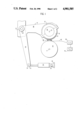
- FIG. 1 is an elevational schematic of the invention in an operating environment
- FIG. 2 is an exploded assembly of the invention
- FIG. 3 is an operating assembly of the invention.
- FIG. 4 is a sectional view of the invention taken from the cutting plane IV--IV of FIG. 3.
- FIG. 1 schematically illustrates a representative mounting arrangement for a pair of high pressure nip rolls such as found in a papermachine wet-press section or on a web or foil embossing machine.
- the lower roll 10 rotates about a fixed position axis 11 while the upper roll 12 rotates about a movable axis 13.
- Axle stubs 14 projecting from opposite ends of roll 12 are carried by a journal assembly having a base 15 and cap 16.
- the journal base 15 is an integral element of or rigidly secured to the short arm 18 of a bellcrank 17.
- a journal 20 is provided to pivot the bellcrank 17 about the axis of a frame mounted axle 21.
- the rod eye 23 of a loading strut 22 is secured by a frame mounted pivot pin 24.
- a second pivot pin 25 secures the cylinder end of load strut 22 to the machine frame 26.
- Fluid pressure within the strut 22 cylinder acts upon the rod to torque the bellcrank 17 about the axle 21.
- Such bellcrank torque loads the upper roll 12 against the lower roll 10.
- the present invention load cell 30 is placed in the nip between the two rolls. More than one such load cell may be distributed along the roll length.
- FIGS. 2, 3 and 4 illustrate the load cell 30 construction as comprising a pair of ramp plates 31 and 32.
- Each ramp plate includes along respective lateral edges, a pair of tapered rails 33 having hard, smooth, straight edge surfaces 34 at a low plane angle, 5° for example, relative to the exterior plate faces 35 and 36.
- the length of said rails 33 is less than the length dimension of the plates 31 between heel and toe end edges 44 and 45, respectively, to provide a notch space 37 which accommodates a key block 38 and the thickness of load plate 39.
- Load plate 39 has a width dimension to pass without interference between the inside surfaces of rails 33. Length of the load plate 39 is determined by the length of ramp plates 31 and 32. At each terminal end of the load plate 39 a kerfed spine 40 is secured by means of soldering or swaging. At the center of the load plate, a strain gauge 41 is bonded. Electrical leads 42 from the strain gauge are routed through an aperature 43 in one of the rails 33 to a balance circuit and amplifier 44 (FIG. 1). Responsive signals from the amplifier 44 are reported by analog meter 45 or by digital means not shown. Simple calibration will correlate the meter 45 needle position with a corresponding nip load in pounds or kilograms.
- the two ramp plates 31 and 32 When assembled and normally loaded as shown by the force vectors F in FIG. 3, the two ramp plates 31 and 32 will thrust tensile load on the load plate 39. Such tensile load on the plate 39 results in a proportional change in the strain gauge electrical characteristic which is reported by the meter 45.
- Representative dimensions for a load cell 30 as described may include a 14 cm length, a 15 cm width and a 2.25 cm height.
- the rail surfaces are preferably polished to a 4 micron finish. Thickness of the load plate 39 is determined by the maximum load to be imposed and the associated strain gauge 41.
Abstract
Disclosed is a method and apparatus for directly measuring the radially applied, compressive nip load between two press rolls. Matched, low angle ramp plates are connected tensilely by a load strip which supports a strain gauge. The assembly, having less than one inch of nip section thickness, is placed in the subject roll nip and loaded normally. Due to the ramp angle base, the two plates are displaced in opposite directions normal to the radial load. The connective load strip opposes the opposite displacement thereby stressing the strain gauge.
Description
1. Field of the Invention
The present invention generally relates to compressive force measurement. More particularly, the invention provides a method and apparatus for measuring the nip loading force applied compressively between two process rolls.
2. Description of the Prior Art
Numerous web handling processes such as papermaking utilize compressive nip forces as are obtained from two oppositely loaded rolls. When the process requires extremely high nip loads, the rolls are mounted on massive bell cranks or other mechanical means for multiplying the force of hydraulic or pneumatic loading struts.
These mechanical force multiplying devices operate as matched pairs with each assembly of the pair supporting a respective roll axis end. When these mechanical load multipliers are correctly aligned, the fluid pressure applied to the loading struts is directly proportional to the radial nip load. However, slight misalignment or journal wear may cause large resulting nip load differences: notwithstanding identical fluid pressure applied to the respective loading struts. Consequently, it is occasionally necessary to directly measure the load asserted within such a roll nip to verify or calibrate the normal fluid pressure system.
When such test loading is done, it is essential that the subject roll nip be as close to the normal operating position as possible since small relative angle differences between the several links in the force multiplying mechanism result in large resulting load differences. For this reason, process roll nips respective to extremely thin materials such as paper or foil represent a unique difficulty.
It is therefore, an object of the present invention to provide a method and apparatus capable of measuring maximum process nip loads within one inch of a closed nip position.
Another object of the invention is to provide a test load cell having an extremely low sectional profile.
These and other objects of the invention, as will be apparent from the following description, are accomplished by means of a strain gauge load cell that comprises two matched ramp plates. Both plates are provided with low ramp angle rails along opposite edges. The four rail edges are given a hard, polished finish to minimize their mating friction coefficient. When the ramp plates are assembled with rail edge-to-edge contact, normally applied loads cause a lateral displacement of the two plates. Between the rail pairs, the plates are held together, in opposition to the lateral displacement, by a connective load strip. Such opposition load forces stress the load strip in tension. A strain gauge bonded to the load strip serves to sense the magnitude of such tension. Friction losses and ramp angle resolution corrections are accommodated by electrical calibration to provide a direct report of the normally applied nip load.
Relative to the drawing wherein like reference characters designate like or similar elements throughout the several figures of the drawing:
FIG. 1 is an elevational schematic of the invention in an operating environment;
FIG. 2 is an exploded assembly of the invention;
FIG. 3 is an operating assembly of the invention; and,
FIG. 4 is a sectional view of the invention taken from the cutting plane IV--IV of FIG. 3.
FIG. 1 schematically illustrates a representative mounting arrangement for a pair of high pressure nip rolls such as found in a papermachine wet-press section or on a web or foil embossing machine. Here, the lower roll 10 rotates about a fixed position axis 11 while the upper roll 12 rotates about a movable axis 13. Axle stubs 14 projecting from opposite ends of roll 12 are carried by a journal assembly having a base 15 and cap 16. The journal base 15 is an integral element of or rigidly secured to the short arm 18 of a bellcrank 17. At the elbow formed by the juncture of the bellcrank short arm 18 and long arm 19, a journal 20 is provided to pivot the bellcrank 17 about the axis of a frame mounted axle 21.
Near the distal end of the bellcrank long arm 19, the rod eye 23 of a loading strut 22 is secured by a frame mounted pivot pin 24. A second pivot pin 25 secures the cylinder end of load strut 22 to the machine frame 26. Fluid pressure within the strut 22 cylinder acts upon the rod to torque the bellcrank 17 about the axle 21. Such bellcrank torque loads the upper roll 12 against the lower roll 10. To quantitatively measure that load, the present invention load cell 30 is placed in the nip between the two rolls. More than one such load cell may be distributed along the roll length.
FIGS. 2, 3 and 4 illustrate the load cell 30 construction as comprising a pair of ramp plates 31 and 32. Each ramp plate includes along respective lateral edges, a pair of tapered rails 33 having hard, smooth, straight edge surfaces 34 at a low plane angle, 5° for example, relative to the exterior plate faces 35 and 36. The length of said rails 33 is less than the length dimension of the plates 31 between heel and toe end edges 44 and 45, respectively, to provide a notch space 37 which accommodates a key block 38 and the thickness of load plate 39.
Load plate 39 has a width dimension to pass without interference between the inside surfaces of rails 33. Length of the load plate 39 is determined by the length of ramp plates 31 and 32. At each terminal end of the load plate 39 a kerfed spine 40 is secured by means of soldering or swaging. At the center of the load plate, a strain gauge 41 is bonded. Electrical leads 42 from the strain gauge are routed through an aperature 43 in one of the rails 33 to a balance circuit and amplifier 44 (FIG. 1). Responsive signals from the amplifier 44 are reported by analog meter 45 or by digital means not shown. Simple calibration will correlate the meter 45 needle position with a corresponding nip load in pounds or kilograms.
When assembled and normally loaded as shown by the force vectors F in FIG. 3, the two ramp plates 31 and 32 will thrust tensile load on the load plate 39. Such tensile load on the plate 39 results in a proportional change in the strain gauge electrical characteristic which is reported by the meter 45.
Representative dimensions for a load cell 30 as described may include a 14 cm length, a 15 cm width and a 2.25 cm height. The rail surfaces are preferably polished to a 4 micron finish. Thickness of the load plate 39 is determined by the maximum load to be imposed and the associated strain gauge 41.
Having fully described our invention,
Claims (2)
1. A low profile load cell comprising a pair of parallel plane plates, each having a pair of lateral edges, a toe edge and a heel edge, said plates being separated by respective pairs of laterally spaced, parallel rails secured along the lateral edges of each of the respective plates, said rails having load bearing edges in a plane set at a small angle to the plate planes, load plate means spanning the length of said parallel plates between said rails and between oppositely directed ones of the heel edges, opposite ends of said load plate means being temporarily secured to said heel edges against tensile stress imposed on said load plate means between said opposite ends and strain sensing means secured to said load plate means to measure the magnitude of said tensile stress resulting from a compressive load imposed upon and substantially normal to said parallel plane plates.
2. A load cell as described by claim 1 wherein said load plate ends are secured to spine elements which confine said load plate ends against said heel edges and key block means positioned between the heel edge of one parallel plate and the toe edge of the other parallel plate.
Priority Applications (2)
| Application Number | Priority Date | Filing Date | Title |
|---|---|---|---|
| US07/277,967 US4901585A (en) | 1988-11-30 | 1988-11-30 | Method and apparatus for roll nip load measurement |
| US07/432,015 US4945772A (en) | 1988-11-30 | 1989-11-06 | Method of roll nip load measurement |
Applications Claiming Priority (1)
| Application Number | Priority Date | Filing Date | Title |
|---|---|---|---|
| US07/277,967 US4901585A (en) | 1988-11-30 | 1988-11-30 | Method and apparatus for roll nip load measurement |
Related Child Applications (1)
| Application Number | Title | Priority Date | Filing Date |
|---|---|---|---|
| US07/432,015 Division US4945772A (en) | 1988-11-30 | 1989-11-06 | Method of roll nip load measurement |
Publications (1)
| Publication Number | Publication Date |
|---|---|
| US4901585A true US4901585A (en) | 1990-02-20 |
Family
ID=23063132
Family Applications (1)
| Application Number | Title | Priority Date | Filing Date |
|---|---|---|---|
| US07/277,967 Expired - Fee Related US4901585A (en) | 1988-11-30 | 1988-11-30 | Method and apparatus for roll nip load measurement |
Country Status (1)
| Country | Link |
|---|---|
| US (1) | US4901585A (en) |
Cited By (5)
| Publication number | Priority date | Publication date | Assignee | Title |
|---|---|---|---|---|
| US4974442A (en) * | 1989-04-26 | 1990-12-04 | Westinghouse Electric Corp. | Method and apparatus for calibrating rolling mill on-line load measuring equipment |
| US5079942A (en) * | 1989-04-26 | 1992-01-14 | Westinghouse Electric Corp. | Method and apparatus for calibrating rolling mill on-line load measuring equipment |
| US20040079147A1 (en) * | 2001-02-22 | 2004-04-29 | Maeenpaeae Tapio | Measurement method and system in the manufacture of paper or paperboard |
| US20070033976A1 (en) * | 2003-03-07 | 2007-02-15 | Usinor | Device and method for calibrating a planishing roller device by means of an instrumented bar |
| CN103257006A (en) * | 2013-05-31 | 2013-08-21 | 罗炳军 | PCB laminator idler wheel pressure testing instrument |
Citations (15)
| Publication number | Priority date | Publication date | Assignee | Title |
|---|---|---|---|---|
| DE551472C (en) * | 1929-11-07 | 1932-06-01 | Dunlop Rubber Co | Device for measuring or comparing the elongation and tensile strength of webs made of vegetable fiber fabrics or other stretchable materials, especially threads |
| US2612934A (en) * | 1949-06-13 | 1952-10-07 | Paul P M Dubosclard | Forming roll machine |
| US3383591A (en) * | 1964-10-14 | 1968-05-14 | United States Steel Corp | Method and apparatus for indicating wear on rolls by combining signals proportional to rolling force and speed |
| US3555895A (en) * | 1968-06-21 | 1971-01-19 | J E Doyle Co The | Roll setting combination and method |
| US3796094A (en) * | 1972-09-25 | 1974-03-12 | Eastman Kodak Co | Method and apparatus for continuously detecting abnormal cross-sectional areas in running tow |
| US3803908A (en) * | 1971-03-27 | 1974-04-16 | Mitsubishi Heavy Ind Ltd | Material discriminating device for metallic plates |
| US4016756A (en) * | 1972-06-08 | 1977-04-12 | Beloit Corporation | Nip load sensing device |
| US4033183A (en) * | 1976-10-08 | 1977-07-05 | Bethlehem Steel Corporation | Horizontal- and vertical-roll force measuring system |
| GB1487396A (en) * | 1975-07-15 | 1977-09-28 | Davy Loewy Ltd | Tensiometers |
| SU669209A1 (en) * | 1977-08-04 | 1979-06-25 | Ивановский научно-исследовательский институт хлопчатобумажной промышленности | Device for measuring the load of weight rollers of drafting devices of textile machines |
| US4175430A (en) * | 1977-04-04 | 1979-11-27 | Utah Development Company | Load measuring apparatus |
| SU885832A1 (en) * | 1977-08-05 | 1981-11-30 | Центральный Ордена Трудового Красного Знамени Научно-Исследовательский Автомобильный И Автомоторный Институт Нами | Device for measuring forces |
| GB2104670A (en) * | 1981-08-18 | 1983-03-09 | Mettler Instrumente Ag | Force measuring devices |
| US4466297A (en) * | 1982-04-01 | 1984-08-21 | Pfister Gmbh | Device for measuring a force |
| JPS60183534A (en) * | 1984-02-29 | 1985-09-19 | Mitsubishi Petrochem Co Ltd | Measuring method of roller pressure |
-
1988
- 1988-11-30 US US07/277,967 patent/US4901585A/en not_active Expired - Fee Related
Patent Citations (15)
| Publication number | Priority date | Publication date | Assignee | Title |
|---|---|---|---|---|
| DE551472C (en) * | 1929-11-07 | 1932-06-01 | Dunlop Rubber Co | Device for measuring or comparing the elongation and tensile strength of webs made of vegetable fiber fabrics or other stretchable materials, especially threads |
| US2612934A (en) * | 1949-06-13 | 1952-10-07 | Paul P M Dubosclard | Forming roll machine |
| US3383591A (en) * | 1964-10-14 | 1968-05-14 | United States Steel Corp | Method and apparatus for indicating wear on rolls by combining signals proportional to rolling force and speed |
| US3555895A (en) * | 1968-06-21 | 1971-01-19 | J E Doyle Co The | Roll setting combination and method |
| US3803908A (en) * | 1971-03-27 | 1974-04-16 | Mitsubishi Heavy Ind Ltd | Material discriminating device for metallic plates |
| US4016756A (en) * | 1972-06-08 | 1977-04-12 | Beloit Corporation | Nip load sensing device |
| US3796094A (en) * | 1972-09-25 | 1974-03-12 | Eastman Kodak Co | Method and apparatus for continuously detecting abnormal cross-sectional areas in running tow |
| GB1487396A (en) * | 1975-07-15 | 1977-09-28 | Davy Loewy Ltd | Tensiometers |
| US4033183A (en) * | 1976-10-08 | 1977-07-05 | Bethlehem Steel Corporation | Horizontal- and vertical-roll force measuring system |
| US4175430A (en) * | 1977-04-04 | 1979-11-27 | Utah Development Company | Load measuring apparatus |
| SU669209A1 (en) * | 1977-08-04 | 1979-06-25 | Ивановский научно-исследовательский институт хлопчатобумажной промышленности | Device for measuring the load of weight rollers of drafting devices of textile machines |
| SU885832A1 (en) * | 1977-08-05 | 1981-11-30 | Центральный Ордена Трудового Красного Знамени Научно-Исследовательский Автомобильный И Автомоторный Институт Нами | Device for measuring forces |
| GB2104670A (en) * | 1981-08-18 | 1983-03-09 | Mettler Instrumente Ag | Force measuring devices |
| US4466297A (en) * | 1982-04-01 | 1984-08-21 | Pfister Gmbh | Device for measuring a force |
| JPS60183534A (en) * | 1984-02-29 | 1985-09-19 | Mitsubishi Petrochem Co Ltd | Measuring method of roller pressure |
Cited By (7)
| Publication number | Priority date | Publication date | Assignee | Title |
|---|---|---|---|---|
| US4974442A (en) * | 1989-04-26 | 1990-12-04 | Westinghouse Electric Corp. | Method and apparatus for calibrating rolling mill on-line load measuring equipment |
| US5079942A (en) * | 1989-04-26 | 1992-01-14 | Westinghouse Electric Corp. | Method and apparatus for calibrating rolling mill on-line load measuring equipment |
| US20040079147A1 (en) * | 2001-02-22 | 2004-04-29 | Maeenpaeae Tapio | Measurement method and system in the manufacture of paper or paperboard |
| US6910376B2 (en) | 2001-02-22 | 2005-06-28 | Metso Paper, Inc. | Measurement method and system in the manufacture of paper or paperboard |
| US20070033976A1 (en) * | 2003-03-07 | 2007-02-15 | Usinor | Device and method for calibrating a planishing roller device by means of an instrumented bar |
| US7584638B2 (en) * | 2003-03-07 | 2009-09-08 | Usinor | Device and method for calibrating a planishing roller device by means of an instrumented bar |
| CN103257006A (en) * | 2013-05-31 | 2013-08-21 | 罗炳军 | PCB laminator idler wheel pressure testing instrument |
Similar Documents
| Publication | Publication Date | Title |
|---|---|---|
| US3376537A (en) | Shear strain load cell | |
| US4112751A (en) | Arrangement for measuring a radial force applied to a bearing | |
| US4866984A (en) | Sensor and system for continuous determination of paper strength | |
| CA1115985A (en) | Load cell | |
| JPH0235079B2 (en) | ||
| CA1210260A (en) | Rolling mill | |
| US5925832A (en) | Torsional sensing load cell | |
| US5804738A (en) | Method and apparatus for on-line testing of the stiffness or strength of panels and especially of wood panels | |
| US5777240A (en) | Load cell and load cell beam assembly | |
| US4215754A (en) | Load measuring system for leaf spring suspensions | |
| US3824846A (en) | Holder for force transducer | |
| WO2000039542A1 (en) | Load measurement | |
| US4945772A (en) | Method of roll nip load measurement | |
| US4561512A (en) | Load cell scale of unitized construction | |
| CA1307408C (en) | Web tension transducer | |
| US6898989B2 (en) | Load cell | |
| US4901585A (en) | Method and apparatus for roll nip load measurement | |
| JPS5923889B2 (en) | How to measure the thrust load of a roll in a rolling mill | |
| US3713333A (en) | Force measuring apparatus | |
| US4312241A (en) | Load cell | |
| GB2320332A (en) | Apparatus for the uniaxial investigation of microtensile samples | |
| CA1038663A (en) | Controlled deflection rolls | |
| US4744429A (en) | Load measurement | |
| WO1996017233A1 (en) | A method and a device for two-shaft force measurement and its application to the determination of tensile force and varying deflection angle in a continuous web | |
| US4798134A (en) | Pressure compensated single nip three-roll press |
Legal Events
| Date | Code | Title | Description |
|---|---|---|---|
| AS | Assignment |
Owner name: WESTVACO CORPORATION, A CORP. OF DE, NEW YORK Free format text: ASSIGNMENT OF ASSIGNORS INTEREST.;ASSIGNORS:SHEPARD, MICHAEL L.;SNYDER, CHARLES A. II;REEL/FRAME:005001/0683 Effective date: 19881128 |
|
| FPAY | Fee payment |
Year of fee payment: 4 |
|
| REMI | Maintenance fee reminder mailed | ||
| LAPS | Lapse for failure to pay maintenance fees | ||
| FP | Lapsed due to failure to pay maintenance fee |
Effective date: 19980225 |
|
| STCH | Information on status: patent discontinuation |
Free format text: PATENT EXPIRED DUE TO NONPAYMENT OF MAINTENANCE FEES UNDER 37 CFR 1.362 |