US4901579A - Stray magnetic field control system for vibration testing apparatus - Google Patents
Stray magnetic field control system for vibration testing apparatus Download PDFInfo
- Publication number
- US4901579A US4901579A US07/269,783 US26978388A US4901579A US 4901579 A US4901579 A US 4901579A US 26978388 A US26978388 A US 26978388A US 4901579 A US4901579 A US 4901579A
- Authority
- US
- United States
- Prior art keywords
- magnetic field
- stray magnetic
- control system
- stray
- output
- Prior art date
- Legal status (The legal status is an assumption and is not a legal conclusion. Google has not performed a legal analysis and makes no representation as to the accuracy of the status listed.)
- Expired - Fee Related
Links
- 238000012360 testing method Methods 0.000 title claims description 32
- 230000005355 Hall effect Effects 0.000 claims abstract description 11
- 230000004907 flux Effects 0.000 claims abstract description 11
- 230000008859 change Effects 0.000 description 4
- 230000002411 adverse Effects 0.000 description 3
- 238000010586 diagram Methods 0.000 description 3
- 230000007704 transition Effects 0.000 description 3
- 238000006243 chemical reaction Methods 0.000 description 2
- 230000000694 effects Effects 0.000 description 2
- 229920006395 saturated elastomer Polymers 0.000 description 2
- 238000012546 transfer Methods 0.000 description 2
- 238000004804 winding Methods 0.000 description 2
- CWYNVVGOOAEACU-UHFFFAOYSA-N Fe2+ Chemical compound [Fe+2] CWYNVVGOOAEACU-UHFFFAOYSA-N 0.000 description 1
- XUIMIQQOPSSXEZ-UHFFFAOYSA-N Silicon Chemical compound [Si] XUIMIQQOPSSXEZ-UHFFFAOYSA-N 0.000 description 1
- 230000009471 action Effects 0.000 description 1
- 239000003990 capacitor Substances 0.000 description 1
- 230000003111 delayed effect Effects 0.000 description 1
- 230000001627 detrimental effect Effects 0.000 description 1
- 230000005672 electromagnetic field Effects 0.000 description 1
- 238000007429 general method Methods 0.000 description 1
- 239000000463 material Substances 0.000 description 1
- 230000035945 sensitivity Effects 0.000 description 1
- 229910052710 silicon Inorganic materials 0.000 description 1
- 239000010703 silicon Substances 0.000 description 1
Images
Classifications
-
- G—PHYSICS
- G01—MEASURING; TESTING
- G01M—TESTING STATIC OR DYNAMIC BALANCE OF MACHINES OR STRUCTURES; TESTING OF STRUCTURES OR APPARATUS, NOT OTHERWISE PROVIDED FOR
- G01M7/00—Vibration-testing of structures; Shock-testing of structures
- G01M7/02—Vibration-testing by means of a shake table
- G01M7/022—Vibration control arrangements, e.g. for generating random vibrations
Definitions
- This invention relates to vibration testing systems and more particularly to a control system for minimizing the stray magnetic field in the test environment of vibration testing systems of the type which employ direct current magnetic fields to produce the vibration energy. Vibration testing systems are often referred to for convenience as “shakers,” or “shake tables.”
- shakers are used to mechanically shake an item for the purpose of diagnostically testing responses to certain driving forces.
- the item is physically attached to a moving portion of the shaker and when the shaker is activated, the item is subjected to a variety of test conditions.
- the moving portion of the shaker is typically driven by a force which may be continuous, cyclical or impulsed.
- One class of these shakers employs the use of an electromagnetic field between field and armature windings. Various driving signals are impressed across the armature winding to control the movement of the shaker.
- Vibration testing systems are employed to test the effects of vibration on various types of equipment and component parts.
- vibration test systems which employ direct current magnetic fields to produce the required vibration energy
- high magnitude flux densities are produced.
- These high magnetic flux densities are also present in the test environment area of the vibration testing system which adversely affects the equipment or part being tested.
- vibration testing systems are usually provided with a suitable degaussing coil.
- the degaussing coil is positioned between the vibration testing system structure and the table thereof upon which the specimen to be tested is mounted. The degaussing coil operates by generating a magnetic field in opposition to the field produced by the vibration testing system which tends to cancel the undesired field.
- the level of the stray magnetic field is still high enough to adversely affect the equipment or part being tested.
- the magnetic field produced by the magnetic structure (body) of the vibration testing system is due to saturation of the body's field. This saturated field creates a leakage flux that is not proportional to the field supply voltage.
- the degaussing coil (not saturated), however, produces a field which is proportional to the supply current. Accordingly, as the supply voltage varies with line voltage, and the coil resistance varies with coil temperature, there is a residual stray field which can be detrimental to a desirable test environment.
- the stray magnetic flux caused by the magnetic structure of the vibration testing systems is monitored and controlled by the control system of this invention.
- the stray magnetic field control system of the present invention comprises a degauss coil, a Hall-Effect magnetic field sensor utilized to measure the stray magnetic field at a position near the area where the speciment to be tested is mounted, an amplifier/low pass filter means connected to the output of the sensor to amplify and remove noise from such output, an analog to digital converter connected to the output of the amplifier/filter, and a phase controlled degauss coil power supply for controlling the current supplied to the degauss coil.
- the output of the Hall-Effect sensor is suitably utilized to control the output of the phase controlled power supply such that the current supplied to the degauss coil is controlled in a manner to correct (minimize) the stray magnetic field.
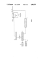
- FIG. 1 is a block diagram of a system for controlling the stray magnetic field in accordance with this invention.
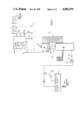
- FIG. 2 is a schematic circuit diagram of one embodiment of the stray magnetic field control system of the present invention.
- the control system includes a means 12 for sensing the stray magnetic field in the test specimen mounting area of a vibration testing system or shaker 10.
- means 12 is a Hall effect sensor device suitably mounted and positioned to sense the stray magnetic field.
- the Hall effect sensor device produces a voltage which is proportional to the surrounding stray magnetic field.
- the very low voltage output of the Hall effect sensor device 12 is amplified and has noise removed by a suitable amplifier/filter means 14.
- the output of amplifier/filter means 14 is proportional to the magnitude of the stray magnetic field sensed by means 12.
- amplifier/filter means 14 takes a very small signal, on the order of a few millivolts per gauss, and amplifies it into a signal that would have a range of 0 to +5 volts for a range of about 60 gauss.
- amplifier/filter means 14 is a straight voltage amplifier that converts the low voltage signal from the Hall effect sensor 12 to a signal in the range of 4 to 5 volts in preparation for application to an analog to digital converter.
- the amplified and cleaned up (filtered) signal proportional to the stray magnetic field from amplifier/filter means 14, is applied to an analog to digital (A/D) converter 16.
- the analog signal from amplifier/filter means 14 is converted in A/D converter 16 to a digital number, which number now represents the strength of the stray magnetic field.
- the system also includes a suitable computer means 18.
- Computer means 18 can be a generic microprocessor. In the particular arrangement illustrated and described in FIG. 2, an 8-bit, single chip microprocessor is used.
- the microprocessor 18 has the various algorithms, system time constants, control characteristics and the like maintained within the microprocessors internal ROM. During operation the control loop works to provide timely and precise control of the stray magnetic field.
- the microprocessor 18 controls the operation of the control system as well as controlling access to the look-up table and making decisions about what to do with the information, and furnishing the correct information to the phase controlled power supply to control the current to the degauss coil.
- Microprocessor 18 takes the digital number supplied to it from A/D converter 16 and compares it with a reference number, illustrated by the block 20.
- the reference number represents the desired strength of the stray magnetic field surrounding the Hall effect sensor device 12.
- the microprocessor 18 goes to a look-up table 22 which tells the microprocessor how to react to this deviation or "error."
- the reference number block 20 and look-up table block 22 are shown as individual blocks but would usually be provided as programmed firmware or in RAM as software.
- Microprocessor 18 takes the information from the look-up table and provides a control signal to the phase controlled power supply 24.
- the power supply 24 is responsive to this control signal from microprocessor 18 and the output thereof is controlled accordingly to either increase or decrease the current supplied to the degauss coil 25, to correct (minimize) the stray magnetic field.
- FIG. 2 shows a detailed schematic circuit diagram of one embodiment of the control system of ths invention.
- the Hall effect magnetic field sensor 12 is positioned to measure the stray magnetic field generated by the shaker 10 at a position near the area where the specimen to be tested is mounted.
- sensor 12 should be distanced from ferrous materials, electrical coils, or other magnetic field influences to optimize system performance.
- the output of the sensor 12 is a voltage ofset from its 0 Gaussian voltage of approximately 6.0 volts.
- the sensor requires a stable 12.0 VDC supply. To this end, a separate voltage regulator and power supply (not shown) may be provided.
- the output sensitivity of the sensor 12 is approximately 1.5 mV/Gauss and varies over or under the nominal 6 volts zero Gaussian voltage depending on stray flux polarities.
- the voltage from sensor 12 is amplified and filtered by the amplifier/low pass filter means 14 formed by operational amplifier 32, capacitors 34, 25, 36, and 37 and resistors 38, 39, and 40.
- Potentiometer 50 is connected to ground through resistor 51 and operates through resistor 52 to provide the offset adjustment for the sensor 12.
- the voltage at terminal point 54 should be approximately 2.5 volts when the system is operational and the stray field conditions are as desired. A voltage above 2.5 volts at terminal point 54 indicates that too much current is flowing to the degauss coil 25 and a voltage below 2.5 volts indicates that too little current is flowing.
- the reference for the stray flux control voltage is internally set to a digital value of 128 which corresponds to an input analog voltage of approximately 2.5 volts.
- the output from the amplifier 32 is connected to analog to digital converter 16 which in turn is connected to microprocessor 18 in conventional manner through a parallel interface.
- the A/D converter 16 is connected with the microprocessor 18 via a conventional data path, generally designated at 17, and control path, generally designated at 19.
- the data path 17 comprises the eight leads which provide the 8 data bits to the 8-bit microprocessor 18.
- the control path 19 comprises four control leads: the CLK (clock) lead, the WR (write) lead over which the microprocessor tells the A/D converter to commence a conversion, the RD (read) lead over which the microprocessor is told to read the information, and the INT (interrupt) lead over which the microprocessor is told that the conversion is complete.
- phase control employing a conventional phase controlled power supply 24.
- Appropriate trigger signals are provided to phase controlled power supply 24 to control the output thereof to either increase or decrease the current supplied degauss coil 25 to correct (minimize) the stray magnetic field. This is simply accomplished by phase control in well known manner. That is, by controlling the phase relationship between the gate trigger signal and the A-C supply voltage, the percentage of the "on" time in each cycle can be controlled to thereby control the current supplied to degauss coil 25.
- Power supply 24 may employ a silicon controlled rectifier (SCR), a bi-directional SCR (Triac), or other suitable control element.
- the internal power supply is arranged to supply 12 volts for the System use and also to supply zero crossing phase information to the Z terminal of microprocessor 18 in the form of a square wave with transition to below 1.0 volts and above 2.5 volts at every zero crossing of the 115 volts AC supply line. The direction of these transitions is unimportant but must occur with the power line zero crossings.
- a longer or shorter trigger delay is calculated by the microprocessor 18 if there is a deviation from the internal reference 20, which can be programmed in as firmware or in RAM as software.
- the actual delayed trigger pulse is initiated by lowering the voltage on the microprocessor T terminal which is buffered and inverted by resistor 55 and transistor 56 for application to the phase controlled power supply 24.
- the output is a transition to 5 VDC after the appropriate delay.
- the trigger pulse occurs once for each half cycle of the 115 VAC line and the effective control delay range of the microprocessor is from approximately 100 microseconds after zero crossing to 6.5 milliseconds after the zero crossing.
- the system of the present invention functions as an infinite gain, dead band control system. That is, any error in stray flux outside of the dead band will result in a change in the delay time of the supply trigger pulse to the phase controlled power supply 24. Even the smallest offset outside of the dead band will ultimately assert the full control range of the control system if the aforementioned change does not correct the error condition. If large errors are measured, then the delay will change rapidly and will continue more slowly as the error is reduced.
- the control range of the control system is approximately 65% to 95% of the field supply voltage. This corresponds to a stray field control range of approximately 40 gauss total.
Landscapes
- Physics & Mathematics (AREA)
- General Physics & Mathematics (AREA)
- Measuring Magnetic Variables (AREA)
Abstract
Description
Claims (7)
Priority Applications (1)
| Application Number | Priority Date | Filing Date | Title |
|---|---|---|---|
| US07/269,783 US4901579A (en) | 1987-05-29 | 1988-11-10 | Stray magnetic field control system for vibration testing apparatus |
Applications Claiming Priority (2)
| Application Number | Priority Date | Filing Date | Title |
|---|---|---|---|
| US5565087A | 1987-05-29 | 1987-05-29 | |
| US07/269,783 US4901579A (en) | 1987-05-29 | 1988-11-10 | Stray magnetic field control system for vibration testing apparatus |
Related Parent Applications (1)
| Application Number | Title | Priority Date | Filing Date |
|---|---|---|---|
| US5565087A Continuation-In-Part | 1987-05-29 | 1987-05-29 |
Publications (1)
| Publication Number | Publication Date |
|---|---|
| US4901579A true US4901579A (en) | 1990-02-20 |
Family
ID=26734482
Family Applications (1)
| Application Number | Title | Priority Date | Filing Date |
|---|---|---|---|
| US07/269,783 Expired - Fee Related US4901579A (en) | 1987-05-29 | 1988-11-10 | Stray magnetic field control system for vibration testing apparatus |
Country Status (1)
| Country | Link |
|---|---|
| US (1) | US4901579A (en) |
Cited By (4)
| Publication number | Priority date | Publication date | Assignee | Title |
|---|---|---|---|---|
| US7119691B2 (en) * | 2003-10-17 | 2006-10-10 | Sensormatic Electronics Corporation | Electronic article surveillance marker deactivator using phase control deactivation |
| WO2009023501A1 (en) * | 2007-08-15 | 2009-02-19 | The Boeing Company | Pyrotechnic shock simulation system and method |
| CN105225791A (en) * | 2015-10-30 | 2016-01-06 | 北京自动化控制设备研究所 | A kind of overall degaussing gear of magnetic screen bucket |
| CN111649893A (en) * | 2020-06-30 | 2020-09-11 | 苏州苏试试验集团股份有限公司 | Spatial three-axis magnetic field control method for electric vibration table |
Citations (3)
| Publication number | Priority date | Publication date | Assignee | Title |
|---|---|---|---|---|
| US3062041A (en) * | 1960-05-13 | 1962-11-06 | Walter G Spodnewski | Degaussing plate assembly for electromagnetic vibration exciter |
| US3482163A (en) * | 1967-05-24 | 1969-12-02 | Tektronix Inc | Magnetic signal measuring device including degaussing means |
| US4402032A (en) * | 1981-03-12 | 1983-08-30 | Cone-Blanchard Machine Company | Electromagnet power supply and demagnetizer |
-
1988
- 1988-11-10 US US07/269,783 patent/US4901579A/en not_active Expired - Fee Related
Patent Citations (3)
| Publication number | Priority date | Publication date | Assignee | Title |
|---|---|---|---|---|
| US3062041A (en) * | 1960-05-13 | 1962-11-06 | Walter G Spodnewski | Degaussing plate assembly for electromagnetic vibration exciter |
| US3482163A (en) * | 1967-05-24 | 1969-12-02 | Tektronix Inc | Magnetic signal measuring device including degaussing means |
| US4402032A (en) * | 1981-03-12 | 1983-08-30 | Cone-Blanchard Machine Company | Electromagnet power supply and demagnetizer |
Cited By (5)
| Publication number | Priority date | Publication date | Assignee | Title |
|---|---|---|---|---|
| US7119691B2 (en) * | 2003-10-17 | 2006-10-10 | Sensormatic Electronics Corporation | Electronic article surveillance marker deactivator using phase control deactivation |
| WO2009023501A1 (en) * | 2007-08-15 | 2009-02-19 | The Boeing Company | Pyrotechnic shock simulation system and method |
| US8306796B2 (en) | 2007-08-15 | 2012-11-06 | The Boeing Company | Pyrotechnic shock simulation system and method |
| CN105225791A (en) * | 2015-10-30 | 2016-01-06 | 北京自动化控制设备研究所 | A kind of overall degaussing gear of magnetic screen bucket |
| CN111649893A (en) * | 2020-06-30 | 2020-09-11 | 苏州苏试试验集团股份有限公司 | Spatial three-axis magnetic field control method for electric vibration table |
Similar Documents
| Publication | Publication Date | Title |
|---|---|---|
| US5442290A (en) | MRI gradient drive current control using all digital controller | |
| US5140263A (en) | System for determining position of an internal, movable conductive element | |
| US4277751A (en) | Low-power magnetometer circuit with constant current drive | |
| US4579137A (en) | Electro-pneumatic current to pressure transducer and pneumatic and electronic control circuits therefor | |
| JPH04218817A (en) | Object movement control device | |
| US5124648A (en) | Single winding saturable core magnetometer with field nulling | |
| US5103163A (en) | Current transducer | |
| KR100460376B1 (en) | Variable gain amplifier with temperature compensation for use in a disk drive system | |
| US4585978A (en) | Magnetostrictive actuator with feedback compensation | |
| US4290018A (en) | Magnetic field strength measuring apparatus with triangular waveform drive means | |
| US4988933A (en) | Head driving circuit | |
| US4841209A (en) | Actuator control system with displacement sensor fault detection | |
| US4901579A (en) | Stray magnetic field control system for vibration testing apparatus | |
| US4866373A (en) | Superconducting current detecting circuit employing DC flux parametron circuit | |
| US4460867A (en) | Method and circuit for measuring of current | |
| JPH06313718A (en) | Position detection circuit | |
| US4300095A (en) | Self excited saturatable core magnetic field detection apparatus | |
| US3432747A (en) | Spot recording and pickup methods and apparatus for the determination of hardness of relatively moving magnetic material without contacting the same | |
| US6392375B1 (en) | Method of driving with high precision a voice coil motor and related architecture | |
| US4303886A (en) | Magnetic field strength measuring apparatus | |
| US2940747A (en) | Electric weighing and balancing system | |
| EP0202033B1 (en) | A degaussing apparatus | |
| US4463314A (en) | Earth field compensation for a magnetic detector by imparting a permanent magnetization to a magnetic material contiguous the detector | |
| US6704160B2 (en) | Feedback control system, control method, magnetic disk unit and method of controlling magnetic disk unit | |
| US4543835A (en) | Dry flow sensor with a linear force transducer |
Legal Events
| Date | Code | Title | Description |
|---|---|---|---|
| AS | Assignment |
Owner name: ELECTRONICS, INC., A CA CORP. Free format text: ASSIGNMENT OF ASSIGNORS INTEREST.;ASSIGNOR:BUTTS, GARY;REEL/FRAME:004968/0567 Effective date: 19881109 Owner name: ELECTRONICS, INC., STATELESS Free format text: ASSIGNMENT OF ASSIGNORS INTEREST;ASSIGNOR:BUTTS, GARY;REEL/FRAME:004968/0567 Effective date: 19881109 |
|
| CC | Certificate of correction | ||
| AS | Assignment |
Owner name: CHASE LINCOLN FIRST BANK, N.A., NEW YORK Free format text: SECURITY INTEREST;ASSIGNOR:LING ELECTRONICS, INC. A CA CORP.;REEL/FRAME:006169/0075 Effective date: 19920722 |
|
| FPAY | Fee payment |
Year of fee payment: 4 |
|
| REMI | Maintenance fee reminder mailed | ||
| LAPS | Lapse for failure to pay maintenance fees | ||
| FP | Lapsed due to failure to pay maintenance fee |
Effective date: 19980225 |
|
| STCH | Information on status: patent discontinuation |
Free format text: PATENT EXPIRED DUE TO NONPAYMENT OF MAINTENANCE FEES UNDER 37 CFR 1.362 |