US4901460A - Display device - Google Patents
Display device Download PDFInfo
- Publication number
- US4901460A US4901460A US07/178,146 US17814688A US4901460A US 4901460 A US4901460 A US 4901460A US 17814688 A US17814688 A US 17814688A US 4901460 A US4901460 A US 4901460A
- Authority
- US
- United States
- Prior art keywords
- suspension means
- uppermost
- roller
- electrically
- sheet
- Prior art date
- Legal status (The legal status is an assumption and is not a legal conclusion. Google has not performed a legal analysis and makes no representation as to the accuracy of the status listed.)
- Expired - Lifetime
Links
- 239000000725 suspension Substances 0.000 claims abstract description 92
- 230000007246 mechanism Effects 0.000 claims description 11
- 238000006073 displacement reaction Methods 0.000 claims description 5
- 229920003023 plastic Polymers 0.000 description 7
- 239000004033 plastic Substances 0.000 description 7
- 239000012769 display material Substances 0.000 description 3
- 230000007257 malfunction Effects 0.000 description 2
- 239000000463 material Substances 0.000 description 2
- 239000002184 metal Substances 0.000 description 2
- 230000032683 aging Effects 0.000 description 1
- 238000010276 construction Methods 0.000 description 1
- 230000000694 effects Effects 0.000 description 1
- 230000005611 electricity Effects 0.000 description 1
- 230000037431 insertion Effects 0.000 description 1
- 238000003780 insertion Methods 0.000 description 1
- 239000000126 substance Substances 0.000 description 1
Images
Classifications
-
- G—PHYSICS
- G09—EDUCATION; CRYPTOGRAPHY; DISPLAY; ADVERTISING; SEALS
- G09F—DISPLAYING; ADVERTISING; SIGNS; LABELS OR NAME-PLATES; SEALS
- G09F11/00—Indicating arrangements for variable information in which the complete information is permanently attached to a movable support which brings it to the display position
- G09F11/30—Indicating arrangements for variable information in which the complete information is permanently attached to a movable support which brings it to the display position the display elements being fed one by one from storage place to a display position
- G09F11/32—Indicating arrangements for variable information in which the complete information is permanently attached to a movable support which brings it to the display position the display elements being fed one by one from storage place to a display position the feeding means comprising belts or chains, e.g. endless belts or chains
Definitions
- This invention relates to display devices and seeks to provide an improved form of the display device which is the subject of British patent specification No. 1221442 which is equivalent to U.S. Pat. No. 3,568,345.
- Display devices or poster changing machines in accordance with what is described and illustrated in the specification of British patent No. 1221442 have now been in use for a long time and, whilst they have proved to be much more reliable and generally satisfactory than display devices that were known before the introduction of ones in accordance with patent No. 1221442, the long period of usage has disclosed certain shortcomings which the present invention avoids, or at least very significantly reduces.
- a display device for displaying a number of indicia one after the other, said device comprising a plurality of flexible sheets for supporting indicia on their opposite sides, each said sheet including suspension means at or near its uppermost and lowermost (when vertically disposed) ends, the device also comprising a roller, a ramp for receiving said sheets in a stack with the indicia at one side of an end sheet visible to a viewer of the device, means for defining a closed path around the roller for the suspension means between opposite ends of said ramp, electrically-driven means for positively engaging the uppermost suspension means of a sheet in the viewing position and for transporting that sheet around the roller, gate means which are displaceable upon engagement thereof by said uppermost suspension means, owing to the positive engagement of the uppermost suspension means by the electrically-driven means to permit movement of said uppermost suspension means out of said path, the uppermost suspension means subsequently being the leading suspension means as regards the direction of displacement around the roller, the lowermost, and subsequently trailing, suspension means of
- a device in accordance with the present invention has also been improved by introducing a "gate" to allow the chain-carried cradles to pick up only one suspension means at a time, thus preventing the suspension means from becoming "bunched” or otherwise entangled at the location at which the chain-carried cradles must essentially pick up only one suspension means if the machine is not to become jammed.
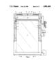
- FIG. 1 is a front elevation of an improved device in accordance with the invention with an enclosing cabinet in which the device is located being ommitted;
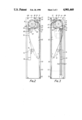
- FIG. 2 is a section taken on the line II--II in FIG. 1;
- FIG. 3 is a section taken on the line III--III in FIG. 1;
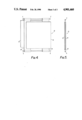
- FIG. 4 is an exploded view, in perspective, of a flexible sheet comprising and inextensible member having two transparent layers on the opposite sides thereof;
- FIG. 5 is an edge view of the sheet of FIG. 4.
- two synthetic plastics or other shaped plates 44 that extend parallel to one another and perpendicular to both the front and rear of the device are mounted towards the opposite lateral sides thereof where they will be engaged, during the use of the device, by the opposite ends of rods 4, affording suspension means, which are mounted at the alternately interchanged leading and rear ends of sheets 3 upon which the indicia to be displayed by the device is carried.
- Chains 10 carry cradles 11 which repeatedly engage successive suspension rods 4 and, as described in the specification of patent No.
- the sheets 3 move the sheets 3 from a viewing position at the front of the device to a position at the rear of a stack of sheets 3 in which latter position any sheet 3 is both vertically inverted and reversed, front-for-rear, as compared with the arrangement which it occupied when it was in the viewing position.
- the shaped guide plates 44 lie inwardly towards the centre of the device from their respectively neighbouring chains 10, the lower edges of the guide plates 44 having the concave shape that can be seen in FIGS.
- Each shaped guide plate 44 is co-planar with a corresponding synthetic plastics or other plate 45 whose top exhibits an upstanding front portion 46 (FIGS. 2 and 3) which co-operates with the corresponding guide plate 44 in directing any upwardly moved rod 4 into close engagement with the surface of the roller 8 and into the curved guideway there around that is formed between that roller 8 and the plates 44.
- an upper rear region of each plate 45 has a somewhat larger upstanding portion 47 which is shaped to guide the cradles 11 and the suspension rods 4 which, during the use of the device, the latter carry, through a gate arrangement and downwardly at the rear of the device.
- the gate arrangement ensures that the leading rod 4 attached to any sheet 3 moves upwardly over the two upstanding plate portions 47 at the rear of the device whereas the rear or trailing suspension rod 4 corresponding to the same sheet 3 does not pass over the upstanding portion 47 but moves further around the roller 8 to fall into downwardly tapering throats 49 at the upper receiving ends of symmetrically similar ramps 5 in which the upper suspensions rods 4 corresponding to a stack of the sheets 3 are disposed in an inclined row.
- the leading suspension rod 4 corresponding to any sheet 3 is engaged with the two cradles 11 carried by the two chains 10 and it is this engagement that causes said suspension rod to move rearwardly over the top of the upstanding portions 47 of the two plates 45.
- the suspension rod concerned comes into engagement with two spaced but co-axial jockey rollers 31 whose common axis of rotation is afforded by a substantially horizontal shaft 30, said shaft 30 having its opposite ends non-rigidly connected to corresponding arms 29 whose upper ends are themselves angularly displaceable about a substantially horizontal shaft 28 interconnecting opposite side plates of the device.
- a relatively light helical tension spring 32 (FIG.
- bracket 48 interconnects a bracket 48 and a fixed anchorage shaft 49A located towards the front of the device, the bracket 48 being turnable about the shaft 28 and also having the shaft 30 entered relatively rotatably through an opening therein.
- the relatively light spring 32 tends angularly to displace the two jockey rollers 31 about the axis of the shaft 28 in a clockwise direction as seen in FIG. 2 and in an anti-clockwise direction as seen in FIG. 3 and in both cases towards the surface of the larger diameter roller 8.
- the two jockey rollers 31, which may advantageously be formed from a foamed synthetic plastics material, are thus readily displaced from their illustrated positions against the action of the spring 32, when a suspension rod 4 engaged by the cradles 11 passes them but, when a "trailing" suspension rod 4 that is not engaged by the cradles 11 meets those jockey rollers 31, they are not significantly displaced and thus cause such suspension rod 4 to be directed downwardly into the two throats 49.
- This "gate" mechanism efficiently ensures that successive suspension rods 4 pass rearwardly over the upstanding portions 47 of the plates 45 and forwardly in front of those portions 47 into the throats 49 which lead to the ramps 5. It will be noted from FIGS.
- guide means is also provided at the rear of the device and, in the embodiment which is illustrated in the drawings, this guide means takes the form of a synthetic plastics strap 50 located substantially centrally across the width of the machine with its upper end looped around a transverse anchorage rod 51 and its lowermost end looped around a similar parallel rod 52.
- the loop around the rod 52 is not a tight loop and is completed by the inclusion of a helical tension spring 53 which effectively gives the strap 50 a degree of resiliency.
- the device which is illustrated in the drawings is of relatively small dimensions and, in a device which is basically similar except that it has considerably greater dimensions, the rear guide means that is afforded principally by the strap 50 is omitted and is replaced by alternative rear guide means in the form of vertically extending channels carried by the opposite side plates of the device between the limbs of which inwardly facing channels the opposite ends of the suspension rods 4 are downwardly displaceable whilst being compelled not to deviate from engagement with the cradles 11 and possibly become entangled with the chains 10 or other moving parts of the device with a malfunction as the inevitable consequence.
- each plate 45 is formed with a step 55 and the suspension rods 4 of any sheet 3 which is in the viewing position is located just beneath the symmetrically identical steps 55 and close to the lower edges of the plates 54 which lower edges are perpendicularly bent over
- the arrangement is, in fact, such that an upward pressure is necessary to move the ends of a rod 4 pass the steps 55 and the adjacent ends of the extremities of the lower edges of the plates 54 and this upward pressure is, of course, given when the cradles 11 meet the ends of successive suspension rods 4 as the cradles are carried upwardly by the chains 10.
- each plate 57 has a perpendicular rim 58 (FIG. 1) that extends over the corresponding ends of the suspension rods 4 in the respective ramp 5 and, in particular, normally into the path of that portion of the corresponding cradle 11 which will pick up the lowermost rod 4 in the inclined stack thereof.
- each slotted plate 57 is urged by a light helical tension spring 59 towards the left as seen in FIG. 2 into the normal or undeflected position which has just been described, in which position an edge region 60 thereof lies immediately alongside the corresponding chain 10.
- a micro-switch 14 is mounted in such a position that an operating lever 13 thereof is engaged by one of the cradles 11 each time it passes said lever 13 thus operating the micro-switch.
- the micro-switch 14 acts to release a self-holding relay forming part of the electrical/mechanical system by which a sheet 3 is held in the viewing position for an adjustable period of time and the known arrangement is quite satisfactory except when operation of the device is stopped with said cradle 11 in engagement with the operating lever 13 so that the circuit through the micro-switch 14 is broken.
- the micro-switch 14 now incorporates a time delay switch 56 that is normally in an open-circuit position but that will close to complete a circuit by-passing the micro-switch 14 in the event that the normal circuit through that micro-switch 14 remains open for more than a predetermined time that could have a value of, for example, five minutes.
- the time delay switch 56 will have closed to by-pass the circuit which is "open" through the micro-switch 14 and this allows the device to re-start and to continue normal operation thereafter because, after a few seconds at the most, the circuit through the time delay switch 56 will open and will remain open until the device is next switched off for at least, say, five minutes.
- each sheet 3 should, in fact, be in the form of a synthetic plastics or other transparent holder that is closed along both the edges thereof that abut its two suspension rods 4 and also along one vertical (when the sheet 3 concerned is in the viewing position) edge, this leaving the opposite vertical edge open for the insertion and removal of paper, plastics or other flexible webs upon which pictures and/or text and/or other indicia will appear.
- both opposite sides of each sheet 3 can thus show display material and that, as described in British patent specification No. 1221442, the display material at one side should be inverted relative to the display material at the other side to ensure that the material is viewed in the correct "upright" position whichever side thereof is disposed in the viewing position in the device.
- each sheet 3 may be closed for a short distance at its uppermost and lowermost ends. This enables two back-to-back display webs of the correct size to be entered through the large gap between the two relatively short closed portions of said edge by effecting some flexing of the webs whereafter the short closed portions of said edge will prevent the webs moving laterally out from between the two layers of the sheet 3.
- the display device 70 may include two opposing transparent layers 72, 74 interconnected by a flexible, but inextensible member 76 which is located between the two layers 72, 74. Member 76 relives the layers 72, 74 of all stretching forces.
Landscapes
- Physics & Mathematics (AREA)
- General Physics & Mathematics (AREA)
- Engineering & Computer Science (AREA)
- Theoretical Computer Science (AREA)
- Displays For Variable Information Using Movable Means (AREA)
- Led Device Packages (AREA)
- Devices For Indicating Variable Information By Combining Individual Elements (AREA)
- Control Of El Displays (AREA)
- Control Of Gas Discharge Display Tubes (AREA)
- Control Of Indicators Other Than Cathode Ray Tubes (AREA)
- Vehicle Body Suspensions (AREA)
- Diaphragms For Electromechanical Transducers (AREA)
- Measuring Pulse, Heart Rate, Blood Pressure Or Blood Flow (AREA)
Abstract
Description
Claims (7)
Applications Claiming Priority (2)
| Application Number | Priority Date | Filing Date | Title |
|---|---|---|---|
| GB8709196 | 1987-04-16 | ||
| GB878709196A GB8709196D0 (en) | 1987-04-16 | 1987-04-16 | Display device |
Publications (1)
| Publication Number | Publication Date |
|---|---|
| US4901460A true US4901460A (en) | 1990-02-20 |
Family
ID=10615971
Family Applications (1)
| Application Number | Title | Priority Date | Filing Date |
|---|---|---|---|
| US07/178,146 Expired - Lifetime US4901460A (en) | 1987-04-16 | 1988-04-06 | Display device |
Country Status (10)
| Country | Link |
|---|---|
| US (1) | US4901460A (en) |
| EP (1) | EP0287268B1 (en) |
| AT (1) | ATE110483T1 (en) |
| AU (1) | AU603884B2 (en) |
| CA (1) | CA1294780C (en) |
| DE (1) | DE3851171T2 (en) |
| ES (1) | ES2061645T3 (en) |
| GB (1) | GB8709196D0 (en) |
| NZ (1) | NZ224267A (en) |
| ZA (1) | ZA882623B (en) |
Cited By (1)
| Publication number | Priority date | Publication date | Assignee | Title |
|---|---|---|---|---|
| US6505427B1 (en) * | 1997-10-15 | 2003-01-14 | Media Communication Investment, Limited | Display apparatus |
Families Citing this family (3)
| Publication number | Priority date | Publication date | Assignee | Title |
|---|---|---|---|---|
| FR2641400B1 (en) * | 1989-01-05 | 1991-04-26 | Tournerie Vincent | MOBILE POSTER DISPLAY PANEL WITH DEVICE FOR DYNAMICALLY HANDLING STORED POSTERS |
| FR2665565B1 (en) * | 1990-08-06 | 1995-05-05 | Teasual Sa | SELECTIVE AUTOMATIC POSTER DISPLAY DEVICE. |
| IT1290616B1 (en) * | 1997-05-09 | 1998-12-10 | New Board International Ltd | HOOKING DEVICE FOR ROLLING PANELS, PARTICULARLY IN INFORMATION DISPLAYS WITH INTERCHANGEABLE PANELS |
Citations (4)
| Publication number | Priority date | Publication date | Assignee | Title |
|---|---|---|---|---|
| US2326179A (en) * | 1940-03-07 | 1943-08-10 | Poster Machines Corp | Exhibiting or display device |
| US2395947A (en) * | 1942-06-10 | 1946-03-05 | Poster Machines Corp | Exhibiting machine |
| US2729007A (en) * | 1950-09-08 | 1956-01-03 | Joseph W Littman | Display device |
| US3568345A (en) * | 1967-08-02 | 1971-03-09 | Maurice Grosse | Display devices |
Family Cites Families (3)
| Publication number | Priority date | Publication date | Assignee | Title |
|---|---|---|---|---|
| DE246230C (en) * | ||||
| US2188733A (en) * | 1939-09-29 | 1940-01-30 | Barta Hugo | Automatic display device |
| US3787991A (en) * | 1972-10-17 | 1974-01-29 | A Siksai | Automated animated display device |
-
1987
- 1987-04-16 GB GB878709196A patent/GB8709196D0/en active Pending
-
1988
- 1988-04-06 ES ES88303052T patent/ES2061645T3/en not_active Expired - Lifetime
- 1988-04-06 AT AT88303052T patent/ATE110483T1/en active
- 1988-04-06 EP EP88303052A patent/EP0287268B1/en not_active Expired - Lifetime
- 1988-04-06 US US07/178,146 patent/US4901460A/en not_active Expired - Lifetime
- 1988-04-06 DE DE3851171T patent/DE3851171T2/en not_active Expired - Fee Related
- 1988-04-12 AU AU14519/88A patent/AU603884B2/en not_active Ceased
- 1988-04-14 ZA ZA882623A patent/ZA882623B/en unknown
- 1988-04-15 NZ NZ224267A patent/NZ224267A/en unknown
- 1988-04-18 CA CA000564431A patent/CA1294780C/en not_active Expired - Lifetime
Patent Citations (4)
| Publication number | Priority date | Publication date | Assignee | Title |
|---|---|---|---|---|
| US2326179A (en) * | 1940-03-07 | 1943-08-10 | Poster Machines Corp | Exhibiting or display device |
| US2395947A (en) * | 1942-06-10 | 1946-03-05 | Poster Machines Corp | Exhibiting machine |
| US2729007A (en) * | 1950-09-08 | 1956-01-03 | Joseph W Littman | Display device |
| US3568345A (en) * | 1967-08-02 | 1971-03-09 | Maurice Grosse | Display devices |
Cited By (1)
| Publication number | Priority date | Publication date | Assignee | Title |
|---|---|---|---|---|
| US6505427B1 (en) * | 1997-10-15 | 2003-01-14 | Media Communication Investment, Limited | Display apparatus |
Also Published As
| Publication number | Publication date |
|---|---|
| ZA882623B (en) | 1989-02-22 |
| EP0287268A3 (en) | 1990-08-16 |
| EP0287268B1 (en) | 1994-08-24 |
| AU1451988A (en) | 1988-10-20 |
| ES2061645T3 (en) | 1994-12-16 |
| CA1294780C (en) | 1992-01-28 |
| NZ224267A (en) | 1990-06-26 |
| EP0287268A2 (en) | 1988-10-19 |
| DE3851171D1 (en) | 1994-09-29 |
| AU603884B2 (en) | 1990-11-29 |
| DE3851171T2 (en) | 1995-04-06 |
| GB8709196D0 (en) | 1987-05-20 |
| ATE110483T1 (en) | 1994-09-15 |
Similar Documents
| Publication | Publication Date | Title |
|---|---|---|
| US3597076A (en) | Label-making system | |
| AT389955B (en) | DEVICE FOR VIEWING IMAGES | |
| NO124920B (en) | ||
| US5172908A (en) | Sorting device for storing sheet-form recording media | |
| DK147789B (en) | DEVICE FOR SUBMITTING DOCUMENTS | |
| US4901460A (en) | Display device | |
| US4641489A (en) | Machine for handling signatures | |
| JPS6021557B2 (en) | photo viewer | |
| CH654682A5 (en) | APPARATUS FOR COLLECTING NOT COLLECTED TICKETS IN A DISPENSING STATION OF AN AUTOMATIC BANKING MACHINE. | |
| ES2112541T3 (en) | COIN DEPOSIT. | |
| US5276987A (en) | Sequential graphic display system | |
| US2634653A (en) | Picture projector for film slides | |
| KR20000022756A (en) | Apparatus for counting and dispensing bills | |
| EP0139790A1 (en) | Sheet dispenser | |
| US4004795A (en) | Hopper mechanism | |
| JP3962830B2 (en) | Medium height restriction device | |
| US5044101A (en) | Device for the cyclic rearrangement of a pile of rectangular or square sheets | |
| CH659146A5 (en) | Magazine dispenser | |
| JP3820286B2 (en) | Ticket coin separator | |
| US4195840A (en) | Target changer for use on a shooting range | |
| US3891202A (en) | Collating machine | |
| US2948974A (en) | Multiposter | |
| GB1419510A (en) | Sheet feeding devices | |
| EP0350912B1 (en) | Photograph slide sleeving system | |
| US4977725A (en) | Photograph slide sleeving system |
Legal Events
| Date | Code | Title | Description |
|---|---|---|---|
| AS | Assignment |
Owner name: JEWELL POSTER MACHINES LIMITED, 201 HIGH STREET, W Free format text: ASSIGNMENT OF ASSIGNORS INTEREST.;ASSIGNOR:GROSSE, MAURICE;REEL/FRAME:004879/0178 Effective date: 19880331 Owner name: JEWELL POSTER MACHINES LIMITED, UNITED KINGDOM Free format text: ASSIGNMENT OF ASSIGNORS INTEREST;ASSIGNOR:GROSSE, MAURICE;REEL/FRAME:004879/0178 Effective date: 19880331 |
|
| STCF | Information on status: patent grant |
Free format text: PATENTED CASE |
|
| FEPP | Fee payment procedure |
Free format text: PAYOR NUMBER ASSIGNED (ORIGINAL EVENT CODE: ASPN); ENTITY STATUS OF PATENT OWNER: SMALL ENTITY |
|
| FPAY | Fee payment |
Year of fee payment: 4 |
|
| FEPP | Fee payment procedure |
Free format text: PAYOR NUMBER ASSIGNED (ORIGINAL EVENT CODE: ASPN); ENTITY STATUS OF PATENT OWNER: SMALL ENTITY Free format text: PAYER NUMBER DE-ASSIGNED (ORIGINAL EVENT CODE: RMPN); ENTITY STATUS OF PATENT OWNER: SMALL ENTITY |
|
| AS | Assignment |
Owner name: COMMISSIONER OF PATENTS & TRADEMARKS, DISTRICT OF Free format text: ASSIGNMENT OF ASSIGNORS INTEREST;ASSIGNOR:JEWEL POSTER MACHINES LIMITED;REEL/FRAME:008535/0109 Effective date: 19961213 |
|
| FPAY | Fee payment |
Year of fee payment: 8 |
|
| FPAY | Fee payment |
Year of fee payment: 12 |