US4901447A - Electrical outlet and switchbox positioning device - Google Patents
Electrical outlet and switchbox positioning device Download PDFInfo
- Publication number
- US4901447A US4901447A US07/275,572 US27557288A US4901447A US 4901447 A US4901447 A US 4901447A US 27557288 A US27557288 A US 27557288A US 4901447 A US4901447 A US 4901447A
- Authority
- US
- United States
- Prior art keywords
- box
- leg
- engage
- parts
- maintain
- Prior art date
- Legal status (The legal status is an assumption and is not a legal conclusion. Google has not performed a legal analysis and makes no representation as to the accuracy of the status listed.)
- Expired - Lifetime
Links
- 210000003813 thumb Anatomy 0.000 claims description 7
- 238000010276 construction Methods 0.000 abstract description 3
- 239000000463 material Substances 0.000 description 2
- 210000002105 tongue Anatomy 0.000 description 2
- 238000009434 installation Methods 0.000 description 1
- 238000011900 installation process Methods 0.000 description 1
- 239000002184 metal Substances 0.000 description 1
Images
Classifications
-
- H—ELECTRICITY
- H02—GENERATION; CONVERSION OR DISTRIBUTION OF ELECTRIC POWER
- H02G—INSTALLATION OF ELECTRIC CABLES OR LINES, OR OF COMBINED OPTICAL AND ELECTRIC CABLES OR LINES
- H02G3/00—Installations of electric cables or lines or protective tubing therefor in or on buildings, equivalent structures or vehicles
- H02G3/02—Details
- H02G3/08—Distribution boxes; Connection or junction boxes
- H02G3/12—Distribution boxes; Connection or junction boxes for flush mounting
- H02G3/123—Distribution boxes; Connection or junction boxes for flush mounting in thin walls
- H02G3/125—Distribution boxes; Connection or junction boxes for flush mounting in thin walls with supporting bar extending between two separate studs of a wall frame
-
- Y—GENERAL TAGGING OF NEW TECHNOLOGICAL DEVELOPMENTS; GENERAL TAGGING OF CROSS-SECTIONAL TECHNOLOGIES SPANNING OVER SEVERAL SECTIONS OF THE IPC; TECHNICAL SUBJECTS COVERED BY FORMER USPC CROSS-REFERENCE ART COLLECTIONS [XRACs] AND DIGESTS
- Y10—TECHNICAL SUBJECTS COVERED BY FORMER USPC
- Y10S—TECHNICAL SUBJECTS COVERED BY FORMER USPC CROSS-REFERENCE ART COLLECTIONS [XRACs] AND DIGESTS
- Y10S33/00—Geometrical instruments
- Y10S33/10—Outlet box
Definitions
- This invention relates to electrical outlet and switch box positioning devices, and particularly to a device which is flexible enough to set at a predetermined position to assist in locating switch and outlet boxes within a wall as is usually the case during construction of a building or the like before the wall covering such as drywall is placed thereon, when the wall studs are exposed so that the boxes can be nailed or otherwise fastened thereto.
- the device is flexible enough to accommodate for positioning of the boxes of whatever kind in various locations.
- the present invention is a device which is availed of to accept boxes of different kinds, locating the same with the device so that when the device is positioned with respect to a stud or the like, the box supported thereby will be uniformly positioned vertically and within the body of the wall, so that it is located properly for making the electrical connections thereto.
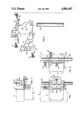
- FIG. 1 is a view partly in phantom by dotted lines to illustrate the positioning which the device will provide and certain of the elements thereof to locate a box as desired.
- FIG. 2 is a view similar to FIG. 1, but at right angle thereto.
- FIG. 3 is a plan view to show the positions of the device and relationship to an electrical box.
- FIG. 4 is an exploded view showing the device with its various parts in their related positions and as the device is adapted to be supported on a leg by which the height of installation of an electrical box will be determined.
- the device hereof comprises a body generally denoted 1 which is basically a flat member and has certain bent up or bent out parts and forms, the purpose of which will be understood as this description proceeds.
- the body includes a pair of flat parts or stud engaging legs, the upper one denoted 2 and the lower one denoted 3, such parts being provided to engage a stud or part of the frame of a building, the stud shown in fragmentary dotted lines at 4, in the various Figures.
- an outlet box is of generally rectilinear configuration having an open side, and whether of plastic or metal, the outlet or switch being ultimately positioned therewithin and within opening, and as such is gripped by the device hereof by means of gripping means, a lower one designated 6 and an upper one designated 7, the lower means being integral with the body 1 and extending out of the plane thereof at about right angles thereto.
- the part 7 is adjustable upwardly and downwardly and by means of a thumb screw 8 may be fastened in the proper position, and as such arranged to grip the box 9 therebetween, the thumb screw 8 being tightened to hold the box in the desired position.
- a clamping element 10 is provided, arranged so that by means of its configuration as a flat part with tongue areas 11 and 12 extending therefrom in the plane thereof, and a part 13 which includes an elongated slot 14 therein to engage a pin 15 on the body 1.
- a thumb screw 16 is arranged to hold the element 10 in the position of FIG. 1 against the surface of the body, the element may thus be moved back and forth for adjusting purposes.
- certain gauge marks three in number in this disclosure, and designated at 17 for the upper ones and 18 for the lower marks, to cooperate with the edge of the tongues 11 and 12 designated 11a and 12a to thereby establish the depth at which the box is to be secured, within the wall formed by the studs.
- edges 11a and 12a are related to the marks 17 and 18, to show the depth or thickness of the wall covering such as drywall or other material used for covering the studs to form the finished wall.
- the marks may establish any preferred increments for the positioning just before described.
- leg designated 20 is supplied as by a piece of electrical conduit or tubing as shown, adapted to be received in certain leg receiving parts 21 for the upper part and 22 for the lower edge of the body 1.
- the entire device is supported on the leg at any preferred position by a thumb screw 23 engaging the conduit or leg part 20 as may be desirably predetermined, and infinitely variable therealong.
- the clamping element 10 is provided with a portion 10a which engages an edge or lip of a box 9 and holding the box between the gripping means 6 and 7 in their adjusted position.
- the body is adjusted on the leg 20 at the desired position and as shown in FIG. 3 and by engaging the legs 2 and 3 against a stud 4, and in cooperation with the side of a box 9, locates the box and facilitates the fastening of the same to a stud 4.
Landscapes
- Engineering & Computer Science (AREA)
- Architecture (AREA)
- Civil Engineering (AREA)
- Structural Engineering (AREA)
- Connection Or Junction Boxes (AREA)
Abstract
Description
Claims (4)
Priority Applications (1)
| Application Number | Priority Date | Filing Date | Title |
|---|---|---|---|
| US07/275,572 US4901447A (en) | 1988-11-23 | 1988-11-23 | Electrical outlet and switchbox positioning device |
Applications Claiming Priority (1)
| Application Number | Priority Date | Filing Date | Title |
|---|---|---|---|
| US07/275,572 US4901447A (en) | 1988-11-23 | 1988-11-23 | Electrical outlet and switchbox positioning device |
Publications (1)
| Publication Number | Publication Date |
|---|---|
| US4901447A true US4901447A (en) | 1990-02-20 |
Family
ID=23052896
Family Applications (1)
| Application Number | Title | Priority Date | Filing Date |
|---|---|---|---|
| US07/275,572 Expired - Lifetime US4901447A (en) | 1988-11-23 | 1988-11-23 | Electrical outlet and switchbox positioning device |
Country Status (1)
| Country | Link |
|---|---|
| US (1) | US4901447A (en) |
Cited By (14)
| Publication number | Priority date | Publication date | Assignee | Title |
|---|---|---|---|---|
| US4703736A (en) * | 1986-09-25 | 1987-11-03 | Chrysler Motors Corporation | Fuel vapor containment device |
| US5067247A (en) * | 1991-03-22 | 1991-11-26 | Gilbert Milichichi | Apparatus for installing a box into a wall |
| US5072523A (en) * | 1990-12-24 | 1991-12-17 | Dickson Product Development, Inc. | Electrical box mounting tool |
| US5491901A (en) * | 1994-12-01 | 1996-02-20 | Parrino; Peter A. | Mechanical depthsetting device |
| US5813130A (en) * | 1997-05-05 | 1998-09-29 | Macdowell; Robert P. | Electrical gem box leveling template |
| US5992036A (en) * | 1997-12-29 | 1999-11-30 | Cannelli, Jr.; Victor | Tool for installing electrical outlet boxes |
| US6220317B1 (en) | 1999-10-20 | 2001-04-24 | Pass & Seymour, Inc. | Router template assembly |
| US6708421B1 (en) * | 2002-12-16 | 2004-03-23 | David J. Crorey | Locating device |
| US6818824B1 (en) | 2004-03-19 | 2004-11-16 | Cooper Wiring Devices, Inc. | Wiring device ganging tool |
| US20080148586A1 (en) * | 2006-12-21 | 2008-06-26 | Morin Joseph A | Installation gauge for electrical fixtures |
| US20080216335A1 (en) * | 2007-03-06 | 2008-09-11 | Crorey David J | Ceiling locating device |
| US20100126031A1 (en) * | 2008-11-24 | 2010-05-27 | Crorey David J | Flexible Locating Device |
| US20180231363A1 (en) * | 2017-02-13 | 2018-08-16 | Ronnie Alder Trent | Electrical box installation tool |
| US20230258209A1 (en) * | 2021-04-19 | 2023-08-17 | Victor Manuel Flores | Electrical Box Connection to a Support Rod |
Citations (4)
| Publication number | Priority date | Publication date | Assignee | Title |
|---|---|---|---|---|
| US2956798A (en) * | 1959-04-27 | 1960-10-18 | Uniprod Corp | Electrician's hand tool for positioning switch boxes and the like |
| US2990172A (en) * | 1958-09-23 | 1961-06-27 | Gianotta Mario | Device for locating the position for mounting a gem box or the like |
| US3150304A (en) * | 1962-01-22 | 1964-09-22 | Honeywell Regulator Co | Follow-up control apparatus for motor |
| US3436070A (en) * | 1966-05-31 | 1969-04-01 | Charles H Utley | Jig for electrical outlet boxes |
-
1988
- 1988-11-23 US US07/275,572 patent/US4901447A/en not_active Expired - Lifetime
Patent Citations (4)
| Publication number | Priority date | Publication date | Assignee | Title |
|---|---|---|---|---|
| US2990172A (en) * | 1958-09-23 | 1961-06-27 | Gianotta Mario | Device for locating the position for mounting a gem box or the like |
| US2956798A (en) * | 1959-04-27 | 1960-10-18 | Uniprod Corp | Electrician's hand tool for positioning switch boxes and the like |
| US3150304A (en) * | 1962-01-22 | 1964-09-22 | Honeywell Regulator Co | Follow-up control apparatus for motor |
| US3436070A (en) * | 1966-05-31 | 1969-04-01 | Charles H Utley | Jig for electrical outlet boxes |
Cited By (18)
| Publication number | Priority date | Publication date | Assignee | Title |
|---|---|---|---|---|
| US4703736A (en) * | 1986-09-25 | 1987-11-03 | Chrysler Motors Corporation | Fuel vapor containment device |
| US5072523A (en) * | 1990-12-24 | 1991-12-17 | Dickson Product Development, Inc. | Electrical box mounting tool |
| US5067247A (en) * | 1991-03-22 | 1991-11-26 | Gilbert Milichichi | Apparatus for installing a box into a wall |
| US5491901A (en) * | 1994-12-01 | 1996-02-20 | Parrino; Peter A. | Mechanical depthsetting device |
| US5813130A (en) * | 1997-05-05 | 1998-09-29 | Macdowell; Robert P. | Electrical gem box leveling template |
| US5992036A (en) * | 1997-12-29 | 1999-11-30 | Cannelli, Jr.; Victor | Tool for installing electrical outlet boxes |
| US6220317B1 (en) | 1999-10-20 | 2001-04-24 | Pass & Seymour, Inc. | Router template assembly |
| US6708421B1 (en) * | 2002-12-16 | 2004-03-23 | David J. Crorey | Locating device |
| US6818824B1 (en) | 2004-03-19 | 2004-11-16 | Cooper Wiring Devices, Inc. | Wiring device ganging tool |
| US20080148586A1 (en) * | 2006-12-21 | 2008-06-26 | Morin Joseph A | Installation gauge for electrical fixtures |
| US20080216335A1 (en) * | 2007-03-06 | 2008-09-11 | Crorey David J | Ceiling locating device |
| US7434327B2 (en) | 2007-03-06 | 2008-10-14 | Crorey David J | Ceiling locating device |
| US20100126031A1 (en) * | 2008-11-24 | 2010-05-27 | Crorey David J | Flexible Locating Device |
| US7926195B2 (en) | 2008-11-24 | 2011-04-19 | Crorey David J | Flexible locating device |
| US20180231363A1 (en) * | 2017-02-13 | 2018-08-16 | Ronnie Alder Trent | Electrical box installation tool |
| US10731961B2 (en) * | 2017-02-13 | 2020-08-04 | Ronnie Alder Trent | Electrical box installation tool |
| US20230258209A1 (en) * | 2021-04-19 | 2023-08-17 | Victor Manuel Flores | Electrical Box Connection to a Support Rod |
| US11802579B2 (en) * | 2021-04-19 | 2023-10-31 | Victor Manuel Flores | Electrical box connection to a support rod |
Similar Documents
| Publication | Publication Date | Title |
|---|---|---|
| US4901447A (en) | Electrical outlet and switchbox positioning device | |
| US5111593A (en) | Template for positioning outlet boxes | |
| US4301767A (en) | Holding clamp for an aquarium heater | |
| US4599485A (en) | Electrical receptacle box assembly | |
| US5813130A (en) | Electrical gem box leveling template | |
| US2990172A (en) | Device for locating the position for mounting a gem box or the like | |
| US6012690A (en) | Support for mounting containers without requiring tools | |
| US4114327A (en) | Light fixture support | |
| US2956798A (en) | Electrician's hand tool for positioning switch boxes and the like | |
| US6223445B1 (en) | Remodel box installation tool and method | |
| US4850115A (en) | Tool for positioning electrical outlet and junction boxes | |
| US5522149A (en) | Siding application and gauge tool | |
| US7373730B2 (en) | Tool for installing electrical boxes | |
| US6463668B1 (en) | Locating and template apparatus | |
| US5505001A (en) | Switch level | |
| US6820868B1 (en) | Fascia board hanger | |
| US20050051546A1 (en) | Adjustable electrical box | |
| US4750271A (en) | Template for locating electrical outlet boxes | |
| US4888879A (en) | Electrical junction box installer | |
| US5157844A (en) | Precision blind marking and positioning system for locating cutouts in wall openings | |
| US4635372A (en) | Apparatus for positioning an electrical box | |
| US10065305B2 (en) | Transfer tool for cabinet holes | |
| US5295644A (en) | Bracket for mounting an electrical outlet box | |
| US4432518A (en) | Eaves trough bracket assembly | |
| US5873568A (en) | Gutter holding pliers |
Legal Events
| Date | Code | Title | Description |
|---|---|---|---|
| REMI | Maintenance fee reminder mailed | ||
| FEPP | Fee payment procedure |
Free format text: PETITION RELATED TO MAINTENANCE FEES FILED (ORIGINAL EVENT CODE: PMFP); ENTITY STATUS OF PATENT OWNER: SMALL ENTITY Free format text: PETITION RELATED TO MAINTENANCE FEES DENIED/DISMISSED (ORIGINAL EVENT CODE: PMFD); ENTITY STATUS OF PATENT OWNER: SMALL ENTITY |
|
| REIN | Reinstatement after maintenance fee payment confirmed | ||
| FP | Lapsed due to failure to pay maintenance fee |
Effective date: 19930220 |
|
| FEPP | Fee payment procedure |
Free format text: PETITION RELATED TO MAINTENANCE FEES FILED (ORIGINAL EVENT CODE: PMFP); ENTITY STATUS OF PATENT OWNER: SMALL ENTITY |
|
| FEPP | Fee payment procedure |
Free format text: PETITION RELATED TO MAINTENANCE FEES GRANTED (ORIGINAL EVENT CODE: PMFG); ENTITY STATUS OF PATENT OWNER: SMALL ENTITY |
|
| FPAY | Fee payment |
Year of fee payment: 4 |
|
| SULP | Surcharge for late payment | ||
| STCF | Information on status: patent grant |
Free format text: PATENTED CASE |
|
| PRDP | Patent reinstated due to the acceptance of a late maintenance fee |
Effective date: 19960322 |
|
| FPAY | Fee payment |
Year of fee payment: 8 |