US4901442A - Vehicle wheel toe-in testing device - Google Patents
Vehicle wheel toe-in testing device Download PDFInfo
- Publication number
- US4901442A US4901442A US07/238,815 US23881588A US4901442A US 4901442 A US4901442 A US 4901442A US 23881588 A US23881588 A US 23881588A US 4901442 A US4901442 A US 4901442A
- Authority
- US
- United States
- Prior art keywords
- vehicle wheel
- valve
- chamber
- sensor member
- base plate
- Prior art date
- Legal status (The legal status is an assumption and is not a legal conclusion. Google has not performed a legal analysis and makes no representation as to the accuracy of the status listed.)
- Expired - Fee Related
Links
- 238000012360 testing method Methods 0.000 title claims abstract description 56
- 239000012530 fluid Substances 0.000 claims description 50
- 230000001276 controlling effect Effects 0.000 claims description 7
- 230000003287 optical effect Effects 0.000 claims description 4
- 230000001105 regulatory effect Effects 0.000 claims description 4
- 238000013101 initial test Methods 0.000 claims 1
- 238000005096 rolling process Methods 0.000 claims 1
- 238000010586 diagram Methods 0.000 description 4
- 238000001514 detection method Methods 0.000 description 2
- 238000004519 manufacturing process Methods 0.000 description 2
- 230000001133 acceleration Effects 0.000 description 1
- 238000012986 modification Methods 0.000 description 1
- 230000004048 modification Effects 0.000 description 1
Images


Classifications
-
- G—PHYSICS
- G01—MEASURING; TESTING
- G01B—MEASURING LENGTH, THICKNESS OR SIMILAR LINEAR DIMENSIONS; MEASURING ANGLES; MEASURING AREAS; MEASURING IRREGULARITIES OF SURFACES OR CONTOURS
- G01B13/00—Measuring arrangements characterised by the use of fluids
- G01B13/18—Measuring arrangements characterised by the use of fluids for measuring angles or tapers; for testing the alignment of axes
- G01B13/195—Measuring arrangements characterised by the use of fluids for measuring angles or tapers; for testing the alignment of axes for testing wheel alignment
Definitions
- the present invention relates to a vehicle wheel testing device for detecting the alignment of a vehicle wheel rotating at a testing speed, and in particular, to a toe-in tester for detecting the toe-in of a wheel of a vehicle as the vehicle moves along a production line.
- Prior art vehicle wheel alignment testing devices are known for detecting the toe-in and/or camber angles of vehicle wheels while the vehicle wheels rotate at a testing speed on a pair of support rollers.
- These prior art testing devices typically comprise a sensor plate with or without a plurality of rollers that is mounted in the device for relative movement and is initially brought into contact with the vehicle wheel. The wheel is then rotated and accelerated. As the wheels begin rotating, the toe-in of the wheels causes the vehicle to shift laterally on the support rollers until the vehicle becomes disposed at a testing position. Once the vehicle is in the testing position, relative movement of the sensor plate and/or rollers mounted thereto is then sensed to determine the toe-in and/or camber angles of the vehicle wheel.
- an object of the present invention is to provide a vehicle wheel testing device for detecting the alignment of a rotating vehicle wheel in which the vehicle wheel can attain a testing position on support rollers, after a sensor member has been urged into contact with the vehicle wheel, in a period of time which reduces the total test time to under 10 seconds.
- the present invention is characterized in the provision of control means which first urges a sensor member into contact with the vehicle wheel under a relatively low force while the vehicle wheel begins to rotate so as not to overly retard the lateral movement of the vehicle wheel on the support rollers.
- the control means causes the sensor member in contact with the vehicle wheel to be urged thereagainst under a relatively high force which is sufficient to facilitate the testing thereof.
- the toe-in can then be determined in approximately 5 seconds during this testing stage. In this way, the total testing time can be reduced to under 10 seconds.
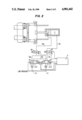
- FIG. 1 is a schematic plan diagram of an apparatus according to the present invention showing a set-up stage during the operation of the present invention
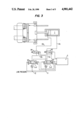
- FIG. 2 is a schematic plan diagram of an apparatus of FIG. 1 but showing a start-up stage during the operation of the apparatus of the present invention at which the vehicle wheel begins to rotate and shift laterally toward a testing position on support rollers;
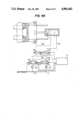
- FIG. 3 is a schematic plan diagram of the apparatus of FIG. 1 but showing the operation during a testing stage thereof during which the alignment of the vehicle wheel is detected once the vehicle wheel has reached the testing position;
- FIGS. 4A and 4B are respective schematic plan diagrams of the apparatus of FIG. 1 but showing the operation during alternative modes of a removal stage.
- the present invention comprises a base plate 1 slidably mounted in the device and guide means 2a2b for slidably guiding the base plate toward and away from a vehicle wheel 3.
- the vehicle wheel 3 is supported atop support rollers (shown in phantom lines) so as to rotate thereon when accelerated.
- a sensor member, generally indicated at 4 is carried by the base plate 1 for sliding therewith, and mounting means 5 mounts the sensor member 4 to the base plate 1 for allowing the sensor member to move relative to the base plate 1.
- the sensor member 4 comprises a roller supporting plate 4a and a plurality of rollers 4b, 4c rotatably mounted to the roller-supporting plate 4a.
- An urging means is operatively connected to the base plate 1 for urging the base plate and the sensor member 4 toward the vehicle wheel to place the sensor member 4 in contact with the vehicle wheel and for urging the sensor member 4 against the vehicle wheel.
- the urging means comprises a piston/cylinder device including a cylinder 6a, a piston 6b slidably received in the cylinder 6a, and a piston rod 6c connected to the piston 6b and the base plate 1.
- a first chamber 7 is defined between the cylinder and one side of the piston 6b while a second chamber 8 is defined between the cylinder 6a and the other side of the piston 6b.
- pressure generated in the first chamber 7 causes the piston 6b to slide in the cylinder 6a in a first direction (to the left in the Figures) in which the base plate 1 is moved toward the vehicle wheel 3 via piston rod 6c
- fluid pressure generated in the second chamber 8 causes the piston 6b to slide in the cylinder 6a in a direction (to the right in the Figures) in which the base plate 1 is moved away from the vehicle wheel via piston rod 6c.
- Control means is operatively connected to the urging means 6 for controlling the urging means to place the sensor member 4 in contact with the vehicle wheel during a set-up stage, for controlling the urging means 6 to urge the sensor member 4 in contact with the vehicle wheel against the vehicle wheel with an initial relatively low force as the vehicle wheel is rotationally accelerated and shifts laterally on the support rollers during a start-up stage, and for subsequently controlling the urging means to urge the sensor member 4 against the vehicle wheel with a relatively high testing force that is higher than said initial force, once the shifting of the vehicle wheel on the support rollers is completed during a testing stage.
- the control means then controls the urging means 6 to remove the sensor member 4 from the vehicle wheel once the testing is completed.
- the control means comprises a high pressure fluid line 11 in operative hydraulic communication with the first chamber 7 for passing high pressure fluid from a fluid source (not illustrated) to the first chamber (via lines 11a, 11b), and a low pressure fluid line 12 in operative hydraulic communication with the first chamber 7 (via lines 12a, 11a,11b) for passing low pressure fluid to the first chamber 7 from a fluid pressure source.
- Pressure regulating means R 1 , R 2 regulates the pressure in the high pressure fluid line 11 and the low pressure fluid line 12.
- the pressure regulator R 2 of the high pressure fluid line regulates the pressure of the fluid passing therein to 3 kg/cm 2 while the pressure regulator R 1 of the low pressure line 12 regulates the pressure of fluid flowing therein to 1kg/cm 2 .
- the control means further comprises a first valve V1 operatively hydraulically connected between the high pressure fluid line 11 and the first chamber 7 via lines 11a and 11b, and a second valve V2 operatively hydraulically connected between the low pressure fluid line 12 and the first chamber 7 via lines 12a, 11a and 11b.
- the second chamber 8 is also in operative hydraulic communication with the high fluid pressure line 11 through said first valve V1 via lines 12b and 12c, and the second chamber 8 is in operative hydraulic communication with the low pressure fluid line 12 through the second valve V2 via lines 12b, 12d.
- the control means comprises a third valve V3 which is operatively hydraulically connected between the first valve V1 and the first chamber 7 via lines 11a, 11b, and also between the second valve V2 and the first chamber 7 via lines 12a, 11a and 11b.
- a fourth valve V4 is operatively hydraulically connected between the second valve V2 and the second chamber 8 via lines 12d, 12b and between the second chamber 8 and the first valve V1 via lines 12b, 12c.
- valves V1-V4 of the present invention are multi-position directional flow control valves having respective solenoids S 1 -S 6 that actuate the valves to the positions shown in the Figures.
- a controller C is operatively connected to the solenoids S 1 -S 6 of the valves V1-V4 for actuating the valves during the operation of the present invention which will now be described with reference to FIGS. 1-3, 4A and 4B.
- FIG. 1 shows a set-up stage at which the sensor member 4, and in particular the rollers 4b, 4c, are moved into contact with the vehicle wheel 3 under a relatively high force.
- valve V1 is actuated by controller C to an open position thereof (by switching S 1 OFF and S 2 ON) while valve V3 is actuated to a first position thereof (by switching S 5 OFF) whereby fluid from high pressure line 11 is allowed to pass into chamber 7 via lines 11A, 11B thereby generating a relatively high pressure in chamber 7 which causes the piston 6b to slide to the left in the Figure and urge rollers 4b, 4c into contact with the vehicle wheel 3.
- Valve V4 is actuated to a second position (by switching S 6 ON) thereof and valve V2 is in a closed position thereof (by switching S 3 and S 4 OFF) whereby fluid from chamber 8 is directed through lines 12b and 12c to a drain or sump via valve V1. At this time, the vehicle wheel is not rotating.
- valve V1 to a closed position thereof (by switching S 2 OFF) and valve V2 to an open position thereof (by switching S 3 ON) whereby fluid pressure from the low pressure line 12 is directed to chamber 7 via line 12a, valve V3 which remains in the first position thereof, and line 11b.
- the drain or sump remains in communication with chamber 8 via line 12b, valve V4 which remains in the second position thereof, line 12d and valve V2 now in the open position thereof.
- the vehicle wheel begins to rotate and is accelerated toward the testing speed. Because of the relatively low force at which the sensor member 4 is urged against the vehicle wheel 3, the vehicle wheel can easily shift laterally on the support rollers to a testing position in approximately 3 seconds.
- the sensor member 4 is urged against the vehicle wheel 3 under a relatively high force which is larger than the force at which the sensor member 4 was previously urged against the vehicle wheel during the start-up stage shown in FIG. 2.
- the position of the valves V1-V4 are actuated to the same positions as those shown in FIG. 1 in the set-up stage. Therefore, again, high pressure fluid is directed to chamber 7 from high fluid pressure line 11. The valves remain in these positions during the testing stage for approximately 5 seconds while the actual detection of the alignment of the vehicle wheel 3 is performed.
- the detection is performed by detecting means comprising a pair of spaced apart optical detectors O 1 , O 2 each of which is mounted in the device at a respective location spaced from the sensor member 4.
- Each optical sensor O 1 , O 2 enses the distance between the location at which the sensor is mounted in the device and the sensor member 4.
- the mounting means 5 comprises a vertically extending pivot pin about which the sensor member 4 can rotate relative to the base plate 1.
- the sensor member 4 is moved away from the vehicle wheel during a removal stage which can be either a low pressure removal mode at which the sensor member 4 is removed from the vehicle wheel under a relatively low force and therefore at a relatively low speed or a high pressure removal mode during which the sensor member is removed from the vehicle wheel under a relatively high force at a relatively high speed.
- FIG. 4A shows the low pressure removal mode.
- valve V1 is actuated to the closed position thereof (by switching S 2 OFF) while valve V2 is actuated to a drain position thereof (by switching S 3 ON), and valve V3 is actuated to a second position thereof (by switching S 5 ON) while valve V4 is actuated to a first position thereof (by switching S 6 OFF).
- fluid flowing in the low pressure line 12 passes through valve V2 to chamber 8 via line 12d, valve V4 and line 12b while fluid in chamber 7 is drained via line 11b, valve V3, line 11a, line 12a and valve V2.
- valve V1 is moved to a drain position thereof (by switching S 1 ON and S 2 OFF) while valve V2 remains in the closed position thereof.
- Valve V3, as in the low pressure removal mode, is actuated to the second position thereof (by switching S 5 ON), while valve V4 is actuated to the first position thereof (by switching S 6 OFF).
- fluid pressure in the high pressure fluid line 11 passes to the high pressure chamber 8 via valve V1, lines 11a, 12c, valve V4 and line 12b while fluid in chamber 7 is communicated with the drain or sump via line 11b, valve V3, line 11a and valve V1.
Landscapes
- Physics & Mathematics (AREA)
- General Physics & Mathematics (AREA)
- A Measuring Device Byusing Mechanical Method (AREA)
- Testing Of Devices, Machine Parts, Or Other Structures Thereof (AREA)
Abstract
Description
Claims (13)
Priority Applications (2)
| Application Number | Priority Date | Filing Date | Title |
|---|---|---|---|
| US07/238,815 US4901442A (en) | 1988-08-31 | 1988-08-31 | Vehicle wheel toe-in testing device |
| JP1228181A JPH0367147A (en) | 1988-08-31 | 1989-08-31 | Vehicle wheel alignment testing apparatus |
Applications Claiming Priority (1)
| Application Number | Priority Date | Filing Date | Title |
|---|---|---|---|
| US07/238,815 US4901442A (en) | 1988-08-31 | 1988-08-31 | Vehicle wheel toe-in testing device |
Publications (1)
| Publication Number | Publication Date |
|---|---|
| US4901442A true US4901442A (en) | 1990-02-20 |
Family
ID=22899434
Family Applications (1)
| Application Number | Title | Priority Date | Filing Date |
|---|---|---|---|
| US07/238,815 Expired - Fee Related US4901442A (en) | 1988-08-31 | 1988-08-31 | Vehicle wheel toe-in testing device |
Country Status (2)
| Country | Link |
|---|---|
| US (1) | US4901442A (en) |
| JP (1) | JPH0367147A (en) |
Cited By (12)
| Publication number | Priority date | Publication date | Assignee | Title |
|---|---|---|---|---|
| US5105547A (en) * | 1990-07-24 | 1992-04-21 | Mazda Motor Corporation | Method of and apparatus for measuring the wheel alignment of automotive vehicles |
| US5111585A (en) * | 1989-11-21 | 1992-05-12 | Iyasaka Seiki Co., Ltd. | Method and apparatus for measuring and adjusting the wheel alignment of automotive vehicles |
| US5249364A (en) * | 1990-05-25 | 1993-10-05 | Dana Corporation | Front axle toe-in inspection process and apparatus |
| US5513438A (en) * | 1994-08-29 | 1996-05-07 | Emmons; J. Bruce | Vehicle wheel alignment system |
| US5818574A (en) * | 1995-09-05 | 1998-10-06 | Sun Electric U.K. Limited | Method and apparatus for vehicle wheel alignment testing |
| US6058614A (en) * | 1997-06-06 | 2000-05-09 | Honda Giken Kogyo Kabushiki Kaisha | Apparatus for measuring alignment of suspension and method of inspecting suspension by using said apparatus |
| US20020104374A1 (en) * | 2001-02-07 | 2002-08-08 | Merendino Paul A. | Method for controlling pneumatic tire pressures during dynamic vehicle test procedures |
| US6578275B1 (en) * | 2001-08-17 | 2003-06-17 | Akron Special Machinery, Inc. | Loadwheel drive assembly and method |
| US20040055169A1 (en) * | 2000-12-13 | 2004-03-25 | Akira Hirano | Wheel alignment measuring method and apparatus |
| WO2005008172A1 (en) * | 2003-07-18 | 2005-01-27 | Lasatron Ag | Method and device for measuring the steering geometry of vehicles |
| US20100292897A1 (en) * | 2008-01-09 | 2010-11-18 | Thomas Hub | Vehicle Centering in a Chassis Alignment Stand and Associated Method |
| CN118961119A (en) * | 2024-08-12 | 2024-11-15 | 徐州大泰机电科技有限公司 | Electric vehicle test platform |
Citations (10)
| Publication number | Priority date | Publication date | Assignee | Title |
|---|---|---|---|---|
| US3187440A (en) * | 1961-08-18 | 1965-06-08 | Merrill | Dynamic wheel alignment testing apparatus |
| US3453740A (en) * | 1966-08-23 | 1969-07-08 | Anzen Motor Car | Apparatus for checking the wheel alignment of an automobile |
| US3546782A (en) * | 1968-06-25 | 1970-12-15 | Applied Power Ind Inc | Automotive wheel alining apparatus |
| US3908280A (en) * | 1973-07-24 | 1975-09-30 | Banzai Jidosha Kabushiki Kaish | Roller drive-type compound vehicle wheel alignment tester |
| DE3225899A1 (en) * | 1982-07-10 | 1984-01-12 | Wegmann & Co GmbH, 3500 Kassel | DEVICE FOR MEASURING THE WHEEL LEVELS OF MOTOR VEHICLES |
| US4429467A (en) * | 1980-06-10 | 1984-02-07 | Toyota Jidosha Kogyo Kabushiki Kaisha | Apparatus for measuring toe-in of a motor vehicle wheel |
| US4443951A (en) * | 1980-07-17 | 1984-04-24 | Mauser-Werke Oberndorf Gmbh | Arrangement for the measuring and correcting of the steering geometry of motor vehicles |
| US4457075A (en) * | 1980-12-15 | 1984-07-03 | Toyota Jidosha Kogyo Kabushiki Kaisha | Method and an apparatus for measuring wheel alignment of motor vehicles |
| US4631832A (en) * | 1985-04-24 | 1986-12-30 | Wegmann & Co. Gmbh | Device for measuring axle geometry of motor vehicles with the wheels turning |
| US4679327A (en) * | 1986-07-07 | 1987-07-14 | Chrysler Motors Corporation | Front wheel drive vehicle, automatic toe set alignment system, therefor |
-
1988
- 1988-08-31 US US07/238,815 patent/US4901442A/en not_active Expired - Fee Related
-
1989
- 1989-08-31 JP JP1228181A patent/JPH0367147A/en active Pending
Patent Citations (10)
| Publication number | Priority date | Publication date | Assignee | Title |
|---|---|---|---|---|
| US3187440A (en) * | 1961-08-18 | 1965-06-08 | Merrill | Dynamic wheel alignment testing apparatus |
| US3453740A (en) * | 1966-08-23 | 1969-07-08 | Anzen Motor Car | Apparatus for checking the wheel alignment of an automobile |
| US3546782A (en) * | 1968-06-25 | 1970-12-15 | Applied Power Ind Inc | Automotive wheel alining apparatus |
| US3908280A (en) * | 1973-07-24 | 1975-09-30 | Banzai Jidosha Kabushiki Kaish | Roller drive-type compound vehicle wheel alignment tester |
| US4429467A (en) * | 1980-06-10 | 1984-02-07 | Toyota Jidosha Kogyo Kabushiki Kaisha | Apparatus for measuring toe-in of a motor vehicle wheel |
| US4443951A (en) * | 1980-07-17 | 1984-04-24 | Mauser-Werke Oberndorf Gmbh | Arrangement for the measuring and correcting of the steering geometry of motor vehicles |
| US4457075A (en) * | 1980-12-15 | 1984-07-03 | Toyota Jidosha Kogyo Kabushiki Kaisha | Method and an apparatus for measuring wheel alignment of motor vehicles |
| DE3225899A1 (en) * | 1982-07-10 | 1984-01-12 | Wegmann & Co GmbH, 3500 Kassel | DEVICE FOR MEASURING THE WHEEL LEVELS OF MOTOR VEHICLES |
| US4631832A (en) * | 1985-04-24 | 1986-12-30 | Wegmann & Co. Gmbh | Device for measuring axle geometry of motor vehicles with the wheels turning |
| US4679327A (en) * | 1986-07-07 | 1987-07-14 | Chrysler Motors Corporation | Front wheel drive vehicle, automatic toe set alignment system, therefor |
Cited By (15)
| Publication number | Priority date | Publication date | Assignee | Title |
|---|---|---|---|---|
| US5111585A (en) * | 1989-11-21 | 1992-05-12 | Iyasaka Seiki Co., Ltd. | Method and apparatus for measuring and adjusting the wheel alignment of automotive vehicles |
| US5249364A (en) * | 1990-05-25 | 1993-10-05 | Dana Corporation | Front axle toe-in inspection process and apparatus |
| US5105547A (en) * | 1990-07-24 | 1992-04-21 | Mazda Motor Corporation | Method of and apparatus for measuring the wheel alignment of automotive vehicles |
| US5513438A (en) * | 1994-08-29 | 1996-05-07 | Emmons; J. Bruce | Vehicle wheel alignment system |
| US5818574A (en) * | 1995-09-05 | 1998-10-06 | Sun Electric U.K. Limited | Method and apparatus for vehicle wheel alignment testing |
| US6058614A (en) * | 1997-06-06 | 2000-05-09 | Honda Giken Kogyo Kabushiki Kaisha | Apparatus for measuring alignment of suspension and method of inspecting suspension by using said apparatus |
| US6836970B2 (en) * | 2000-12-13 | 2005-01-04 | Honda Giken Kogyo Kabushiki Kaisha | Wheel alignment measuring method and apparatus |
| US20040055169A1 (en) * | 2000-12-13 | 2004-03-25 | Akira Hirano | Wheel alignment measuring method and apparatus |
| US20020104374A1 (en) * | 2001-02-07 | 2002-08-08 | Merendino Paul A. | Method for controlling pneumatic tire pressures during dynamic vehicle test procedures |
| US6578275B1 (en) * | 2001-08-17 | 2003-06-17 | Akron Special Machinery, Inc. | Loadwheel drive assembly and method |
| WO2005008172A1 (en) * | 2003-07-18 | 2005-01-27 | Lasatron Ag | Method and device for measuring the steering geometry of vehicles |
| US20060168827A1 (en) * | 2003-07-18 | 2006-08-03 | Lasatron Ag | Method and device for measuring the steering geometry of vehicles |
| US20100292897A1 (en) * | 2008-01-09 | 2010-11-18 | Thomas Hub | Vehicle Centering in a Chassis Alignment Stand and Associated Method |
| US9772184B2 (en) * | 2008-01-09 | 2017-09-26 | Siemens Aktiengesellschaft | Vehicle centering in a chassis alignment stand and associated method |
| CN118961119A (en) * | 2024-08-12 | 2024-11-15 | 徐州大泰机电科技有限公司 | Electric vehicle test platform |
Also Published As
| Publication number | Publication date |
|---|---|
| JPH0367147A (en) | 1991-03-22 |
Similar Documents
| Publication | Publication Date | Title |
|---|---|---|
| US4901442A (en) | Vehicle wheel toe-in testing device | |
| JP4011632B2 (en) | Automatic width adjusting chuck device for tire testing equipment | |
| JPS60198B2 (en) | Sheet material processing equipment with magnetic holding device | |
| JPS61262424A (en) | Drawing mechanism for strip | |
| CA1298273C (en) | Positioning apparatus for vehicle body | |
| EP2545354A1 (en) | Tire testing apparatus having adjustable bead width | |
| US2709588A (en) | Web guide means for a paper machine | |
| CN106927402A (en) | The jacking equipment of ground conveying machine and the load on the load-receipt device of ground conveying machine is unloaded the method being placed on discharge face | |
| US5402674A (en) | Method and apparatus for automatically restraining a vehicle on a test stand | |
| US5330126A (en) | Cup sidewall stock unwind stand | |
| EP0803722A2 (en) | Suspension rolling tester | |
| US3504835A (en) | Web registry control apparatus | |
| KR200186044Y1 (en) | Automatic reduction force control apparatus of skin pass mill | |
| US5086963A (en) | Web guidance and tracking mechanism for a continuous belt filter | |
| KR101846346B1 (en) | Apparatus and method for measuring abrasion of tire | |
| JP2993312B2 (en) | Roll characteristic test equipment for vehicles | |
| JPS5744408A (en) | Controller for shifting rolling apparatus | |
| JPH07215549A (en) | Center pivot air turn web operating assembly | |
| JPH0573546B2 (en) | ||
| JP5020731B2 (en) | Chassis dynamometer positioning support device | |
| JPH05104422A (en) | Inner pipe inner pipe | |
| KR20010027506A (en) | Device for controlling direction of billy roll in strip grinder | |
| JP3424396B2 (en) | Dimension measuring device | |
| JPH10244309A (en) | Looper steering device in hot finish rolling mill and meandering control method of rolling mill | |
| JPH0295529A (en) | Static pressure guide method for movement body |
Legal Events
| Date | Code | Title | Description |
|---|---|---|---|
| AS | Assignment |
Owner name: MAZDA MOTOR MANUFACTURING (USA) CORPORATION, 1 MAZ Free format text: ASSIGNMENT OF ASSIGNORS INTEREST.;ASSIGNOR:FUJII, HIROSHI;REEL/FRAME:004960/0719 Effective date: 19880915 Owner name: MAZDA MOTOR MANUFACTURING (USA) CORPORATION, MICHI Free format text: ASSIGNMENT OF ASSIGNORS INTEREST;ASSIGNOR:FUJII, HIROSHI;REEL/FRAME:004960/0719 Effective date: 19880915 |
|
| AS | Assignment |
Owner name: AUTOALLIANCE INTERNATIONAL, INC., MICHIGAN Free format text: CHANGE OF NAME;ASSIGNOR:MAZDA MOTOR MANUFACTURING (USA) CORPORATION;REEL/FRAME:006445/0822 Effective date: 19930210 |
|
| FPAY | Fee payment |
Year of fee payment: 4 |
|
| FEPP | Fee payment procedure |
Free format text: PAYOR NUMBER ASSIGNED (ORIGINAL EVENT CODE: ASPN); ENTITY STATUS OF PATENT OWNER: LARGE ENTITY |
|
| REMI | Maintenance fee reminder mailed | ||
| LAPS | Lapse for failure to pay maintenance fees | ||
| FP | Lapsed due to failure to pay maintenance fee |
Effective date: 19980225 |
|
| STCH | Information on status: patent discontinuation |
Free format text: PATENT EXPIRED DUE TO NONPAYMENT OF MAINTENANCE FEES UNDER 37 CFR 1.362 |