US4901426A - Method of making a pedal rod - Google Patents
Method of making a pedal rod Download PDFInfo
- Publication number
- US4901426A US4901426A US07/312,464 US31246489A US4901426A US 4901426 A US4901426 A US 4901426A US 31246489 A US31246489 A US 31246489A US 4901426 A US4901426 A US 4901426A
- Authority
- US
- United States
- Prior art keywords
- piece
- spaced
- shank
- threaded
- flat
- Prior art date
- Legal status (The legal status is an assumption and is not a legal conclusion. Google has not performed a legal analysis and makes no representation as to the accuracy of the status listed.)
- Expired - Fee Related
Links
- 238000004519 manufacturing process Methods 0.000 title claims abstract 4
- 239000000463 material Substances 0.000 claims abstract description 7
- 229910000831 Steel Inorganic materials 0.000 claims description 4
- 239000010959 steel Substances 0.000 claims description 4
- 238000002788 crimping Methods 0.000 claims description 3
- 239000002184 metal Substances 0.000 claims description 2
- 238000000034 method Methods 0.000 claims 5
- 230000006835 compression Effects 0.000 description 9
- 238000007906 compression Methods 0.000 description 9
- 238000002485 combustion reaction Methods 0.000 description 1
- 230000000295 complement effect Effects 0.000 description 1
- 238000005242 forging Methods 0.000 description 1
- 239000007788 liquid Substances 0.000 description 1
- 238000003754 machining Methods 0.000 description 1
- 239000007787 solid Substances 0.000 description 1
Images
Classifications
-
- B—PERFORMING OPERATIONS; TRANSPORTING
- B60—VEHICLES IN GENERAL
- B60T—VEHICLE BRAKE CONTROL SYSTEMS OR PARTS THEREOF; BRAKE CONTROL SYSTEMS OR PARTS THEREOF, IN GENERAL; ARRANGEMENT OF BRAKING ELEMENTS ON VEHICLES IN GENERAL; PORTABLE DEVICES FOR PREVENTING UNWANTED MOVEMENT OF VEHICLES; VEHICLE MODIFICATIONS TO FACILITATE COOLING OF BRAKES
- B60T7/00—Brake-action initiating means
- B60T7/02—Brake-action initiating means for personal initiation
- B60T7/08—Brake-action initiating means for personal initiation hand actuated
-
- B—PERFORMING OPERATIONS; TRANSPORTING
- B23—MACHINE TOOLS; METAL-WORKING NOT OTHERWISE PROVIDED FOR
- B23P—METAL-WORKING NOT OTHERWISE PROVIDED FOR; COMBINED OPERATIONS; UNIVERSAL MACHINE TOOLS
- B23P11/00—Connecting or disconnecting metal parts or objects by metal-working techniques not otherwise provided for
- B23P11/005—Connecting or disconnecting metal parts or objects by metal-working techniques not otherwise provided for by expanding or crimping
-
- B—PERFORMING OPERATIONS; TRANSPORTING
- B60—VEHICLES IN GENERAL
- B60T—VEHICLE BRAKE CONTROL SYSTEMS OR PARTS THEREOF; BRAKE CONTROL SYSTEMS OR PARTS THEREOF, IN GENERAL; ARRANGEMENT OF BRAKING ELEMENTS ON VEHICLES IN GENERAL; PORTABLE DEVICES FOR PREVENTING UNWANTED MOVEMENT OF VEHICLES; VEHICLE MODIFICATIONS TO FACILITATE COOLING OF BRAKES
- B60T13/00—Transmitting braking action from initiating means to ultimate brake actuator with power assistance or drive; Brake systems incorporating such transmitting means, e.g. air-pressure brake systems
- B60T13/10—Transmitting braking action from initiating means to ultimate brake actuator with power assistance or drive; Brake systems incorporating such transmitting means, e.g. air-pressure brake systems with fluid assistance, drive, or release
- B60T13/24—Transmitting braking action from initiating means to ultimate brake actuator with power assistance or drive; Brake systems incorporating such transmitting means, e.g. air-pressure brake systems with fluid assistance, drive, or release the fluid being gaseous
- B60T13/46—Vacuum systems
- B60T13/52—Vacuum systems indirect, i.e. vacuum booster units
-
- F—MECHANICAL ENGINEERING; LIGHTING; HEATING; WEAPONS; BLASTING
- F16—ENGINEERING ELEMENTS AND UNITS; GENERAL MEASURES FOR PRODUCING AND MAINTAINING EFFECTIVE FUNCTIONING OF MACHINES OR INSTALLATIONS; THERMAL INSULATION IN GENERAL
- F16B—DEVICES FOR FASTENING OR SECURING CONSTRUCTIONAL ELEMENTS OR MACHINE PARTS TOGETHER, e.g. NAILS, BOLTS, CIRCLIPS, CLAMPS, CLIPS OR WEDGES; JOINTS OR JOINTING
- F16B39/00—Locking of screws, bolts or nuts
- F16B39/02—Locking of screws, bolts or nuts in which the locking takes place after screwing down
-
- F—MECHANICAL ENGINEERING; LIGHTING; HEATING; WEAPONS; BLASTING
- F16—ENGINEERING ELEMENTS AND UNITS; GENERAL MEASURES FOR PRODUCING AND MAINTAINING EFFECTIVE FUNCTIONING OF MACHINES OR INSTALLATIONS; THERMAL INSULATION IN GENERAL
- F16B—DEVICES FOR FASTENING OR SECURING CONSTRUCTIONAL ELEMENTS OR MACHINE PARTS TOGETHER, e.g. NAILS, BOLTS, CIRCLIPS, CLAMPS, CLIPS OR WEDGES; JOINTS OR JOINTING
- F16B39/00—Locking of screws, bolts or nuts
- F16B39/22—Locking of screws, bolts or nuts in which the locking takes place during screwing down or tightening
- F16B39/28—Locking of screws, bolts or nuts in which the locking takes place during screwing down or tightening by special members on, or shape of, the nut or bolt
- F16B39/30—Locking exclusively by special shape of the screw-thread
-
- Y—GENERAL TAGGING OF NEW TECHNOLOGICAL DEVELOPMENTS; GENERAL TAGGING OF CROSS-SECTIONAL TECHNOLOGIES SPANNING OVER SEVERAL SECTIONS OF THE IPC; TECHNICAL SUBJECTS COVERED BY FORMER USPC CROSS-REFERENCE ART COLLECTIONS [XRACs] AND DIGESTS
- Y10—TECHNICAL SUBJECTS COVERED BY FORMER USPC
- Y10S—TECHNICAL SUBJECTS COVERED BY FORMER USPC CROSS-REFERENCE ART COLLECTIONS [XRACs] AND DIGESTS
- Y10S188/00—Brakes
- Y10S188/01—Panic braking
-
- Y—GENERAL TAGGING OF NEW TECHNOLOGICAL DEVELOPMENTS; GENERAL TAGGING OF CROSS-SECTIONAL TECHNOLOGIES SPANNING OVER SEVERAL SECTIONS OF THE IPC; TECHNICAL SUBJECTS COVERED BY FORMER USPC CROSS-REFERENCE ART COLLECTIONS [XRACs] AND DIGESTS
- Y10—TECHNICAL SUBJECTS COVERED BY FORMER USPC
- Y10T—TECHNICAL SUBJECTS COVERED BY FORMER US CLASSIFICATION
- Y10T29/00—Metal working
- Y10T29/49—Method of mechanical manufacture
- Y10T29/49826—Assembling or joining
- Y10T29/49908—Joining by deforming
- Y10T29/49915—Overedge assembling of seated part
- Y10T29/49917—Overedge assembling of seated part by necking in cup or tube wall
-
- Y—GENERAL TAGGING OF NEW TECHNOLOGICAL DEVELOPMENTS; GENERAL TAGGING OF CROSS-SECTIONAL TECHNOLOGIES SPANNING OVER SEVERAL SECTIONS OF THE IPC; TECHNICAL SUBJECTS COVERED BY FORMER USPC CROSS-REFERENCE ART COLLECTIONS [XRACs] AND DIGESTS
- Y10—TECHNICAL SUBJECTS COVERED BY FORMER USPC
- Y10T—TECHNICAL SUBJECTS COVERED BY FORMER US CLASSIFICATION
- Y10T29/00—Metal working
- Y10T29/49—Method of mechanical manufacture
- Y10T29/49826—Assembling or joining
- Y10T29/49908—Joining by deforming
- Y10T29/49925—Inward deformation of aperture or hollow body wall
- Y10T29/49927—Hollow body is axially joined cup or tube
- Y10T29/49929—Joined to rod
-
- Y—GENERAL TAGGING OF NEW TECHNOLOGICAL DEVELOPMENTS; GENERAL TAGGING OF CROSS-SECTIONAL TECHNOLOGIES SPANNING OVER SEVERAL SECTIONS OF THE IPC; TECHNICAL SUBJECTS COVERED BY FORMER USPC CROSS-REFERENCE ART COLLECTIONS [XRACs] AND DIGESTS
- Y10—TECHNICAL SUBJECTS COVERED BY FORMER USPC
- Y10T—TECHNICAL SUBJECTS COVERED BY FORMER US CLASSIFICATION
- Y10T29/00—Metal working
- Y10T29/49—Method of mechanical manufacture
- Y10T29/49826—Assembling or joining
- Y10T29/49945—Assembling or joining by driven force fit
-
- Y—GENERAL TAGGING OF NEW TECHNOLOGICAL DEVELOPMENTS; GENERAL TAGGING OF CROSS-SECTIONAL TECHNOLOGIES SPANNING OVER SEVERAL SECTIONS OF THE IPC; TECHNICAL SUBJECTS COVERED BY FORMER USPC CROSS-REFERENCE ART COLLECTIONS [XRACs] AND DIGESTS
- Y10—TECHNICAL SUBJECTS COVERED BY FORMER USPC
- Y10T—TECHNICAL SUBJECTS COVERED BY FORMER US CLASSIFICATION
- Y10T74/00—Machine element or mechanism
- Y10T74/20—Control lever and linkage systems
- Y10T74/20528—Foot operated
-
- Y—GENERAL TAGGING OF NEW TECHNOLOGICAL DEVELOPMENTS; GENERAL TAGGING OF CROSS-SECTIONAL TECHNOLOGIES SPANNING OVER SEVERAL SECTIONS OF THE IPC; TECHNICAL SUBJECTS COVERED BY FORMER USPC CROSS-REFERENCE ART COLLECTIONS [XRACs] AND DIGESTS
- Y10—TECHNICAL SUBJECTS COVERED BY FORMER USPC
- Y10T—TECHNICAL SUBJECTS COVERED BY FORMER US CLASSIFICATION
- Y10T74/00—Machine element or mechanism
- Y10T74/21—Elements
- Y10T74/2142—Pitmans and connecting rods
- Y10T74/2151—Longitudinally adjustable
-
- Y—GENERAL TAGGING OF NEW TECHNOLOGICAL DEVELOPMENTS; GENERAL TAGGING OF CROSS-SECTIONAL TECHNOLOGIES SPANNING OVER SEVERAL SECTIONS OF THE IPC; TECHNICAL SUBJECTS COVERED BY FORMER USPC CROSS-REFERENCE ART COLLECTIONS [XRACs] AND DIGESTS
- Y10—TECHNICAL SUBJECTS COVERED BY FORMER USPC
- Y10T—TECHNICAL SUBJECTS COVERED BY FORMER US CLASSIFICATION
- Y10T74/00—Machine element or mechanism
- Y10T74/21—Elements
- Y10T74/2142—Pitmans and connecting rods
- Y10T74/2152—Hollow rod, lubricated
Definitions
- This invention relates to brakes for automotive vehicles and more particularly to such a brake wherein an annular resiliant diaphram is clamped around its outer perimeter by a pair of annular housing or shell members defining spaced vacuum chambers at opposite sides of the diaphram.
- the diaphram has a central opening tightly clamping an annular valve body in an air-tight snap fit within an annular groove thereof.
- the valve body is urged into one of the vacuum chambers in response to pressure of an operator's foot on a brake pedal urging a pedal rod into the valve body and thereby urging the valve body against a compression rod assembly which in turn actuates the piston of a conventional master cylinder containing liquid which actuates the pistons of the wheel brakes.
- the present invention relates to the pedal rod which according to prior art practices consisted of a solid steel rod formed of forged and machined steel.
- a primary object of the invention is to form the end-piece of the pedal rod which is attached to the brake pedal of a different metal than the remainder of the pedal rod which transmits compression to the valve body under load of the order of 3,000 pounds or more during panic braking whereas release spring pressure to put the rod under tension upon release of the brake pedal would not exceed a much lower value. For this reason the rod need not be as strong in tension as in compression, although the illustrated form of my pedal rod is equally strong in compression and tension and will test safely in tension at 3,000 pounds.
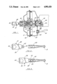
- FIG. 1 is a schematic axial sectional view, partly in elevation, of a power brake unit comprising an embodiment of the pedal rod made according to the invention
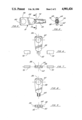
- FIG. 2 is an exploded side elevational view of said embodiment of the pedal rod before crimping of the shaft piece to the end-piece;
- FIG. 3 is a side elevational view of the pedal rod shown in FIG. 2 partly broken away;
- FIG. 4 is a fragmentary side elevational view of the pedal rod shown in FIG. 2 after crimping of the shaft piece;
- FIG. 5 is a sectional view taken on line 5--5 of FIG. 4;
- FIG. 6 is a schematic top plan view of the end-piece and the dies which form the threads thereon;
- FIG. 7 is a view taken from the bottom of FIG. 6;
- FIG. 8 is a top plan view of the end-piece with the threads thereon.
- FIG. 9 is a view taken from the bottom of FIG. 8.
- the power brake unit is conventional except for the pedal rod generally designated 10 (hereinafter described in detail), the button end 12 of which is received in a complementary, cylindrical recess or socket 14 of an annular valve body 16 which has an annular recess or groove 18 having an air-tight snap fit with the inner diameter of an annular resilient diaphram 20, the outer diameter of which is clamped by a pair of annular shell or housing members 21 and 22.
- the pedal rod generally designated 10 (hereinafter described in detail)
- the button end 12 of which is received in a complementary, cylindrical recess or socket 14 of an annular valve body 16 which has an annular recess or groove 18 having an air-tight snap fit with the inner diameter of an annular resilient diaphram 20, the outer diameter of which is clamped by a pair of annular shell or housing members 21 and 22.
- the valve body 16 comprises a seat 24 for a rubber pad 26 engaged by a large end 28 of a compression rod assembly 30 which has a smaller plunger end 32 received within a conventional master brake cylinder 34 removeably attached to the shell 22.
- the plunger end 32 of the compression rod assembly tightly engages the master cylinder piston 36 at 38 for actuation thereof as hereinafter described.
- the diaphram 20 defines spaced vacuum chambers 40 and 42 within the shells 21 and 22, respectively, both of said chambers being connected in the usual manner to intake manifold (not shown) of the vehicle's internal combustion engine through a hose 44 and check valve 46.
- valve 48 closes, cutting off atmospheric pressure from chamber 28 and reconnecting it to chamber 30 so that chamber 28 is again under vacuum, whereupon the resiliency of the diaphram 20 and a return spring 54 in chamber 42 returns the parts to non-brake position shown in FIG. 1.
- the pedal rod 10 (FIG. 1) comprises an end-piece 56 which is formed of a free machining material such as punch-press steel stamped into the form of a flat strap 58 with an aperture or eye 60 therethrough adapted for connection to an associated brake pedal (not shown).
- the end-piece 56 also comprises flat lug or trunnion 62 having spaced curved surfaces 64 in threaded engagement with a shaft piece 66 at 68.
- the threaded engagement at 68 is along interference threads.
- FIGS. 6-9 show the manner of threading lug 62 by a pair of split dies 70 which simultaneously engage the curved surfaces 64 (FIG. 5) to impress the threads thereon at 64 without any rotation of the lug 62 or the dies 70.
- FIGS. 6 and 7 show the dies spaced from the lug 62.
- the dies 70 engage the lug 62 at the same time to form the threads thereon at 64 (FIGS. 8 and 9).
- the interference threads are capable of resisting unthreading forces of the order of 5-40 inch pounds or more.
- I can accomplish any torque range in assembly by moving one part of "split die” out of position either forward or backward. This slight maladjustment of the two halves develops a variable torque depending on the amount of adjustment.
- I also can move 1/2 of the split die to accomplish a uniform friction or drag on thread to maintain a uniform torque in both in and out directions.
- the end-piece 56 is threaded into the shaft piece at 68 (FIG. 3) with a sufficient force to seat the shaft piece at 72 (FIGS. 3 and 4) against the end-piece.
- the shaft piece may be crimped as at 74 against the flat surfaces of the lug 62 as best seen in FIGS. 4 and 5.
Landscapes
- Engineering & Computer Science (AREA)
- Mechanical Engineering (AREA)
- General Engineering & Computer Science (AREA)
- Transportation (AREA)
- Forging (AREA)
Abstract
Description
Claims (7)
Priority Applications (1)
| Application Number | Priority Date | Filing Date | Title |
|---|---|---|---|
| US07/312,464 US4901426A (en) | 1989-02-21 | 1989-02-21 | Method of making a pedal rod |
Applications Claiming Priority (1)
| Application Number | Priority Date | Filing Date | Title |
|---|---|---|---|
| US07/312,464 US4901426A (en) | 1989-02-21 | 1989-02-21 | Method of making a pedal rod |
Publications (1)
| Publication Number | Publication Date |
|---|---|
| US4901426A true US4901426A (en) | 1990-02-20 |
Family
ID=23211574
Family Applications (1)
| Application Number | Title | Priority Date | Filing Date |
|---|---|---|---|
| US07/312,464 Expired - Fee Related US4901426A (en) | 1989-02-21 | 1989-02-21 | Method of making a pedal rod |
Country Status (1)
| Country | Link |
|---|---|
| US (1) | US4901426A (en) |
Cited By (15)
| Publication number | Priority date | Publication date | Assignee | Title |
|---|---|---|---|---|
| US5230134A (en) * | 1992-02-11 | 1993-07-27 | Laue Charles E | Method of making a petal rod |
| US5308185A (en) * | 1992-12-17 | 1994-05-03 | Laue Charles E | Method and means of fastening two parts with an internally threaded folded fastener |
| EP0631900A1 (en) * | 1993-05-27 | 1995-01-04 | NAUE/JOHNSON CONTROLS ENGINEERING GmbH & CO. KG | Axial crimp connection for open planetary recliner |
| US5413013A (en) * | 1993-03-22 | 1995-05-09 | Haca Spare Parts Technology Inc. | Tie rod assembly for sand molding machine |
| US5425286A (en) * | 1993-04-09 | 1995-06-20 | Laue; Charles E. | Two piece pedal rod and method of making same |
| US5469761A (en) * | 1994-09-07 | 1995-11-28 | Charles E. Laue | Push rod button and method of making same |
| US5606790A (en) * | 1993-04-09 | 1997-03-04 | Charles E. Laue | Method of making a two piece pedal rod |
| US5685200A (en) * | 1994-10-21 | 1997-11-11 | Dr. Ing. H.C.F. Porsche Ag | Brake pressure rod |
| WO1998018581A1 (en) * | 1996-10-25 | 1998-05-07 | Laue Charles E | Method of locking a screw threaded joint |
| FR2757227A1 (en) * | 1996-12-17 | 1998-06-19 | Sarma | Method of mounting eyelet on end of link for aircraft components |
| US5774971A (en) * | 1996-12-31 | 1998-07-07 | Manetta; Peter J. | Method of manufacturing standardized pin-based parts |
| US6655230B1 (en) * | 2000-02-23 | 2003-12-02 | Ford Global Technologies, Llc | Vehicle pedal assembly |
| US20050262916A1 (en) * | 2004-05-28 | 2005-12-01 | B R Metal Products | Stamping apparatus for forming rod with configured ends |
| US20110049448A1 (en) * | 2009-09-03 | 2011-03-03 | Middleville Tool & Die Company, Inc. | Method for making threaded tube |
| CN116601061A (en) * | 2020-11-25 | 2023-08-15 | 罗伯特·博世有限公司 | Axial force transmitter for an actuating device of a brake system and method for producing the axial force transmitter |
Citations (9)
| Publication number | Priority date | Publication date | Assignee | Title |
|---|---|---|---|---|
| US856316A (en) * | 1905-02-25 | 1907-06-11 | Henry A Fowler | Extensible curtain-rod and method of making. |
| US2497384A (en) * | 1946-07-03 | 1950-02-14 | Jonas L Young | Removable utensil handle |
| US2596885A (en) * | 1948-07-27 | 1952-05-13 | Thompson Prod Inc | Lock joint for tie rod and end assemblies |
| US2869392A (en) * | 1955-08-13 | 1959-01-20 | Daimler Benz Ag | Foot pedal arrangement |
| US2881738A (en) * | 1956-11-29 | 1959-04-14 | Signode Steel Strapping Co | Piston and staple driver combination |
| US2884803A (en) * | 1956-09-26 | 1959-05-05 | Gen Motors Corp | Force applying lever and linkage system |
| US2900203A (en) * | 1957-12-12 | 1959-08-18 | Hayden Boyd | Turnbuckle for loom harness |
| US4500224A (en) * | 1983-07-22 | 1985-02-19 | Nss, Industries, Inc. | Coupling for sucker rod assembly |
| US4538339A (en) * | 1981-09-02 | 1985-09-03 | National Set Screw | Method of making a sucker rod assembly |
-
1989
- 1989-02-21 US US07/312,464 patent/US4901426A/en not_active Expired - Fee Related
Patent Citations (9)
| Publication number | Priority date | Publication date | Assignee | Title |
|---|---|---|---|---|
| US856316A (en) * | 1905-02-25 | 1907-06-11 | Henry A Fowler | Extensible curtain-rod and method of making. |
| US2497384A (en) * | 1946-07-03 | 1950-02-14 | Jonas L Young | Removable utensil handle |
| US2596885A (en) * | 1948-07-27 | 1952-05-13 | Thompson Prod Inc | Lock joint for tie rod and end assemblies |
| US2869392A (en) * | 1955-08-13 | 1959-01-20 | Daimler Benz Ag | Foot pedal arrangement |
| US2884803A (en) * | 1956-09-26 | 1959-05-05 | Gen Motors Corp | Force applying lever and linkage system |
| US2881738A (en) * | 1956-11-29 | 1959-04-14 | Signode Steel Strapping Co | Piston and staple driver combination |
| US2900203A (en) * | 1957-12-12 | 1959-08-18 | Hayden Boyd | Turnbuckle for loom harness |
| US4538339A (en) * | 1981-09-02 | 1985-09-03 | National Set Screw | Method of making a sucker rod assembly |
| US4500224A (en) * | 1983-07-22 | 1985-02-19 | Nss, Industries, Inc. | Coupling for sucker rod assembly |
Cited By (19)
| Publication number | Priority date | Publication date | Assignee | Title |
|---|---|---|---|---|
| US5456137A (en) * | 1992-02-11 | 1995-10-10 | Charles E. Laue | Pedal rods and a method of making the same |
| US5230134A (en) * | 1992-02-11 | 1993-07-27 | Laue Charles E | Method of making a petal rod |
| US5308185A (en) * | 1992-12-17 | 1994-05-03 | Laue Charles E | Method and means of fastening two parts with an internally threaded folded fastener |
| US5413013A (en) * | 1993-03-22 | 1995-05-09 | Haca Spare Parts Technology Inc. | Tie rod assembly for sand molding machine |
| US5606790A (en) * | 1993-04-09 | 1997-03-04 | Charles E. Laue | Method of making a two piece pedal rod |
| US5425286A (en) * | 1993-04-09 | 1995-06-20 | Laue; Charles E. | Two piece pedal rod and method of making same |
| EP0631900A1 (en) * | 1993-05-27 | 1995-01-04 | NAUE/JOHNSON CONTROLS ENGINEERING GmbH & CO. KG | Axial crimp connection for open planetary recliner |
| WO1996026024A1 (en) * | 1994-01-06 | 1996-08-29 | Laue Charles E | Two piece pedal rod and method of making same |
| US5469761A (en) * | 1994-09-07 | 1995-11-28 | Charles E. Laue | Push rod button and method of making same |
| US5685200A (en) * | 1994-10-21 | 1997-11-11 | Dr. Ing. H.C.F. Porsche Ag | Brake pressure rod |
| WO1998018581A1 (en) * | 1996-10-25 | 1998-05-07 | Laue Charles E | Method of locking a screw threaded joint |
| FR2757227A1 (en) * | 1996-12-17 | 1998-06-19 | Sarma | Method of mounting eyelet on end of link for aircraft components |
| US5774971A (en) * | 1996-12-31 | 1998-07-07 | Manetta; Peter J. | Method of manufacturing standardized pin-based parts |
| US6655230B1 (en) * | 2000-02-23 | 2003-12-02 | Ford Global Technologies, Llc | Vehicle pedal assembly |
| US20050262916A1 (en) * | 2004-05-28 | 2005-12-01 | B R Metal Products | Stamping apparatus for forming rod with configured ends |
| US7213436B2 (en) | 2004-05-28 | 2007-05-08 | Shape Corporation | Stamping apparatus for forming rod with configured ends |
| US20110049448A1 (en) * | 2009-09-03 | 2011-03-03 | Middleville Tool & Die Company, Inc. | Method for making threaded tube |
| US8356396B2 (en) | 2009-09-03 | 2013-01-22 | Middleville Tool & Die Company | Method for making threaded tube |
| CN116601061A (en) * | 2020-11-25 | 2023-08-15 | 罗伯特·博世有限公司 | Axial force transmitter for an actuating device of a brake system and method for producing the axial force transmitter |
Similar Documents
| Publication | Publication Date | Title |
|---|---|---|
| US4901426A (en) | Method of making a pedal rod | |
| US3802200A (en) | Plastic master cylinder | |
| JPH0749803B2 (en) | Ball joint | |
| US5771774A (en) | Spring brake actuator having plastic pressure plate assembly | |
| US5024298A (en) | Apparatus and method of automotive brake with booster piston | |
| JPS6241863Y2 (en) | ||
| US5456137A (en) | Pedal rods and a method of making the same | |
| US4784241A (en) | Integrated disc brake and drum rake construction | |
| US6062124A (en) | Brake booster | |
| US4008925A (en) | Valve devices for use in liquid pressure braking systems of vehicles | |
| JPS62157854A (en) | Connection method and device for master cylinder and vacuum brake booster device | |
| US4723638A (en) | Wheel angular acceleration sensor for a vehicle antilock control device | |
| US3981147A (en) | Master cylinder assembly | |
| AU709256B2 (en) | Spring brake actuator having plastic pressure plate assembly | |
| JPS6232126Y2 (en) | ||
| JP2772542B2 (en) | Hydraulic proportioning valve | |
| JPS6351864U (en) | ||
| JP2569533Y2 (en) | Brake switching valve | |
| JPH04230466A (en) | Method of adjusting jump value of brake booster and brake booster therefor | |
| KR19980073549A (en) | Dual proportional control valve for automotive master cylinder | |
| JPH0531297Y2 (en) | ||
| JPS6325399Y2 (en) | ||
| JPH0226966U (en) | ||
| JPS568744A (en) | Control valve for deceleration responsive hydraulic pressure | |
| JPH0343089Y2 (en) |
Legal Events
| Date | Code | Title | Description |
|---|---|---|---|
| AS | Assignment |
Owner name: CHARLES E. LAUE TRUST Free format text: ASSIGNMENT OF ASSIGNORS INTEREST.;ASSIGNOR:LAUE, CHARLES E.;REEL/FRAME:005340/0723 |
|
| FPAY | Fee payment |
Year of fee payment: 4 |
|
| AS | Assignment |
Owner name: LAUE, CHARLES E., PATENT TRUST OF 7/15/94, ILLINOI Free format text: ASSIGNMENT OF ASSIGNORS INTEREST;ASSIGNOR:LAUE, CHARLES E.;REEL/FRAME:008000/0840 Effective date: 19960514 Owner name: LAUE, CHARLES E., ILLINOIS Free format text: ASSIGNMENT OF ASSIGNORS INTEREST;ASSIGNOR:CHARLES E. LAUE TRUST OF FEBRUARY 2, 1970;REEL/FRAME:008000/0837 Effective date: 19960514 |
|
| FEPP | Fee payment procedure |
Free format text: PAYOR NUMBER ASSIGNED (ORIGINAL EVENT CODE: ASPN); ENTITY STATUS OF PATENT OWNER: SMALL ENTITY |
|
| FPAY | Fee payment |
Year of fee payment: 8 |
|
| REMI | Maintenance fee reminder mailed | ||
| LAPS | Lapse for failure to pay maintenance fees | ||
| STCH | Information on status: patent discontinuation |
Free format text: PATENT EXPIRED DUE TO NONPAYMENT OF MAINTENANCE FEES UNDER 37 CFR 1.362 |
|
| FP | Lapsed due to failure to pay maintenance fee |
Effective date: 20020220 |