US4901376A - Bathroom ventilator housing - Google Patents
Bathroom ventilator housing Download PDFInfo
- Publication number
- US4901376A US4901376A US07/229,475 US22947588A US4901376A US 4901376 A US4901376 A US 4901376A US 22947588 A US22947588 A US 22947588A US 4901376 A US4901376 A US 4901376A
- Authority
- US
- United States
- Prior art keywords
- housing
- cover element
- enclosure
- inlet
- walls
- Prior art date
- Legal status (The legal status is an assumption and is not a legal conclusion. Google has not performed a legal analysis and makes no representation as to the accuracy of the status listed.)
- Expired - Fee Related
Links
Images
Classifications
-
- H—ELECTRICITY
- H02—GENERATION; CONVERSION OR DISTRIBUTION OF ELECTRIC POWER
- H02G—INSTALLATION OF ELECTRIC CABLES OR LINES, OR OF COMBINED OPTICAL AND ELECTRIC CABLES OR LINES
- H02G3/00—Installations of electric cables or lines or protective tubing therefor in or on buildings, equivalent structures or vehicles
- H02G3/02—Details
- H02G3/08—Distribution boxes; Connection or junction boxes
- H02G3/081—Bases, casings or covers
- H02G3/083—Inlets
Definitions
- This invention relates to housings for bathroom ventilators or the like, and more particularly to an improved such housing having novel knockout hole and wiring compartment covers therefor.
- the Underwriter's Laboratory, Inc. sets industry guide lines for bathroom ventilator safety requirements. Among one such requirement is that the area surrounding a knockout portion of a ventilator housing--i.e., that portion of the housing which is knocked out to provide an ingress/egress hole or holes for the electrical wiring of the ventilator--must have a minimum thickness of 0.032".
- the National Electrical Code requires also that any unused knockout hole in the housing must be plugged.
- U.S. Pat. No. 3,981,069 discloses a knockout hole cover or support for a range-hood of the canopy type.
- the hole cover or support is adapted to be releasably secured over a knockout hole in the housing by means of a screw.
- the support itself has therein a hole to which the incoming power cable is mechanically coupled or clamped, after which the support, which is in the form of a disc, is secured over a hole that has been formed in the housing by punching out a knockout portion of the housing.
- the disadvantage of this construction is that it supports or consists of only one hole for accommodating one incoming cable, and does not cover any unused holes.
- Still another object of this invention is to provide an improved housing of the type described which has incorporated therein an inexpensive, removable wiring compartment cover which registers with selected portions of the housing walls to form therewith an outlet box or wiring compartment in the housing.
- the housing is generally rectangular in configuration and adjacent one corner thereof has in each of two of its intersecting walls a knockout hole or opening for accommodating power supply wires.
- a reversible, generally L-shaped knockout hole cover is removably secured to said housing with a hole in one leg thereof registering with one of said knockout holes, and with a knockout plug in its other leg overlying and covering the other knockout hole in the housing.
- Power supply wire are insertable through the registering openings in the housing and the L-shaped knockout cover, respectively, and are disposed to be connected in one corner of the housing to the leads of an electric motor.
- These wiring connections are located in a wiring compartment which is triangular in cross section, and which is defined by three of the intersecting walls of the housing, and a removable compartment cover.
- This cover comprises of a flat, rectangular section which extends diagonally between a pair of said intersecting housing walls, and which is engaged at its inner edge with a third wall of the housing.
- a flat, triangular section of the cover projects at right angles from the outer edge of rectangular cover section, and into the intersection formed by said pair of housing walls.
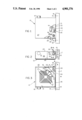
- FIG. 1 is a fragmentary plan view of a residential bathroom ventilator housing made according to one embodiment of this invention, the housing being shown mounted on one side of a ceiling joist for a bathroom, or the like, with portions of the housing being broken away and shown in section, and with part of an associated knockout cover or support being shown fragmentarily;
- FIG. 2 is a front elevational view of the housing shown in FIG. 1;
- FIG. 3 is a bottom plan view of the housing with a portion of its grill broken away to show a wiring compartment cover which is removably mounted in the housing, a portion of this cover also being cut away;
- FIG. 4 is an enlarged, fragmentary sectional view taken generally along the line 4--4 in FIG. 2 looking in the direction of the arrows, and illustrating one of two different positions in which the knockout support may be secured to the housing adjacent one corner thereof;
- FIG. 5 is a detail view of this knockout support as seen when looking at the left side of the housing as shown in FIG. 4, the support being shown as it appears before being secured to the housing;
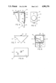
- FIG. 6 is an enlarged, fragmentary sectional view taken generally along the line 6--6 in FIG. 3 looking in the direction of the arrows;
- FIG. 7 is a front elevational detail view of the wiring compartment cover which is removably mounted in the housing, the cover being shown as it appears before being mounted in the housing;
- FIG. 8 is a plan view of the cover as shown in FIG. 7.
- 10 denotes generally a metal ventilator housing, which is rectangular in cross section, and which has a large, rectangular grille 12 secured in a conventional manner over its lower, open end.
- Grille 12 which may be of any conventional design, has therein the usual array of slots 12' which communicate with the interior of the housing so that, when the ventilator or exhaust fan 14 in the housing is rotated by its associated motor (not illustrated), air from the room will be drawn into the housing through the grille 12 and will be exhausted from the housing through a discharge duct 16.
- housing 10 also has projecting from opposed sidewalls thereof a pair of integral brackets 18 by means of which the housing can be mounted by screws 19 on the side of a ceiling joist J, or the like.
- Partition 21 Secured in housing 10 approximately midway between its upper and lower surfaces, and extending transversely across the center of the housing, is a rigid, rectangular partition 21.
- Partition 21 has in its center a large, circular opening 22 in which the fan 14 is mounted for coaxial rotation by conventional means which form no part of this invention.
- Partition 21 also has one corner portion thereof removed, thereby forming on the partition an inclined edge 23, (FIGS. 3 and 6) which extends diagonally between a pair of the intersecting sidewalls 25 and 26 of housing 10.
- housing 10 Adjacent the corner thereof formed by its intersection with housing sidewalls 25 and 26, the plane upper or top wall 27 of housing 10 has therein a circular wire inlet/outlet opening 28.
- a similar inlet/outlet opening 29 (FIG. 4) is formed in the housing wall 25 adjacent its intersection with housing wall 27.
- Numeral 30 denotes generally an L-shaped knockout support or cover element having a first leg section 32 overlying the housing inlet/outlet opening 29, and a second leg section 33, which extends at right angles from leg section 32 to overlie the opening 28 in the housing wall 27.
- a dog-legged shaped tang 34 Integral with and projecting centrally from the lower edge of leg section 32 is a dog-legged shaped tang 34, which projects releasably through a registering opening formed in the housing wall 25 beneath the circular opening 29.
- the leg section 32 also has formed therein, and centrally thereof, a circular knockout plug 35, which overlies and closes the opening 29 in the housing wall 25 when the support 30 is secured by screw 36 to the housing 10 as shown in FIGS. 2 and 4.
- the housing wall 27 has therein a smaller, circular opening 38, which, as noted hereinafter, can be utilized to accommodate the shank of the screw 36; and beneath the opening 28 the wall 27 has therein still another opening 39 for accommodating the tang 34 of the support 30, when the latter is disposed in a second position as noted hereinafter.
- the connection when the wires W are connected to the motor within the housing 10, it is essential that the connection be enclosed in an outlet box having a removable cover.
- the outlet box which is employed to enclose the connection between the wire W and the motor leads, is formed in part by the intersecting housing walls 25, 26 and 27, and by the legs of a removable cover element, which is denoted generally at 40 in the drawings.
- the cover element 40 comprises two, planar sections 41 and 44 which intersect each other at right angles.
- Section 41 as shown in FIGS. 7 and 8, is triangular in configuration and has a pair of inclined edges 42 and 43 which intersect each other at right angles.
- the other section 44 is rectangular in configuration, and has struck up from the center thereof a small, arcuate detent or lip 45 having an open end which faces in the direction of the cover section 41.
- Section 44 also has therein a circular opening 46 which is located adjacent one of the corners where the sections 41 and 44 intersect.
- the leads from the ventilator motor (not illustrated) are fed through the opening 46 in the cover element 40, and are connected to the wire leads W from the power supply, which enter housing 10 through the registering openings 37 and 28 (FIG. 4).
- These connections which of course also are insulated, are then positioned adjacent the intersection of the housing walls 25 and 26 by sliding the cover element 40 into the housing 10 in such manner that its rectangular section 44 passes or slides beneath the inclined edge 23 of the partition 21 until the inner edge of the cover section 44 engages the inside of the housing wall 27.
- the advantage of the knockout support 30 is that, when the housing is originally manufactured, the L-shaped support is adapted to be secured by the screw 36 in the position as shown in the drawings. This exposes opening 28, which is the wire inlet/outlet opening that is most frequently employed. However, should it be desired to utilize the other opening 29, it is possible to remove the screw 36, and to reverse the position of the support 30 so that the tab 34 will now be positioned in opening 39, and the screw 32 will be threaded into the opening 38 in the housing wall 27. This will cause the plug 35 now to be positioned over and to close the opening 28, while the opening 37 in the support 30 will now register with opening 29 to enable the power supply leads to be inserted or withdrawn through opening 29.
- the knockout support 30 operates to provide or support one knockout hole, while automatically sealing the other, unused hole.
- the support can be reversed, if desired, to open the previously sealed hole, and to seal the formerly open hole; or alternatively, the knockout plug can be removed to provide access to both openings 28 and 29.
- the cover does not require the use of any separate, mechanical means for securing it releasably in the housing.
- the cover does not require the use of any separate, mechanical means for securing it releasably in the housing.
- the cost of complying with the U.L. and the N.E.C. requirements is considerably reduced.
- this type of cover can be utilized without the use of any separate tools for inserting or withdrawing the cover.
Landscapes
- Engineering & Computer Science (AREA)
- Architecture (AREA)
- Civil Engineering (AREA)
- Structural Engineering (AREA)
- Connector Housings Or Holding Contact Members (AREA)
Abstract
Description
Claims (12)
Priority Applications (1)
| Application Number | Priority Date | Filing Date | Title |
|---|---|---|---|
| US07/229,475 US4901376A (en) | 1988-08-08 | 1988-08-08 | Bathroom ventilator housing |
Applications Claiming Priority (1)
| Application Number | Priority Date | Filing Date | Title |
|---|---|---|---|
| US07/229,475 US4901376A (en) | 1988-08-08 | 1988-08-08 | Bathroom ventilator housing |
Related Parent Applications (1)
| Application Number | Title | Priority Date | Filing Date |
|---|---|---|---|
| US89178986A Continuation-In-Part | 1985-03-28 | 1986-07-30 |
Related Child Applications (1)
| Application Number | Title | Priority Date | Filing Date |
|---|---|---|---|
| US07/517,526 Continuation US5256549A (en) | 1986-03-28 | 1990-04-27 | Purification of synthetic oligomers |
Publications (1)
| Publication Number | Publication Date |
|---|---|
| US4901376A true US4901376A (en) | 1990-02-20 |
Family
ID=22861400
Family Applications (1)
| Application Number | Title | Priority Date | Filing Date |
|---|---|---|---|
| US07/229,475 Expired - Fee Related US4901376A (en) | 1988-08-08 | 1988-08-08 | Bathroom ventilator housing |
Country Status (1)
| Country | Link |
|---|---|
| US (1) | US4901376A (en) |
Cited By (5)
| Publication number | Priority date | Publication date | Assignee | Title |
|---|---|---|---|---|
| USD325660S (en) | 1990-06-29 | 1992-04-21 | Rapaz Antonio R | Waste receptacle lid or the like |
| US5879232A (en) * | 1997-03-25 | 1999-03-09 | Tomkins Industries, Inc. | Exhaust fan |
| US20060065211A1 (en) * | 2004-09-01 | 2006-03-30 | Aos Holding Company | Blower and method of conveying fluids |
| US20090119944A1 (en) * | 2007-10-15 | 2009-05-14 | Lg Electronics Inc. | Clothing dryer |
| US20130130613A1 (en) * | 2010-07-30 | 2013-05-23 | Panasonic Corporation | Fire damper for ventilating fan |
Citations (7)
| Publication number | Priority date | Publication date | Assignee | Title |
|---|---|---|---|---|
| US642521A (en) * | 1899-12-18 | 1900-01-30 | Edwin T Greenfield | Junction-box for electrical conductors. |
| US892220A (en) * | 1908-06-30 | James F Burns | Junction-box for electrical conductors. | |
| US2349668A (en) * | 1940-08-02 | 1944-05-23 | Trade Wind Motorfans Inc | Blower |
| US2780981A (en) * | 1953-09-30 | 1957-02-12 | John K Miller | Ventilating apparatus |
| US2800849A (en) * | 1955-04-20 | 1957-07-30 | Nutone Inc | Ventilator unit |
| CA658728A (en) * | 1963-03-05 | H. Rudolph Nathan | Cable connector | |
| US3483309A (en) * | 1968-05-22 | 1969-12-09 | Itt | Snap-on cable clamp |
-
1988
- 1988-08-08 US US07/229,475 patent/US4901376A/en not_active Expired - Fee Related
Patent Citations (7)
| Publication number | Priority date | Publication date | Assignee | Title |
|---|---|---|---|---|
| US892220A (en) * | 1908-06-30 | James F Burns | Junction-box for electrical conductors. | |
| CA658728A (en) * | 1963-03-05 | H. Rudolph Nathan | Cable connector | |
| US642521A (en) * | 1899-12-18 | 1900-01-30 | Edwin T Greenfield | Junction-box for electrical conductors. |
| US2349668A (en) * | 1940-08-02 | 1944-05-23 | Trade Wind Motorfans Inc | Blower |
| US2780981A (en) * | 1953-09-30 | 1957-02-12 | John K Miller | Ventilating apparatus |
| US2800849A (en) * | 1955-04-20 | 1957-07-30 | Nutone Inc | Ventilator unit |
| US3483309A (en) * | 1968-05-22 | 1969-12-09 | Itt | Snap-on cable clamp |
Cited By (9)
| Publication number | Priority date | Publication date | Assignee | Title |
|---|---|---|---|---|
| USD325660S (en) | 1990-06-29 | 1992-04-21 | Rapaz Antonio R | Waste receptacle lid or the like |
| US5879232A (en) * | 1997-03-25 | 1999-03-09 | Tomkins Industries, Inc. | Exhaust fan |
| US20060065211A1 (en) * | 2004-09-01 | 2006-03-30 | Aos Holding Company | Blower and method of conveying fluids |
| US7354244B2 (en) | 2004-09-01 | 2008-04-08 | Aos Holding Company | Blower and method of conveying fluids |
| US20090119944A1 (en) * | 2007-10-15 | 2009-05-14 | Lg Electronics Inc. | Clothing dryer |
| US20130130613A1 (en) * | 2010-07-30 | 2013-05-23 | Panasonic Corporation | Fire damper for ventilating fan |
| US9533179B2 (en) * | 2010-07-30 | 2017-01-03 | Panasonic Ecology Systems Guangdong Co., Ltd. | Fire damper for ventilating fan |
| US20170028233A1 (en) * | 2010-07-30 | 2017-02-02 | Panasonic Ecology Systems Guangdong Co., Ltd. | Fire damper for ventilating fan |
| US9868003B2 (en) * | 2010-07-30 | 2018-01-16 | Panasonic Ecology Systems Guangdong Co., Ltd. | Fire damper for ventilating fan |
Similar Documents
| Publication | Publication Date | Title |
|---|---|---|
| US4265365A (en) | Moisture resistant electrical outlet box | |
| US3909589A (en) | Modular heating, lighting and ventilating unit | |
| KR100238512B1 (en) | Air conditioner for ceiling | |
| US4901376A (en) | Bathroom ventilator housing | |
| US5578791A (en) | Combined wall mount and electrical outlet box | |
| CN211400075U (en) | Window type air conditioner | |
| DE3664159D1 (en) | Ventilating device | |
| US7445546B2 (en) | Housing for an extractor hood and ventilator housing | |
| CN111059637A (en) | Window type air conditioner | |
| JP3819496B2 (en) | Air conditioner | |
| JPH0118992Y2 (en) | ||
| JP4341311B2 (en) | Electrical component and outdoor unit using it | |
| US6133530A (en) | Protective cover apparatus and method | |
| CN222773489U (en) | Electric control box and air conditioner | |
| JPH0519694Y2 (en) | ||
| CN222747354U (en) | Indoor unit and HVAC equipment | |
| CN206563415U (en) | Air processor | |
| JP3043219B2 (en) | Air conditioner | |
| JPH047462Y2 (en) | ||
| JP3813405B2 (en) | Electrical box and ceiling-mounted air conditioner | |
| JPH0650574A (en) | Heat exchanger | |
| JPS586189Y2 (en) | dehumidifier | |
| JPH0136039Y2 (en) | ||
| JPH0615234Y2 (en) | Air conditioner indoor unit | |
| US4085726A (en) | Forced air furnace motor lead wire protection |
Legal Events
| Date | Code | Title | Description |
|---|---|---|---|
| AS | Assignment |
Owner name: FASCO INDUSTRIES, INC., ONE WWESTMINSTER PLACE, LA Free format text: ASSIGNMENT OF ASSIGNORS INTEREST.;ASSIGNOR:IVEY, CHARLES W.;REEL/FRAME:004916/0965 Effective date: 19880801 |
|
| FEPP | Fee payment procedure |
Free format text: PAYOR NUMBER ASSIGNED (ORIGINAL EVENT CODE: ASPN); ENTITY STATUS OF PATENT OWNER: LARGE ENTITY |
|
| AS | Assignment |
Owner name: FASCO CONSUMER PRODUCTS, INC., NORTH CAROLINA Free format text: ASSIGNMENT OF ASSIGNORS INTEREST;ASSIGNOR:FASCO INDUSTRIES INC.;REEL/FRAME:006568/0893 Effective date: 19930520 |
|
| FPAY | Fee payment |
Year of fee payment: 4 |
|
| FEPP | Fee payment procedure |
Free format text: PAYER NUMBER DE-ASSIGNED (ORIGINAL EVENT CODE: RMPN); ENTITY STATUS OF PATENT OWNER: LARGE ENTITY Free format text: PAYOR NUMBER ASSIGNED (ORIGINAL EVENT CODE: ASPN); ENTITY STATUS OF PATENT OWNER: LARGE ENTITY |
|
| FPAY | Fee payment |
Year of fee payment: 8 |
|
| AS | Assignment |
Owner name: RIVAL COMPANY, THE (A DELAWARE CORPORATION), MISSO Free format text: ASSIGNMENT OF ASSIGNORS INTEREST;ASSIGNOR:FASCO CONSUMER PRODUCTS, INC., (A DELAWARE CORPORATION);REEL/FRAME:009893/0346 Effective date: 19970211 |
|
| AS | Assignment |
Owner name: BANKBOSTON, N.A., AS AGENT, MASSACHUSETTS Free format text: PATENT COLLATERAL ASSIGNMENT AND SECURITY AGREEMENT;ASSIGNOR:RIVAL COMPANY, THE;REEL/FRAME:009968/0802 Effective date: 19990205 |
|
| AS | Assignment |
Owner name: RIVAL COMPANY, THE, MISSOURI Free format text: PARTIAL TERMINATION & RELEASE;ASSIGNOR:BANKBOSTON, N.A.;REEL/FRAME:010719/0978 Effective date: 19991221 |
|
| AS | Assignment |
Owner name: MARLEY COMPANY, THE, SOUTH CAROLINA Free format text: ASSIGNMENT OF ASSIGNORS INTEREST;ASSIGNOR:RIVAL COMPANY, THE;REEL/FRAME:011400/0853 Effective date: 19991210 |
|
| AS | Assignment |
Owner name: MARLEY COMPANY, THE, NORTH CAROLINA Free format text: ASSIGNMENT OF ASSIGNORS INTEREST;ASSIGNOR:RIVAL COMPANY, THE;REEL/FRAME:012066/0801 Effective date: 19991210 |
|
| REMI | Maintenance fee reminder mailed | ||
| AS | Assignment |
Owner name: CHASE MANHATTAN BANK AS COLLATERAL AGENT, THE, TEX Free format text: SECURITY INTEREST;ASSIGNOR:MARLEY COMPANY (DE CORPORATION), THE;REEL/FRAME:012219/0449 Effective date: 20010710 |
|
| LAPS | Lapse for failure to pay maintenance fees | ||
| STCH | Information on status: patent discontinuation |
Free format text: PATENT EXPIRED DUE TO NONPAYMENT OF MAINTENANCE FEES UNDER 37 CFR 1.362 |
|
| FP | Lapsed due to failure to pay maintenance fee |
Effective date: 20020220 |
|
| AS | Assignment |
Owner name: MARLEY ENGINEERED PRODUCTS, LLC, NORTH CAROLINA Free format text: ASSIGNMENT OF ASSIGNORS INTEREST;ASSIGNOR:THE MARLEY COMPANY;REEL/FRAME:014119/0969 Effective date: 20030107 |
|
| AS | Assignment |
Owner name: THE RIVAL COMPANY, MASSACHUSETTS Free format text: RELEASE OF SECURITY INTEREST RECORDED AT REEL 009968 FRAME 0802;ASSIGNOR:FLEET NATIONAL BANK;REEL/FRAME:015065/0091 Effective date: 20040506 |
|
| AS | Assignment |
Owner name: THE MARLEY COMPANY LLC (FORMERLY KNOWN AS THE MARL Free format text: TERMINATION AND RELEASE OF SECURITY INTEREST IN PATENT RIGHTS (PREVIOUSLY RECORDED AT REEL 12219 FRAME 0449);ASSIGNOR:JPMORGAN CHASE BANK, N.A., AS COLLATERAL AGENT;REEL/FRAME:016851/0796 Effective date: 20051118 |