US4901297A - Optical magnetic recording and reproducing method and apparatus capable of prolonging a recording time - Google Patents
Optical magnetic recording and reproducing method and apparatus capable of prolonging a recording time Download PDFInfo
- Publication number
- US4901297A US4901297A US07/000,871 US87187A US4901297A US 4901297 A US4901297 A US 4901297A US 87187 A US87187 A US 87187A US 4901297 A US4901297 A US 4901297A
- Authority
- US
- United States
- Prior art keywords
- recording medium
- optical beam
- recording
- optical
- signal
- Prior art date
- Legal status (The legal status is an assumption and is not a legal conclusion. Google has not performed a legal analysis and makes no representation as to the accuracy of the status listed.)
- Expired - Fee Related
Links
Images


Classifications
-
- G—PHYSICS
- G11—INFORMATION STORAGE
- G11B—INFORMATION STORAGE BASED ON RELATIVE MOVEMENT BETWEEN RECORD CARRIER AND TRANSDUCER
- G11B7/00—Recording or reproducing by optical means, e.g. recording using a thermal beam of optical radiation by modifying optical properties or the physical structure, reproducing using an optical beam at lower power by sensing optical properties; Record carriers therefor
-
- G—PHYSICS
- G11—INFORMATION STORAGE
- G11B—INFORMATION STORAGE BASED ON RELATIVE MOVEMENT BETWEEN RECORD CARRIER AND TRANSDUCER
- G11B15/00—Driving, starting or stopping record carriers of filamentary or web form; Driving both such record carriers and heads; Guiding such record carriers or containers therefor; Control thereof; Control of operating function
- G11B15/60—Guiding record carrier
- G11B15/62—Maintaining desired spacing between record carrier and head
-
- G—PHYSICS
- G11—INFORMATION STORAGE
- G11B—INFORMATION STORAGE BASED ON RELATIVE MOVEMENT BETWEEN RECORD CARRIER AND TRANSDUCER
- G11B11/00—Recording on or reproducing from the same record carrier wherein for these two operations the methods are covered by different main groups of groups G11B3/00 - G11B7/00 or by different subgroups of group G11B9/00; Record carriers therefor
- G11B11/10—Recording on or reproducing from the same record carrier wherein for these two operations the methods are covered by different main groups of groups G11B3/00 - G11B7/00 or by different subgroups of group G11B9/00; Record carriers therefor using recording by magnetic means or other means for magnetisation or demagnetisation of a record carrier, e.g. light induced spin magnetisation; Demagnetisation by thermal or stress means in the presence or not of an orienting magnetic field
- G11B11/105—Recording on or reproducing from the same record carrier wherein for these two operations the methods are covered by different main groups of groups G11B3/00 - G11B7/00 or by different subgroups of group G11B9/00; Record carriers therefor using recording by magnetic means or other means for magnetisation or demagnetisation of a record carrier, e.g. light induced spin magnetisation; Demagnetisation by thermal or stress means in the presence or not of an orienting magnetic field using a beam of light or a magnetic field for recording by change of magnetisation and a beam of light for reproducing, i.e. magneto-optical, e.g. light-induced thermomagnetic recording, spin magnetisation recording, Kerr or Faraday effect reproducing
- G11B11/10502—Recording on or reproducing from the same record carrier wherein for these two operations the methods are covered by different main groups of groups G11B3/00 - G11B7/00 or by different subgroups of group G11B9/00; Record carriers therefor using recording by magnetic means or other means for magnetisation or demagnetisation of a record carrier, e.g. light induced spin magnetisation; Demagnetisation by thermal or stress means in the presence or not of an orienting magnetic field using a beam of light or a magnetic field for recording by change of magnetisation and a beam of light for reproducing, i.e. magneto-optical, e.g. light-induced thermomagnetic recording, spin magnetisation recording, Kerr or Faraday effect reproducing characterised by the transducing operation to be executed
- G11B11/10517—Overwriting or erasing
-
- G—PHYSICS
- G11—INFORMATION STORAGE
- G11B—INFORMATION STORAGE BASED ON RELATIVE MOVEMENT BETWEEN RECORD CARRIER AND TRANSDUCER
- G11B11/00—Recording on or reproducing from the same record carrier wherein for these two operations the methods are covered by different main groups of groups G11B3/00 - G11B7/00 or by different subgroups of group G11B9/00; Record carriers therefor
- G11B11/10—Recording on or reproducing from the same record carrier wherein for these two operations the methods are covered by different main groups of groups G11B3/00 - G11B7/00 or by different subgroups of group G11B9/00; Record carriers therefor using recording by magnetic means or other means for magnetisation or demagnetisation of a record carrier, e.g. light induced spin magnetisation; Demagnetisation by thermal or stress means in the presence or not of an orienting magnetic field
- G11B11/105—Recording on or reproducing from the same record carrier wherein for these two operations the methods are covered by different main groups of groups G11B3/00 - G11B7/00 or by different subgroups of group G11B9/00; Record carriers therefor using recording by magnetic means or other means for magnetisation or demagnetisation of a record carrier, e.g. light induced spin magnetisation; Demagnetisation by thermal or stress means in the presence or not of an orienting magnetic field using a beam of light or a magnetic field for recording by change of magnetisation and a beam of light for reproducing, i.e. magneto-optical, e.g. light-induced thermomagnetic recording, spin magnetisation recording, Kerr or Faraday effect reproducing
- G11B11/10532—Heads
-
- G—PHYSICS
- G11—INFORMATION STORAGE
- G11B—INFORMATION STORAGE BASED ON RELATIVE MOVEMENT BETWEEN RECORD CARRIER AND TRANSDUCER
- G11B11/00—Recording on or reproducing from the same record carrier wherein for these two operations the methods are covered by different main groups of groups G11B3/00 - G11B7/00 or by different subgroups of group G11B9/00; Record carriers therefor
- G11B11/10—Recording on or reproducing from the same record carrier wherein for these two operations the methods are covered by different main groups of groups G11B3/00 - G11B7/00 or by different subgroups of group G11B9/00; Record carriers therefor using recording by magnetic means or other means for magnetisation or demagnetisation of a record carrier, e.g. light induced spin magnetisation; Demagnetisation by thermal or stress means in the presence or not of an orienting magnetic field
- G11B11/105—Recording on or reproducing from the same record carrier wherein for these two operations the methods are covered by different main groups of groups G11B3/00 - G11B7/00 or by different subgroups of group G11B9/00; Record carriers therefor using recording by magnetic means or other means for magnetisation or demagnetisation of a record carrier, e.g. light induced spin magnetisation; Demagnetisation by thermal or stress means in the presence or not of an orienting magnetic field using a beam of light or a magnetic field for recording by change of magnetisation and a beam of light for reproducing, i.e. magneto-optical, e.g. light-induced thermomagnetic recording, spin magnetisation recording, Kerr or Faraday effect reproducing
- G11B11/1055—Disposition or mounting of transducers relative to record carriers
- G11B11/10576—Disposition or mounting of transducers relative to record carriers with provision for moving the transducers for maintaining alignment or spacing relative to the carrier
-
- G—PHYSICS
- G11—INFORMATION STORAGE
- G11B—INFORMATION STORAGE BASED ON RELATIVE MOVEMENT BETWEEN RECORD CARRIER AND TRANSDUCER
- G11B11/00—Recording on or reproducing from the same record carrier wherein for these two operations the methods are covered by different main groups of groups G11B3/00 - G11B7/00 or by different subgroups of group G11B9/00; Record carriers therefor
- G11B11/10—Recording on or reproducing from the same record carrier wherein for these two operations the methods are covered by different main groups of groups G11B3/00 - G11B7/00 or by different subgroups of group G11B9/00; Record carriers therefor using recording by magnetic means or other means for magnetisation or demagnetisation of a record carrier, e.g. light induced spin magnetisation; Demagnetisation by thermal or stress means in the presence or not of an orienting magnetic field
- G11B11/105—Recording on or reproducing from the same record carrier wherein for these two operations the methods are covered by different main groups of groups G11B3/00 - G11B7/00 or by different subgroups of group G11B9/00; Record carriers therefor using recording by magnetic means or other means for magnetisation or demagnetisation of a record carrier, e.g. light induced spin magnetisation; Demagnetisation by thermal or stress means in the presence or not of an orienting magnetic field using a beam of light or a magnetic field for recording by change of magnetisation and a beam of light for reproducing, i.e. magneto-optical, e.g. light-induced thermomagnetic recording, spin magnetisation recording, Kerr or Faraday effect reproducing
- G11B11/10595—Control of operating function
-
- G—PHYSICS
- G11—INFORMATION STORAGE
- G11B—INFORMATION STORAGE BASED ON RELATIVE MOVEMENT BETWEEN RECORD CARRIER AND TRANSDUCER
- G11B15/00—Driving, starting or stopping record carriers of filamentary or web form; Driving both such record carriers and heads; Guiding such record carriers or containers therefor; Control thereof; Control of operating function
- G11B15/18—Driving; Starting; Stopping; Arrangements for control or regulation thereof
- G11B15/46—Controlling, regulating, or indicating speed
- G11B15/467—Controlling, regulating, or indicating speed in arrangements for recording or reproducing wherein both record carriers and heads are driven
-
- G—PHYSICS
- G11—INFORMATION STORAGE
- G11B—INFORMATION STORAGE BASED ON RELATIVE MOVEMENT BETWEEN RECORD CARRIER AND TRANSDUCER
- G11B7/00—Recording or reproducing by optical means, e.g. recording using a thermal beam of optical radiation by modifying optical properties or the physical structure, reproducing using an optical beam at lower power by sensing optical properties; Record carriers therefor
- G11B7/002—Recording, reproducing or erasing systems characterised by the shape or form of the carrier
- G11B7/003—Recording, reproducing or erasing systems characterised by the shape or form of the carrier with webs, filaments or wires, e.g. belts, spooled tapes or films of quasi-infinite extent
-
- G—PHYSICS
- G11—INFORMATION STORAGE
- G11B—INFORMATION STORAGE BASED ON RELATIVE MOVEMENT BETWEEN RECORD CARRIER AND TRANSDUCER
- G11B7/00—Recording or reproducing by optical means, e.g. recording using a thermal beam of optical radiation by modifying optical properties or the physical structure, reproducing using an optical beam at lower power by sensing optical properties; Record carriers therefor
- G11B7/08—Disposition or mounting of heads or light sources relatively to record carriers
- G11B7/09—Disposition or mounting of heads or light sources relatively to record carriers with provision for moving the light beam or focus plane for the purpose of maintaining alignment of the light beam relative to the record carrier during transducing operation, e.g. to compensate for surface irregularities of the latter or for track following
- G11B7/0925—Electromechanical actuators for lens positioning
-
- H—ELECTRICITY
- H04—ELECTRIC COMMUNICATION TECHNIQUE
- H04N—PICTORIAL COMMUNICATION, e.g. TELEVISION
- H04N5/00—Details of television systems
- H04N5/76—Television signal recording
- H04N5/84—Television signal recording using optical recording
-
- H—ELECTRICITY
- H04—ELECTRIC COMMUNICATION TECHNIQUE
- H04N—PICTORIAL COMMUNICATION, e.g. TELEVISION
- H04N9/00—Details of colour television systems
- H04N9/79—Processing of colour television signals in connection with recording
- H04N9/80—Transformation of the television signal for recording, e.g. modulation, frequency changing; Inverse transformation for playback
- H04N9/82—Transformation of the television signal for recording, e.g. modulation, frequency changing; Inverse transformation for playback the individual colour picture signal components being recorded simultaneously only
Definitions
- the present invention relates to an optical magnetic recording and reproducing apparatus and more particularly to an optical magnetic recording and reproducing apparatus and method suitable to efficient recording and reproducing signals on a recording medium having a lengthwise direction such as magnetic tape.
- a recording track is formed in the traveling direction of the recording medium. It has been aimed to prolong the recording time.
- the recording track is formed in the lengthwise direction of the magnetic tape. Manipulation such as special reproduction or record head search used for reproduction becomes very difficult.
- An object of the present invention is to provide a scanning method and its signal processing method which are free from the above described drawbacks of the prior art, which facilitate prolonging the recording time, which are stable, and which can be easily manipulated.
- magnetic tape is used, for example.
- manipulation for reproduction such as special reproduction or head search is difficult. Even if the recording time can be prolonged, therefore, adoption of the prior art in products poses a problem.
- this problem is solved by adopting a system in which recording tracks are formed at a predetermined angle with respect to the lengthwise direction of the recording medium in the same way as conventional video tape recorders.
- a polygonal rotary scanner is used to form a recording track having a predetermined angle with respect to the traveling direction of the recording medium.
- tracking control is effected by either rotating the rotary scanner around two arbitrary axes perpendicular to the rotary axis or arbitrarily varying the beam direction of the optical beam generator. Otherwise, tracking control may be effected by a combination of the above described two methods.
- the recording light beam is preceded by the erasing beam light, and the sense of the current flowing through the electromagnetic coil is inverted by a changeover pulse track by track.
- all of the magnetic fields contained in one track have the same sense, and the sense of the magnetic field is inverted track by track.
- a part having no signals recorded thereon is caused because of irregular reflection of light beam incurred in the vicinity of the apex of the polygonal rotary scanner. Occurrence of such a part is coped with by effecting time base compression using the memory during recording and generating a section having no signals in the vicinity of the apex.
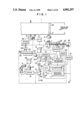
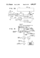
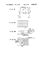
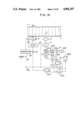
- FIG. 1 is a block diagram showing the entire system configuration of an optical magnetic recording and reproducing apparatus according to the present invention.
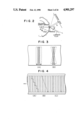
- FIG. 2 is a schematic diagram showing a polygonal rotary scanner and scanning of a recording medium.
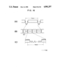
- FIG. 3 is a pattern diagram showing the track pattern on a recording medium.
- FIG. 4 is a schematic diagram showing the track scanning in special reproduction.
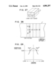
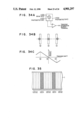
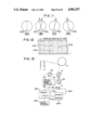
- FIGS. 5A and 5B are schematic diagrams showing the relationship between the rotary scanner and an optical path correction lens.
- FIGS. 6A and 6B are schematic diagrams showing other embodiments of the present invention using cylindrical tracking lenses.
- FIG. 7(A) to (F') are schematic diagrams showing the relationship between the cylindrical lens and the scanning position of the recording medium.
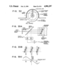
- FIG. 8 is a schematic diagram showing the erasing system of a magnetic field modulation system.
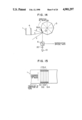
- FIGS. 9A, 9B and 9C are schematic diagrams showing the erasing system of an optical modulation system.
- FIG. 10 is a schematic diagram showing another tracking control system according to the present invention.
- FIG. 11(A) to (D) are schematic diagrams showing linear polarization at various parts of FIG. 10.
- FIG. 12 is a pattern diagram showing the magnetization pattern on the recording medium.
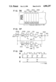
- FIG. 13 is a block diagram of an embodiment of the present invention equipped with a memory unit.
- FIG. 14 is a schematic diagram showing the range on the rotary scanner scanned by the time base compression signal.
- FIG. 15 is a schematic diagram showing the range on the recording medium scanned by the time base compression signal.
- FIG. 16(A), (B) and (C) are timing diagrams when a video signal undergoes time base compression and is recorded on four segments.
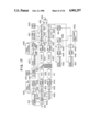
- FIG. 17 is a block diagram implementing the time base compression and expansion signal processing method.
- FIG. 18(A-E) are waveform diagram showing the waveform and timing of signal processing of FIG. 17.
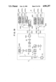
- FIG. 19 is a block diagram showing an embodiment of an optical magnetic recording and reproducing system.
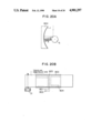
- FIGS. 20A and 20B are schematic diagrams showing an embodiment of the portion for making a recording medium travel according to the present invention.
- FIG. 21 is a block diagram showing another embodiment of the portion for making the recording medium travel.
- FIG. 22 is a block diagram showing an embodiment using a rotary scanner having a structure of a polygonal truncated pyramid.
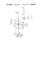
- FIG. 23 is a block diagram showing another embodiment of focus servomechanism.
- FIG. 24 is a block diagram showing an embodiment in which two kinds of signals are simultaneously recorded.
- FIG. 25 is a pattern diagram showing the track pattern of FIG. 24.
- FIG. 26(A-D) are timing diagrams of changeover switches shown in FIG. 24.
- FIG. 27 is an oblique view showing a light source of another embodiment in which two kinds of signals are recorded.
- FIG. 28 is a track pattern diagram of FIG. 27.
- FIG. 29 is a characteristic diagram showing the relationship between the tracking variation value and the reproduced signal level.
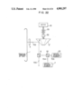
- FIG. 30 is a block diagram showing another embodiment of servocontrol according to the present invention.
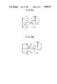
- FIG. 31 is a block diagram showing an embodiment of the present invention using a rotary cylinder.
- FIG. 32 is a configuration diagram showing the relationship between the rotary cylinder and the recording medium.
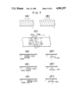
- FIGS. 33A, 33B and 33C are schematic diagrams showing a tracking control method according to the present invention.
- FIGS. 34A, 34B and 34C are schematic diagrams showing another tracking control method.
- FIG. 35 is a pattern diagram of a track exclusively used for tracking control in still another tracking control method.
- FIG. 36 is a pattern diagram of a track used in still another tracking control method.
- FIG. 37 is a circuit diagram of a tracking control circuit.
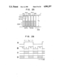
- FIG. 38 is a waveform diagram showing waveforms at various parts of FIG. 37.
- FIG. 1 showing an embodiment of the present invention, a recording medium 1 whereon signals are recorded by means of optical magnetic recording technique, a recording and reproducing laser oscillator 3, a focus lens 20, a polygonal rotary scanner 5 for scanning the recording medium with a laser beam, a track 34 formed when the recording medium 1 isscanned with the laser beam, a pilot information recording section 2 recorded on a part or the whole of the track 34 for tracking control, an erasing laser oscillator 27, a beam splitter 26 for transmitting the erasing laser beam into a direction different from the incident direction, a beam splitter 22 for splitting into two directions the optical axis of the reflected light taken out from the beam splitter 6, a detector 23 for detecting the optical magnetic signal out of the reflected light supplied from the recording medium 1 during the reproduction operation, an output terminal 38 for sending out the reproduction signal supplied from the optical magnetic signal detector 23, a detector 7 for detecting the pilot signal, tracking information and focusing information out of the reflectedlight supplied from the recording medium 1, a subtracter 16 for deriving
- the operation of the circuit shown in FIG. 1 will now be described with respect to the recording operation at first.
- the laser light emitted from the laser oscillator 3 is applied onto the polygonal rotary scanner 5 through the beam splitter 26, the focus lens 20 and the beam splitter 6.
- the laser light reflected by the polygonal rotary scanner 5 passes through the optical path correction lens 4 to form a spot on the recording medium,optical magnetic recording being effected.
- the optical path correction lens4 is used to make the laser light strike against the recording medium 1 at a right angle. Since the polygonal rotary scanner 5 rotates around the x axis, a track 34 which is a locus of the optical beam is formed on the recording medium. Since tracks 34 are recorded on the recording medium 1 one after another, the recording medium 1 is moved by the recording mediumfeed driving unit 31 in the direction indicated by the arrow.
- the recordingmedium feed driving unit 31 is subject to servocontrol as illustrated. Thatis to say, the switch 39 assumes the position which is opposite to that shown in FIG. 1.
- Phase control is so effected by using the comparator 29 that the frequency of the signal FG of the frequency generator 28 attachedto the driving unit 31 may coincide with the frequency of the predeterminedreference signal REF1 supplied from the input terminal 35. That is to say, voltage corresponding to the phase different between FG and REF1 is supplied to the adder 40 to drive the recording medium feed driving unit 31 through the driver 30. As a result, the recording medium 1 travels in the direction of the arrow.
- the precision in control may be raised by adding the frequency of the frequency generator 28 to the adder 40 in the above described control loop through the frequency-to-voltage converter 41. Since the above described servocontrol is known in the art of a magnetic recording and reproducing unit, it will not be described in detail.
- the recording track is formed nearly on a linear line at a predetermined angle with respect to the traveling direction of the recording medium 1 as illustrated.
- ⁇ the movement distance of the light spot on the recording medium caused by the rotation of the polygonal rotary scanner 5 is y(x)
- Optical magnetic recording onto the recording medium 1 becomes thus possible.
- the recording track is formed at a predetermined angle with respect to the traveling direction of the recording medium 1.
- the laser light emitted from the laser oscillator 3 is reflected by the recording medium 1 and applied to the beam splitter 6 through the optical path correction lens 4 and the polygonal rotary scanner 5.
- the laser light applied to the beam splitter 6 is changed to the perpendicular direction and applied to the optical magnetic signal detector 23 through the beam splitter 22.
- the signal detected by the optical magnetic signal detector 23 is sent out from the signal output terminal 38.
- the track on the recording medium can be scanned during the reproduction as well by rotating the polygonal rotary scanner 5 around the illustrated x coordinate axis in the same way as the recording operation.
- the pilot information is led to the beam splitter 22 through the optical path correction lens 4, the polygonal rotary scanner 5 and the beam splitter 6.
- the pilot information is thus detected by the pilot optical detector 7 disposed in adirection perpendicular to the optical magnetic signal detector 23.
- the pilot detector 7 is divided into two halves, whose outputs are supplied tothe adder 15 and the subtracter 16.
- the output of the adder 15 is supplied to the focus servo circuits and the pilot detection circuit.
- the output ofthe subtracter 16 is supplied to the tracking circuit for special reproduction.
- the signal resulting from addition in the adder 15 is supplied to the comparator circuit 10 through the pilot detector circuit 8. In the comparator circuit 10, the reference voltage is compared with the detected voltage.
- the hold circuit 17 When the detected voltage is larger than the reference voltage, the hold circuit 17 is activated to hold the output voltage of the sawtooth generator circuit 11. Under normal conditions, thehold circuit 17 is in the OFF state.
- the signal generated by the sawtooth generator circuit 11 is supplied to the piezoelectric displacing unit 13 through the changeover circuit 12 and the piezoelectric displacing unit driver circuit 14.
- the changeover circuit 12 assumes the illustrated position.
- the piezoelectric displacing unit 13 moves the laser oscillator 3 in the direction of the rotation axis x of the polygonal rotary scanner 5.
- the piezoelectric displacing unit 13 and the laser oscillator 3 constitute a single body.
- Piezoelectric ceramics of PbZr system can be used for the piezoelectric displacing unit 13.
- Signals from the driver 14 supplies the piezoelectric displacing unit 13 with voltages having opposite polarities to vary the laser oscillator 3 in the traveling direction of the recordingmedium 1 by using two pieces of piezoelectric ceramics.
- the laser oscillator 3 is moved by the sawtooth waveform to move the laser light on the recording medium. If it is detected by the comparator circuit 10 that the signal supplied from thepilot information recording section has a proper level, the voltage generated by the sawtooth generator circuit 11 is held in the hold circuit17.
- the voltage thus held is supplied to the piezoelectric displacing unit driver 14 through the changeover circuit 12. And the output of the comparator circuit 10 is supplied to the scan motor driver 19 together with the track changeover signal supplied from the input terminal to effect the rotation phase control. Thus it becomes possible to read the recording track 34.
- the recording medium feed driving unit 31 is subject to servocontrol as shown in FIG. 1. That is to say, the switch 39 assumes the illustrated position during the reproduction, and the error signal is supplied thereto from the tracking servocontrol circuit.
- the frequency of the frequency generator 28 attachedto the driving unit 31 is supplied to the frequency-to-voltage converter 41.
- the resultant voltage signal is added to the above described error signal in the adder 40 to control the driving unit 31 via the driver 30.
- the error signal fed back to the driving unit comprises only the DC component.
- the AC component of the tracking error signal is supplied to the piezoelectric displacing unit driver 14 to effect tracking servocontrol.
- the laser light must be moved by the amount of the feed speed vector of the medium when the recording track 34 is scanned by the polygonal rotary scanner 5.
- 3(A) is a track pattern diagram obtained under the condition that the optical axis of the laser light is slightly changed by the piezoelectric displacing unit 13.
- the shaded track represents the scanning locus obtained under the condition that the optical axis is not changed.
- the block surrounded by the dotted line or broken line represents the scanning locus obtained under the condition that the optical axis of the laser light is varied by the piezoelectric displacing unit 13.
- the scanning locus of the laser light can be arbitrarily moved in parallel to the traveling direction of the recording medium 1.
- FIG. 3(B) is a track pattern diagram obtained under the condition that the output signal of the sawtooth generator circuit 11 drives the piezoelectric displacing unit 13 to slightly change the opticalaxis of the laser light.
- the shaded track represents the scanning locus obtained under the condition that the optical axis is not changed.
- the block surrounded by the dotted line or broken line is a scanning locus obtained under the condition that the optical axis of the laser light is changed by the output signal of the sawtooth generator circuit 11.
- the scanning locus of the laser light can be rotated clockwise or counterclockwise by an arbitrary angle.
- the scanning locus of the laser beam on the recording medium can be arbitrarily controlled.
- the polygonal rotary scanner 5 may be arbitrarily rotated around the coordinate z axis (the axis perpendicular to the recording medium face) or the y axis (the axis perpendicular to the x axis and the z axis) to effect tracking.
- the scanning locus of the laser light can be arbitrarily moved in parallelto the traveling direction of the recording medium 1.
- the scanninglocus of the laser light can be rotated clockwise or counterclockwise by anarbitrary angle.
- the so-called tracking control for the special reproduction can thus be effected.
- FIG. 3(A) is a track pattern diagram obtained under the condition that the rotation axis is slightly varied around the y axis.
- the shaded track is the scanning locus under the condition that the rotation axis of the polygonal rotary scanner 5 is not varied.
- the block surrounded by the dotted line or broken line is the scanning locus obtained under the condition that the rotation axis of the polygonal rotary scanner 5 is varied around the y axis.
- the scanning locus ofthe laser light can be arbitrarily moved in parallel to the traveling direction of the recording medium 1 by varying the rotation axis of the polygonal rotary scanner 5 around the y axis.
- FIG. 3(A) is a track pattern diagram obtained under the condition that the rotation axis is slightly varied around the y axis.
- the shaded track is the scanning locus under the condition that the rotation axis of the polygonal rotary scanner 5 is not varied.
- the block surrounded by the dotted line or broken line is the scanning locus obtained
- 3(B) is a track pattern diagram obtained under the condition that the rotation axis of the polygonal rotary scanner 5 is slightly varied around the z axis.
- the shaded track is the scanning locus obtained under the condition that the rotation axis of the polygonal rotary scanner 5 is not varied.
- the block surrounded by the dotted line or the broken line is the scanninglocus obtained under the condition that the rotation axis of the polygonal rotary scanner 5 is varied.
- the scanning locus of the laser light can be rotated clockwise or counterclockwise by an arbitrary angle by varying the rotation axis of the polygonal rotary scanner 5 around the z axis.
- FIG. 4(A), (B) and (C) show search methods.
- the adjacent track is selected every time one fifth of the track has been scanned.
- FIG. 4(B) five tracks are scanned slantly.
- every five tracks are scanned. Every system can be dealt with by varying the optical axis of the output laser of the above described laser oscillator 3 or by varying the rotation axis of the polygonal rotary scanner 5.
- the present invention assures the tracking control in the optical magnetic recording and reproducing apparatus including that for the special reproduction such as double speed mode.
- FIG. 5 the polygonal rotary scanner 5, the rotation axis 100 of the polygonal rotary scanner, the recording medium 1, the optical path correction lens 4, and laser beams 101 to 108 are illustrated.
- the case where the optical path correction lens is absent will now be described by referring to FIG. 5A.
- the optical axis of the laser beam 107 is varied by the polygonal rotary scanner 5 rotating around the center axis 100, resulting in a laser beam varied from 101 to 103.
- the recording medium 1 is thus scanned.
- the laser beam 102 Since the laser beam 102 has an optical axis perpendicular to the recording medium 1, the laser beam 102 is reflected by the recording medium 1 and transmitted through the optical system in the opposite direction to conveythe focusing and tracking information to the detector 7. In case of the laser beams 101 and 103, however, the reflected light does not come back because those laser beams are not perpendicular to the recording medium 1. Accordingingly, the laser beam cannot be focused during the recording operation and the information cannot be reproduced at all during the reproduction operation, problems being posed. It is now assumed that the optical path correction lens 4 is used as shown in FIG. 5B. In FIG. 5B, the laser beam 108 is varied in optical axis by the polygonal rotary scanner 5 as represented by laser beams 104, 105 and 106. However, the laser beams 104, 105 and 106 are always applied to the recording medium 1 by the optical axis correction lens 4, the above described problem being solved.
- FIG. 6 shows another embodiment of tracking system according to the presentinvention.
- the system of FIG. 6 includes a tracking lens 1208 for tracking the track pattern of the recording medium 1, an optical path correction lens for correcting the optical path of the laser light, and condensers 1213 and 1216. Other numerals are included in FIG. 1 as well.
- FIG. 6B is aconfiguration diagram seen from the side where the laser light is applied from the laser oscillator 3 to the scanner 5. Since the recording and reproduction operation is effected in the same way as FIG. 1, its description will be omitted.
- the system of FIG. 6 is characterized in that a cylindrical tracking lens 1208 and an optical path correction lens 1209 are provided for the purpose of special reproduction tracking.
- the lenses 1208 and 1209 have a lengthwise direction and serve as an optical element having no refractive power in the lengthwise direction thereof and having refractive power in a direction substantially perpendicular to the lengthwise direction thereof with the lenses being arranged at a predetermined angle with respect to the traveling direction of the tape. This will now be described in detail by referring to FIG. 7. It is now assumed that in normal reproduction operation the scanning locus of the laser light is nearly perpendicular to the traveling direction of the tapeas shown in FIG. 7(A), for example.
- the reproduction speed is varied.
- the locus of the laser light on the recording medium 1 must have an angle which equals to the sum of a predetermined angle with respect to the traveling direction of the tape and an angle corresponding to the change in traveling speed as shown in FIG. 7(B).
- 7(D), 7(E) and 7(F) are sectional views seen along planes which are perpendicular to the recordingmedium and which pass through lines a-a', b-b', and c-c', respectively. Since the laser light applied to the vicinity of the upper end of the tapeenters the lens 1208 at the right side with respect to the center as shown in FIG. 7(D), such laser light is refracted to the left and corrected by the optical path correction lens 1209 to strike against the tape 1 at a right angle. Since the laser light applied to the center of the tape passes through the centers of the lenses 1208 and 1209 as shown in FIG. 7(E), it goes straight ahead as it is.
- High precision tracking is attained by controlling the gradient of the lenses 1208 and 1209 depending upon the above described servocontrol signal on the basis of the reproduced signal information.
- FIG. 7(D') to 7(F') a lens 1210 obtained by combining the tracking lens 1208 and the optical path correction lens 1209 used in FIG. 7(D) to 7(F) as a single body.
- tracking as described before can be effected by rotating the lens 1210 in the direction opposite to that of FIG. 7(D) to 7(F).
- FIG. 8 An electromagnetic coil 130 for producing a magnetic field modulated by the recording signal, a recording amplifier 131 for supplying the modulated signal to the electromagnetic coil 130, a reflex mirror 132 used for erasing, and an iris lens 133 are illustrated in FIG. 8.
- Other numerals denote identical components of FIG. 1. In FIG. 8, however, components of FIG. 1 which matter little in the explanation of erasing operation such as the rotary scanner 5 and the optical detector are omitted.
- this erasing laser light is obtained from the recording laser oscillator without using a special erasing laser oscillator. That is to say, the laser beam emitted from the laser oscillator 3 is split into the recording laser beam and the erasing laser beam by the beam splitter 26. The erasing laser light going straightahead through the beam splitter 26 is reflected by the reflex mirror 132 toform a spot on the recording medium 1 via the iris lens 133.
- the spot of the erasing laser light must be wider than the spot of the recording laser light so as not to leave an unerased part.
- FIG. 9 Since the configuration of FIG. 9 is thesame as that of FIG. 1 excepting the electromagnetic coil, it will not be described.
- a track pattern 34 is formed on the recording medium 1.
- an optical magnetic recording electromagnetic coil 357 an input terminal 355 for track changeover pulse, switches 350 and 351 simultaneously changed over by the track changeover pulse supplied from the input terminal 355, a voltage source 352 for electromagnetic coil, and a switch 356 for stopping the magnetic field of the electromagnetic coil 357 are illustrated.
- numeral 354 denotes a laser spot for recording and reproduction
- numeral 353 denotes a laser spot for erasing during the recording operation.
- the erasing laser spot 353 is formed by the laser oscillator 27 shown in FIG. 1 through the same opticalsystem as the recording and reproducing laser spot 354.
- the track pattern of FIG. 9 is characterized in that when the information signal to be recorded is absent, i.e., in case of no modulation, all of the magnetic fields within a track have the same direction, and the sense of the magnetic field is inverted track by track.
- Signs + and - of the track pattern 34 shown in FIG. 9A represent senses of the magnetic field of the track.
- the sense indicated by an arrow of FIG. 9B is represented by + and the opposite sense is represented by -.
- the sense of the magnetic field is inverted by inverting the direction of the current flowing through the electromagnetic coil 357 by means of the changeover pulse during the recording operation as shown in FIG. 9B.
- the electromagnetic coil is not less than two tracks in width, and the erasinglaser spot 353 is applied onto the recording medium 1.
- the track 358 is erased in + direction by the erasing laser spot 353 and the magnetic fieldof the electromagnetic coil 357. Since a track 359 adjacent to the track 358 in the traveling direction precedes the track 358 by one track, the track 359 is erased in the - direction.
- bits of +direction are recorded by the laser spot 354 and the electromagnetic coil 357 on the basis of the modulating signal. That is tosay, binary signals + and - are recorded within one track.
- the erasing spot 353 is not applied, andthe electromagnetic coil 357 does not produce the magnetic field. That is to say, reproduction is effected by the recording and reproducing spot 354. Since bits are inverted track by track, however, correction must be effected in the reproduction signal processing circuit.
- FIG. 10 is a block diagram of a tracking control apparatus.
- FIG. 11 shows linear polarization at various parts of FIG. 10.
- FIG. 12 shows how the spot of the laser beam for tracking scans the recording track on the recording medium.
- a recording medium 1 a driving unit 31 for making the recording medium travel in a direction indicated by an arrow, a frequency generator 28 of the driving unit 31, a comparator 29 for comparing the output of the frequency generator 28 with a reference frequency signal ⁇ supplied from the input terminal 35, a driver 30 for driving unit,switches 1012 and 1013 changed over by a binary-valued signal "H” or "L”, alaser oscillator 3, half mirrors 1004 and 1005 for reflecting the light corresponding to 50% of the incident light, a rotating mirror 5 including driving system for scanning the light ray emitted from the laser oscillator 3 in a direction intersecting the traveling direction of the recording medium 1 at a predetermined angle, an optical path correction lens 4 for focusing the light ray emitted from a laser oscillator 1001 onto the surface of the recording medium 1, analyzers 1006 and 1009, photodetectors 1007 and 1010 for converting the quantity of light into electrical signals, amplifiers 1008 and 1011 for sending out electric signals derived from optical
- a light ray La emitted from the laser oscillator 1001 a light ray Lb obtained by splitting the light ray reflected at the surface of the recording medium 1 using the half mirror 1004, and light rays Lc and Ld applied to the photodetectors 1007 and 1010 are illustrated.
- FIGS. 11(A), 11(B), 11(C) and 11(D) show polarization planes of the light rays La, Lb, Lc and Ld, respectively.
- Numeral 1030 denotes linear polarization of the light ray La.
- Numerals 1031 and 1032 denote linear polarization included in the light ray Lb reflected by the magnetic medium
- numerals 1040, 1041 and 1042 denote spots of light rays formed on the recording medium 1.
- the shaded region is a signal region recorded between (+) regions or between (-) regions formed by direct current magnetic fields alternately applied when the signal is erased. Therefore, this shaded region constitutes one track in conjunction with (+) regions or (-) regions located on both sides of the shaded region.
- the light ray La having the linear polarization 1030 as shown in FIG. 11(A) is emitted from the laser oscillator 3 and applied to the boundary between the (+) region and the (-) region via the half mirror 1004, the rotating mirror 5 and the lens 4.
- the spot 1040 biased to the (+) region as shown in FIG. 12 is formed on the recording medium 1.
- the reflected light of the spot 1040 is transmitted again to the half mirror 1004 through the lens 4 and the rotating mirror 5.
- the reflected light is then split by the half mirror 1004 to form the light ray Lb.
- the light rayLb contains the reflected light from the (+) region and that from the (-) region. However, the major part of the light ray Lb is the reflected lightfrom the (+) region.
- the linear polarization of the light ray La reflected at the (+) region or the (-) region of the recording medium 1 is rotated by ⁇ clockwise or counterclockwise as shown in FIG. 11(B) as a result of the Kerr effect.
- the light ray Lb comprises a large amount of linear polarization 1031.
- the light ray Lb After the light ray Lb has been split into two beams bythe half mirror 1005, the light ray Lb is divided into the light rays Lc and Ld by the analyzer 1006 for passing only the linear polarization 1031 and the analyzer 1009 for passing only the linear polarization 1032.
- the separated light rays Lc and Ld are converted into voltage values corresponding to the intensity of the incident light by the photodetectors1007 and 1010, respectively. Since the spot 1040 is biased to the (+) region in this case, the output voltage of the photodetector 1007 is larger than that of the photodetector 1010.
- the output voltage signals of the photodetectors 1007 and 1010 are supplied to the differential amplifier 1014 via the amplifiers 1008 and 1011 as well as the switches 1012 and 1013, respectively.
- the tracking error voltage sent out from the differential amplifier 1014 is supplied to the driver 30 via the adder 40.
- the driver 30 is arranged to drive the driving unit 31 with the number of revolutions corresponding to the error voltage.
- the output voltage of the photodetector 1010 becomes larger than that of the photodetector 1007.Since the tracking error voltage sent out from the differential amplifier 1014 has a polarity opposite to that of the above described case, the magnetic medium 1 is fed slowly. Thus tracking is so effected that the (+)region within the spot 1041 may be equal to (-) region in area.
- the (+) region and the (-) region are alternately replaced in the spot formation region as shown in the spots 1040 and 1042 of FIG. 12. Therefore, the input of the differential amplifier 1014 must be changed over on all such occasions.
- the output signals of the amplifiers 1008 and 1011 are supplied to the differential amplifier 1014 by changing over switches 1012and 1013 under the control of the track changeover pulse supplied from the terminal 355 as the control signal. That is to say, the signal "L” is supplied to the terminal 355 in case of the spots 1040 and 1041, and the signal "H” is supplied to the terminal 355 in case of the spot 1042.
- the differential amplifier 1041 always sends out the proper tracking error voltage.
- FIG. 13 shows another embodiment of the present invention.
- the spot of the laser beam is repetitively applied to a particular position on the recording medium.
- the temperature of the portion of the recording medium rises and exceeds the Curie temperature or the magnetic compensation temperature, resulting in hampered recording.
- as many reproduced signals as need be are detected from the recording medium to be stored in the memory unit, and the radiation of the laser beam is stopped or interrupted until the signals are needed next time.
- the above described temperature rise isconstrained.
- numerals 200, 201 and 202 denote a memory unit, a system control circuit and a signal processing circuit, respectively.
- FIG. 13 Since the recording and reproduction operation of FIG. 13 is effected in the same way as FIG. 1, it will not be described. Still reproduction and fine slow reproduction will now be described. As many signals as need be are detected from the recording medium 1 and converted into original electric signals in the optical magnetic signal detector 23. The resultingelectric signals are written into the memory unit 200. Signals read out from the memory unit 200 are sent to the signal processing circuit to produce desired signals. On the other hand, a write completion signal M. FULL is sent to the system control circuit 201. A laser oscillation control signal L. CONT is sent from the system control circuit 201 to the laser oscillator 3 to stop laser oscillation.
- the laser oscillation can be restarted by the laser oscillation control signal L. CONT at the time of frame feed or still reproduction cancellation in case of still reproduction and at the time of tape travel start on the basis of the control signal supplied to the input INPUT in case of fine slow reproduction.
- the laser beam is repetitively radiated onto a particular position on the recording medium for a long time. Since the temperature rise of the recording medium exceeding the Curie temperature or the magnetic compensation temperature is thus prevented, the recorded signal can be protected.
- the present invention is also effective in such configuration that the optical path of the laser beam is interrupted before it reaches the recording medium.
- the memory unit is disposed at a stage preceding the signal processing circuit.
- the present invention is effective even if the memory unit is disposed at a stage succeeding the signal processing circuit.
- a recording medium 1 an optical path correction lens 4, a polygonal rotary scanner 5, a beam splitter 6, a focus lens 20, and a laser oscillator 13 are illustrated.
- the polygonalrotary scanner 5 the light ray undergoes irregular reflection whenit strikes against each vertex. If the light ray enters the optical path correction lens as represented by x, there occurs no problem. In fact, however, the the light ray is scattered in a direction other than the desired direction as represented by y and z. As a result, erroneous information is recorded. As illustrated in FIG.
- the polygonal rotary scanner 5 is formed as an octagon and a video signal having a field frequency of 60 Hz is to be recorded, for example, it is possible to record the information of one field onto four sides of the polygonal rotary scanner 5 by choosing 120 revolutions per second as the number of rotations of the polygonal rotary scanner 5.
- FIG. 15 shows the recording pattern on the recording medium 1.
- This recording scheme is hereafter referred to as "four segment recording”.
- the signal recorded on the tracks 511, 512, 513 and 514 is a video signal which has undergone time base compression as shown in FIG. 16, for example.
- the time base compression technique using the memory unit is known and hence will not be described in detail.
- one field section of a video signal as shown in FIG. 16(A) undergoes time base compresson and is divided into four blocks as shown in FIG. 16(B).
- a vertical blanking period BLK is also shown in FIG. 16(B).
- a signalless section lasts for a certain period.
- the recorded information is a digital signal, and signalless sections and one block are illustrated.
- the portionranging from the center of one signalless section (0 section) to the centerof another signalless section (0 section) corresponds to one track of FIG. 15.
- the optical modulation system for example, the strength of the light of the laser beam is converted into the amount of heat on the optical magnetic tape to be recorded.
- FIG. 17 shows another embodiment of the signal processing system using the memory unit.
- an input signal 401 of a color video signal an A/D converter 402, memories 403 and 408 for storing the information nearlyover the 1H period, D/A converters 404 and 409, preemphasis circuits 405 and 410, modulation circuits 406 and 411 for modulating the signal into the FM signal, for example, a synchronization separation circuit 413, a phase detection circuit 414, a voltage controlled oscillation circuit (hereafter referred to as VCO) 415 having a frequency of 3fsc (where fsc is color subcarrier frequency), a frequency division circuit 416, a switchcircuit 417 changed over at an interval of 1H (where 1H is the horizontal scanning period), a 1/2 frequency division circuit 418, an oscillation circuit 419 of 3fsc, a recording and reproducing unit 420 represented by FIG.
- VCO voltage controlled oscillation circuit
- FIG. 17and FIG. 18 showing the waveform and timing of FIG. 17.
- a color video signal as shown in FIG. 18(A) is supplied to the input terminal 401 and led to the A/D converter 402.
- the A/D conversion is carried out with the sampling frequency 3fsc and the number of output bits8, for example.
- the synchronization separation circuit 413, the phase detection circuit 414, the VCO 415 of 3fsc, and the frequency division circuit 416 constitute a PLL.
- the color video signal converted into the digital signal by the A/D converter 402 is supplied to the memories 403 and 408 and stored in those memories at the timing of "Write (w)" shown in FIG. 18(B) and (C).
- the information stored in the memories 403 and 408 is read out with clocks derived by supplying the output of the 3fsc oscillator 419 to the 1/2 frequency division circuit 418.
- This readout timing is the period of "Read(r)" shown in FIG. 18(B) and (C).
- the information thus read out is suppliedto the D/A converters 404 and 409 to be converted into analog signals. Since the readout clock is (3/2)fsc, the analog signal is expanded twice in time base. Accordingly, the band of the signal is also reduced to half as compared with the original band. A margin is thus left with respect to the recording wavelength of the recording medium, resulting in higher picture quality.
- Outputs of the D/A converters 404 and 409 are emphasized in high frequency by the emphasis circuits 405 and 410, and FM-modulated, for example, by the modulation circuits to be recorded in the recording and reproducing unit apparatus 420.
- the output of the VCO 439 is supplied to the 1/2 frequency division circuit 441. Clocks of (3/2)fsc areobtained as the output of the 1/2 frequency division circuit 441. Signals are stored into the memories 426 and 433 during periods "w" shown in FIG. 18(D) and (E). Signals stored in the memory 426 are read out at clocks supplied from the 3fsc oscillation circuit 442. Information read out from the memory 426 is led to the D/A converter 427, which sends out signals having the original time base as shown in FIG. 18(D) at an interval of 1H.
- the memory 433 and the D/A converter 434 also function nearly in the same way as the memory 426 and the D/A converter 427 to send out signals as shown in FIG. 18(E) having signal duration periods opposite to those of FIG. 18(D) at an interval of 1H.
- the information must be read out from the memory 433 so that the output of the memory 433 may match strictly with that of the memory 426 in time. That is to say, the readout clock timing for the memory 433 is so controlled that the color burst signals sent out from both memories may match in phase. Otherwise, the color signal modulated by the subcarrier isaffected by color phase irregularity, for example.
- the synchronization signal is separated from the signal of FIG. 18(D) supplied from the D/A converter 427. And the burst gate pulse is produced by the burst gate pulse generation circuit 444.
- the burst signal contained in the output of the D/A converter 427 and the output of the fsc VCO 446 are phase-detected in the phase detection circuit 445 to control the fsc VCO 446.
- the PLL is constituted.
- the phase of the output of the fsc VCO 446 is phase-locked to the burst signal contained in the output signal of the D/A converter 427 with a phase difference 90°.
- the output of the fsc VCO 446 is shifted inphase by the 90° phase shift circuit 450 and compared in phase with the burst signal contained in the output signal from the D/A converter 434by the phase detection circuit 449.
- the output of the phase detector circuit 449 is used to control the 3fsc VCO 451 to vary the readout timingfor the memory 433.
- the burst gate pulse is produced from the synchronization signal contained in the output of the D/A converter 434 bythe synchronization separation circuit 447 and the burst gate pulse generation circuit 448.
- the resultant burst gate pulse is supplied to the phase detection circuit 449.
- the outputs of the D/A converters 427and 434 as shown in FIG. 18(D) and (E) have proper phase relationship. These outputs are supplied to the switch circuit 435 changed over at an interval of 1H to send out the original color video signal from the outputterminal 436.
- the reproduced signal is obtained without passing through the Y/C separation process even a single time.
- the information carried by the standard color signal is not lost at all, and the picture quality is not deteriorated.
- the information missing due to the unrecorded period caused when the track of the optical scanning is changed over can be prevented by making the unrecorded period the vertical synchronization period and adding the vertical synchronization signal during the reproduction operation.
- FIG. 19 shows an embodiment of the optical magnetic recording and reproducing system according to the present invention.
- FIG. 19 is characterized in that the optical magnetic recording and reproducing apparatus is composed of a main body A based upon FIG. 1 and a signal processing portion B comprising an encoder for converting various input signals into recording signals and a decoder for restoring the reproduced signals to the original information signals.
- the recording and reproducing apparatus heretofore records and reproduces only one kind of information signal. Therefore, the main body A and the signal processing portion B were formed as a single body. And the signal was supplied from an input terminal 601 of information signal and recordedonto the recording medium 1 through the recording signal processing circuit. And the signal reproduced from the recording medium 1 was sent out from an output terminal 602 through the reproduced signal processing circuit.
- the optical magnetic recording and reproducing apparatus is larger than the conventional recording and reproducing apparatus by at least one order in recording density. Unlike the conventional apparatus, therefore, it is important from the view-point of the cost performance that not only one kind of information signal but also many kinds of information signals can be recorded on one recording medium.
- the signal supplied to the input terminal 601 of the signal processing portion B are converted to recording signals in respective recording signal processing circuits 603 to 605 and led to a changeover circuit 607.On the basis of a control signal supplied from an information selection terminal 606, the recording signal of arbitrary information is supplied asthe output of the changeover circuit 607 to be sent out from the output terminal 608.
- the recording signal sent out from the signal processing portion B is supplied to an input terminal of the main body A to undergo the recording and reproducing processing described before by referring to FIG. 1.
- the magnetic modulation system is shown in FIG. 19. However, the present embodiment is not limited to the magnetic modulation system. It isa matter of course that the optical modulation system may also be used.
- the reproduced signal reproduced in the main body A issent out from an output terminal 623 and led to an information kind selection circuit 628 and a changeover circuit 629 through an input terminal 627 of the signal processing portion B.
- the information kind selection circuit 628 determines which kind of information is the reproduced signal and switches the changeover circuit 629.
- the signal of the information selected by the changeover circuit 629 is restored by reproduced signal processing circuits 630 to 632 to be sent out from output terminals 602.
- FIG. 20 shows an embodiment of the portion for making the recording medium travel according to the present invention.
- a guide 800 for making the recording medium travel is concave and is supplied with such a radius of curvature R that the transmission distance of the laser light emitted from the polygonal rotary scanner 5 to the recording medium will be constant.
- the optical path of the laser light from the polygonal rotary scanner 5 to the recording medium 1 can be made constant.Thus the simplification of mechanical system and control system including the elimination of the optical path correction lens 4 is attained, resulting in a lower cost.
- FIG. 20B is a front view of the guide 800 for making the recording medium travel.
- the recording medium 1 is driven by the driving unit 31 to travel along the concave guide for making the recording medium travel.
- the guide 800 sucks air through a number of mesh holes 804 so thatthe recording medium may travel along the concave guide without being in contact with it.
- An optical magnetic recording coil 803 is included in theguide 800. From terminals 801 and 802, a signal current is supplied to the optical magnetic recording coil 803 so that the magnetic field modulated by the recording signal may be generated over the scanning range of the optical magnetic recording laser light on the recording medium. Otherwise,the laser light modulated by the recording signal is radiated onto the recording medium. Thus the magnetization direction based upon the signal current is left on the recording medium.
- FIG. 21 shows another embodiment of the portion for making the recording medium travel according to the present invention.
- convex and concave pinch rollers 850 to 853 for curving the recording medium in the recording medium width direction convex and concave pinch rollers 850 to 853 for curving the recording medium in the recording medium width direction, a recording medium curving guide 854 containing an electromagnetic coil therein, an iris lens 855, and a recording electric signal input terminal 856 are illustrated in FIG. 21.
- the recording medium is curved in the width direction so that the distance from the polygonal rotary scanner to the recording medium may be constant and the laser lightmay be applied to the recording medium at a right angle.
- the recording medium 1 is fed by the pinch rollers 850 to 853 to travel along the curving guide 854 containing the electromagnetic coil.
- the mechanism of the pinch rollers 850 to 853 for curving the recording medium in the width direction will now be described.
- the pinch rollers 850and 852 constitute a convex-concave pair and the pinch rollers 851 and 853 also constitute a convex-concave pair.
- the recording medium 1 is put between respective pairs to be curved in the width direction of the recording medium.
- FIG. 22 shows an embodiment of the optical magnetic recording and reproducing apparatus using a polygonal rotary scanner 5 having a structure of a polygonal truncated pyramid.
- Components of FIG. 22 denoted by reference numerals identical with those of FIG. 1 have functions identical with or like those of FIG. 1.
- the recording and reproducing process is also similar to that of FIG. 1 and hence will not be described in detail.
- FIG. 22 is characterized in that a rotary scanner 5' having a polygonal truncated pyramid structure is used instead of the polygonal rotary scanner 5.
- the recording medium 1, the lens 4, the polygonal truncated pyramid rotary scanner 5', the beam splitters 6 and 22, and so on can be placed in the same plane (on the same substrate), resulting in athin set.
- FIG. 23 shows an embodiment concerning the configuration of the focus servosystem. This embodiment will now be described by referring to FIG. 23.
- This embodiment is a focus servo system utilizing the fact that the flexible recording medium such as optical magnetic tape 901 is used for recording.
- the focus servocontrol in the optical axis direction is effected by changing the position of the portion for holding the optical magnetic tape.
- An optical beam 903 read out from a recording pattern 904 of FIG. 23 is supplied to an optical system 902 including a polygonal rotary scanner anda laser oscillator and is converted to an electrical signal A.
- the electrical signal A is supplied to an error signal detection circuit 905 to be separated into a tracking error signal B corresponding to the tracking shift and a focus error signal C corresponding to the focus shift.
- Tracking servocontrol is effected by displacing the polygonal rotary scanner, the laser oscillator and so on using the tracking error signal B as described before.
- the focus error signal C is supplied to a driver 908 together with a bias source 907 via an adder 906 to control a driving current I flowing througha solenoid 909.
- a guide pin 910 for changing the position of the holding face of tape 901 is linked to the solenoid 909.
- the solenoid 909 is pulled by a spring 911.
- the voltage of the bias power supply 907 is so defined that the guide pin 910 may be held at a predetermined position when the focus error signal C is zero.
- the solenoid and the tension pin are used for changing the position of the tape holding face.
- othermethods such as use of a piezoelectric element may be used.
- the focus servocontrol is effected only by controlling the position of the tape face.
- the focus correction value is large as compared with the optical magnetic disk. Therefore, it is also possible to employ such configuration that the focus servocontrol for a large displacement component is effected by the position control of the tape face and the focus servocontrol for a residual slight displacement component is effected by moving the above described component of the optical system. This configuration facilitates focusing without making the magnetic tape take the shape of a circular arc.
- FIG. 24 shows another embodiment of the present invention in which a plurality of signals are simultaneously recorded. This embodiment will nowbe described by referring to FIGS. 25 and 26.
- FIG. 24 components identical with those of FIG. 1 are denoted by the same reference numerals. Although portions which are not necessary for describing the present embodiment are not shown, the control system is thesame as that of embodiment shown in FIG. 1.
- a coupling point a of a switch circuit 1502 is supplied with the first signal entering from an input terminal 1500, and a coupling point b of the switch circuit 1502 is supplied with the second signal entering from an input terminal 1501.
- the signal selected by the switch circuit 1502 is radiated onto the recording medium 1 via the polygonal rotary scanner 5 to be recorded as described before.
- a coupling point b of a switch circuit 1503 is supplied with the first signal entering from the input terminal 1500, and a coupling point a of the switch circuit 1503 is supplied with the second signal entering from the input terminal 1501.
- the signal selected by the switch circuit 1503 is radiated onto the recording medium 1 via the polygonal rotary scanner 5' to be recorded as described before.
- the polygonal rotary scanner 5' is disposed at an angle of ⁇ /2 with respect to the center angle ⁇ of one side of mirror of the polygonalrotary scanner 5.
- the number of revolutions of the polygonal rotary scanner5 is detected by a detector 1504 to control the switch circuits 1502, 1503,1505 and 1506.
- the scanner 5' is made smaller than the scanner 5 in FIG. 24. In fact, however, it is desirable that the scanner 5' is equal to the scanner 5 in size.
- FIG. 26 shows timing for changing over the mirror side of the polygonal rotary scanner 5, the output signal of the detector 1504 for controlling the switch circuits 1502, 1503, 1505 and 1506, and signals recorded by thepolygonal rotary scanners 5 and 5'.
- FIG. 26A shows the timing whereby the mirror side of the polygonal rotary scanner 5 is changed over.
- FIG. 26B shows the output signal of the detector 1504.
- FIG. 26C and D show signals recorded by the polygonal rotary scanner 5 and 5'. During a period represented by a blank, the first signal is recorded. During a shaded period, the second signal is recorded. During a period T 1 , the outputsignal B of the detector 1504 is "Low".
- the switch circuits 1502, 1503, 1505 and 1506 are connected to respective coupling points b.
- the second signal represented by a shaded region entering from the input terminal 1501 is recorded by the polygonal rotary scanner 5, and at the same time the firstsignal represented by a blank region entering from the input terminal 1500 is recorded by the polygonal rotary scanner 5'.
- the output signal B of the detector 1504 is "High".
- the switch circuits 1502, 1503, 1505 and 1506 are connected to respective coupling points a.
- the first signal represented by a blank region entering from the input terminal 1500 is recorded by the polygonal rotary scanner 5
- the second signal represented by a shaded region entering from the input terminal 1501 is recorded by the polygonal rotary scanner 5'.
- FIG. 25 shows a formed track pattern.
- a recording medium 1 tracks 1511 to 1515, laser beam spots 1516a and 1516b formed by the polygonal rotary scanner 5, laser beam spots 1517a and 1517b formed by thepolygonal rotary scanner 5', traveling direction 1518 of the laser beam spot, and traveling direction 1519 of the recording medium are illustrated.
- the feed speed of the recording medium and the rotation speed of the polygonal rotary scanner are so defined that the tracks scanned by the reflected beam supplied from the polygonal rotary scanner 5 may be the tracks 1511, 1513 and 1515, while the tracks scanned by the reflected beamsupplied from the polygonal rotary scanner 5' may be the tracks 1512 and 1514 disposed between the above described tracks and the scanning period of one track may become T a .
- the signal is switched from the second signal represented by a shaded region to the first signal represented by a blank region when a period of T a /2 has elapsed as shown in FIG. 26C. Accordingly, the second signal is recorded onto the lower half of the track 1511, and the first signal is recorded onto the upper half of the track 1511.
- the laser beam spot of the polygonal rotary scanner 5' scans the track 1512. Since the mirror side of the scanner 5' is different by ⁇ /2 from that of the scanner 5, the scanning of the scanner 5' is T a /2 behindthat of the scanner 5.
- the laser beam supplied from the polygonal rotary scanner 5 is present at 1516a on the track 1511, therefore, the laser beam of the polygonal rotary scanner 5' scans from the lower part ofthe track 1512 and exists on the position of 1517a.
- the laser beam of the polygonal rotary scanner 5 After the laser beam of the polygonal rotary scanner 5 has scanned the track 1511, it scans the track 1513. After the elapse of T a /2, the beam spot moves from 1516a to 1516b. At the same time, the laser beam of the polygonal rotary scanner 5' moves from 1517a of the track 1512 to 1517b. Since this period is within the period of T a /2 after the mirror side of the polygonal rotary scanner 5 has been changed over, it isthe period T 1 shown in FIG. 26.
- the second signal represented by a shaded region is recorded onto the lower half of the track 1513 scanned by the polygonal rotary scanner 5, and the first signalrepresented by a blank region is recorded onto the upper half of the track 1512 scanned by the polygonal rotary scanner 5'.
- the tracks formed by the polygonal rotary scanners 5 and 5' during scanning therefore, it is possible to record the first signal onto portions represented by blank regions and record the second signal onto portions represented by shaded regions as shown in FIG. 25.
- the readout laser beams supplied from the laser 3 and 3' are reflected by the recording medium 1 to be sent to optical magnetic signal detectors 23 and 23'.
- the signal demodulated by the optical magnetic signal detector 23 is supplied to the coupling point a of the switch circuit 1505 and the coupling point b of the switch circuit 1506.
- the signal demodulated by the optical magnetic signal detector 23' is supplied to the coupling point b of the switch circuit 1505 and the coupling point a of the switch circuit 1506.
- the first signal and the second signal are alternately sent out as the signals demodulated by the optical magnetic signal detectors 23 and23', the first signal can be continuously obtained at an output terminal 1507 by using the switch circuit 1505 and the second signal can be continuously obtained at an output terminal 1508 by using the switch circuit 1506.
- two synchronized signals such as the video signal and the audio signal are recorded and at the same time one of the signals is used for tracking.
- the laser oscillator 3 is composed of two oscillators which are adjacent each other.
- the video signal is recorded using a light source a
- the audio signal is recorded using a light source b.
- FIG. 28 shows the track pattern at this time.
- a recorded pattern A of the video signal and a recorded pattern B of the audio signal are illustrated.
- the audio signal on the pattern B is used as the tracking signal as well.
- the reproduced signal level is lowered as the tracking error becomes large as shown in FIG. 29.
- a reference level Sref is established, and tracking control is effected depending upon whether the reproduced signal level is higher than the reference level or not.
- two reference signal levels Sref 1 and Sref 2 are produced as shown in FIG.
- traveling speed of the recording medium is configured to be made faster when the reproduced signal level becomes lower than Sref, tracking control is effected at a position slightly displaced from "Just Track” into the traveling direction of the recording medium as represented by ⁇ of FIG. 28. If the traveling speed of the recording medium is configured to be delayed when the reproduced signal level becomes lower than Sref, tracking control is effected at a position slightly displaced from "Just Track” in the direction opposite to the traveling direction of the recording medium as represented by ⁇ .
- tracking control does not cause "Just Track” positioning.
- tracking control close to the "Just Track” control becomes possible by establishing a sufficiently high value as Sref, resulting in no problem.
- the motor is so controlled as to be the desired rotation speed by the feedback on the basis of the detected signal relating to the rotation speed of the motor.
- the characteristic of the control system such as a large change in the environment (temperature or humidity), a change in the controlled object (motor) with time, and nonuniformity in mass production of products, however, offset is produced in the rotation speed or phase and the response of the control system is changed when only the conventional feed back control system is used.
- FIG. 30 shows an embodiment of capstan control system of an optical magnetic recording and reproducing apparatus according to the present invention in which control operation is effected while the optimum parameter of the control unit is so automatically corrected that the optimum capstan traveling control may be effected upon the occurrence of the above described change in the characteristics of the control system.
- a capstan 1600 makes the recording medium 1 travel on the basis of therotation of the above described capstan motor 31.
- a variable parameter control element 1601 is supplied with a speed error signal E from a comparator 29 and has a transfer function C(S).
- An element 1602 is a feedback gain varying element of the speed feedback system.
- the variable parameter control element 1601 and the feedback gain varying element 1602 are capable of varying the parameter and feedback gain, respectively.
- the change in the frequency generator is observed to correct the variable feedback gain K within the feedback gain varying element 1602 via the conversion element 1604 and the parameter of the variable control element C(S) within the control element 1601 via the conversion element 1603.
- the optimum control is immediately effected so that the capstan motor 31 may have a desired rotation speed or rotationphase.
- the tape traveling is always controlled to be optimum.
- FIG. 31 shows an embodiment of an optical magnetic recording and reproducing apparatus in which the amount of information per track is increased by recording and reproducing information slantly with respect tothe traveling direction of the recording medium using a rotary cylinder.
- a feature of FIG. 31 is that a rotary cylinder having a hollow rotation axis is used. As a result, the electromagnetic coil can be housed in the cylinder, resulting in the simplification of the apparatus.
- the optical beam from the laser oscillator 3 is led into a cylinder through a hollow rotary axis of the rotary cylinder.
- the direction of the optical path of the beam is changed by a mirror 1102 to apply the beam onto the recording medium 1 through the sideface of the cylinder.
- the modulation signal is transmitted to an electromagnetic coil 1101 via a rotary transformer 1106 to produce an external magnetic field for optical magnetic recording.
- the recording medium is wound round along the side face of the cylinder with a predetermined angle as shown in FIG. 32.
- the optical path of the laser beam is similar to that of recording operation.
- the reflected light from the recording medium is branched from the optical path of the radiated light by a beam splitter 6 of FIG. 31 to be detected by an optical magnetic detector 23.
- FIG. 33 shows an example of tracking control in an optical magnetic recording and reproducing apparatus according to the present invention.
- an optical beam 1150 an optical beam 1150, a diffraction gating 1151 for dividing one optical beam into three beams, and an output terminal 1152 for sending outthe tracking error information to a tracking servocontrol circuit are illustrated.
- Other numerals denote the same components as those of FIG. 1.
- the optical beam 1150 is divided into three optical beams by the diffraction gating 1151 to be applied onto a recording track 34 on the recording medium 1.
- two optical beams i.e., upper and lower optical beams are used for tracking control.
- the upper and lower optical beams are reflected by the recording medium 1 to be led into the photodetector 7 via the beam splitter 6.
- Signals proportionate to the intensities of the two reflected optical beams are detected in the photodetector 7 to be supplied to a differential amplifier. In this way, the tracking signal is detected at the output of the differential amplifier and sent out from the output terminal 1152.
- the tracking control output signal can be represented as ⁇ a in FIG. 33C. If the tracking is shifted to the left or right, there occurs a difference between the outputs of the reflected light as represented by ⁇ b or ⁇ c . Accordingly, the tracking error can be detected.
- FIG. 34 shows another embodiment of tracking control of the optical magnetic recording and reproducing apparatus.
- numerals 1153 and 1154 denote photodetectors I and II, respectively.
- Numeral 1155 denotes a beam spot reflected by the recording medium and led to the photodetector.
- beams are led to the photodetector composed of two bisected detectors I and II located at the left and right side. Signals corresponding to respective intensities are supplied from the detectors I and II to the differential amplifier.
- state ⁇ a indicates that the beam scans the center of the track.
- States ⁇ b and ⁇ c indicate that the beam has been shifted to the left and right, respectively. When the tracking is shifted, the reflected light intensity thus becomes strong. And the difference is detected to produce the tracking control signal.
- the so-called wobbling method may also be used.
- the beam is slightly vibrated to the left and right with respect to the track to apply the amplitude modulation to the carrier of the photodetector output and the envelope of the modulated wave is detected to effect tracking control.
- FIG. 35 numeral 1201 denotes a track exclusivelyused for tracking control
- numeral 1202 denotes a recording track for information signal.
- the tracks 1201 exclusively used for tracking control and information signal recording tracks 1202 are alternately disposed by several tracks.
- tracking control is effected on the basis of the method shown in FIG. 12 using the tracks 1201 exclusively used for tracking control. Thereafter, the digitalsignals are recorded.
- a pilot signal for identifying the track 1201 exclusively used for tracking control must be recorded on the start point of the track 1201 exclusively used for tracking control or on the start point of the digital signal recording track 1202.
- two tracks are disposed as tracks 1201 exclusively used for tracking control, and five tracks are disposed as digital signal recording tracks 1202.
- the present invention is not limited to this example.
- FIG. 36 shows the recording pattern on the recording medium 1.
- tracking signals F 2 , F 1 , F 2 , F 1 , F 2 and F 1 are recorded on tracks 1301 to 1306, respectively.
- the signals F 1 and F 2 are signals having frequencies f 1 and f 2 , respectively.
- the signals F 1 and F 2 are signals having phase difference of 180° with respect to the signals F 1 and F 2 .
- FIG. 37 shows a concrete circuit.
- the reproduced signal supplied from the input terminal 1307 is led to the gate circuit 1308 to gate the sections with F 1 and F 2 recorded thereon. Details will be described later by referring to FIG. 38.
- the tracking information is obtained from the tracks 1302, 1304 and 1306 disposed every other track as represented by the shaded regions of FIG. 36.
- the beam extends over the tracks 1301 and 1303 centering around the track 1302.
- the signals F 2 and F 2 respectively recorded on the tracks 1301 and 1303 havephase difference of 180°.
- the output of the BPF 1309 hasno signals. If there occurs a difference between F 2 and F 2 , however, a signal F 2 ' having the frequency f 2 is produced at the output of the BPF 1309.
- the signal F 2 ' is phase-detected with the same signal as F 2 during recording having the frequency f 2 .
- the output level of the phase detector 1310 varies.
- the output of the phase detector 1310 is amplified in the amplifier 1311 and then compared with threshold voltage V 1 in the comparator 1312.
- the output V 3 of the comparator 1312 is supplied to the adder 1319. That is to say, the signal V 3 activates tracking so that the left and right adjacent signals may balance.
- the signal F 1 having the frequency f 1 is extracted by the BPF 1314 and then detected by the amplitude detection circuit 1315. After the detected signal is sufficiently amplified in the amplifier 1316, it is compared with threshold voltage V z . The comparison result is supplied to the adder 1319. If the beam scans the track 1303 with F 2 recorded thereon in the gate section, the output of the amplitude detector 1315 comprises onlycrosstalk components from the adjacent tracks 1302 and 1304 and is minute. When the beam is shifted by one track, the tracking circuit composed of 1309 to 1312 does not operate.
- the output V 4 of the comparator 1317 is added to the above described signal V 3 in the adder 1319, and the traveling speed of tape is so forcibly varied by the output of the adder 1319 as to cause a shift of one track.
- the output of the adder 1319 is supplied to the hold circuit 1320. Excepting the gate section, the previous information is held in the hold circuit 1320 and sent out to the terminal 1321 to control the capstan motor for varying thetraveling speed of the tape.
- FIG. 38 shows timing of the gate pulse and hold pulse. From a signal A assuming the high level during tracks 1302, 1304 and 1306 and a signal B assuming the high level during sections with F 1 , F 2 , F 1 or F 2 recorded thereon, a signal C assuming the high level during sections with F 1 or F 1 recorded thereon is produced as the gate pulse or the hold pulse.
- the tracking signal is time-division multiplexed on the head portion of the track.
- the tracking signal may be time-division multiplexed on a different portion of the track or on several portions of the track. Otherwise, the tracking signal may be frequency multiplexed over the entire track.
- optical magnetic recording and reproducing apparatus has advantages as listed below.
- the recording time can be prolonged.
- the tracking control can be effected by rotating the polygonal rotary scanner or the optical beam generator around an arbitrary axis, stable tracking is obtained in any mode.
- the tracking control can be effected by rotating the cylindrical tracking lens around an axis perpendicular to the recording medium face, tracking is easily attained in any mode.
- the main body of the optical magnetic recording and reproducing apparatus can be separated from the signal processing portion, not only one kind of information signal but also many kinds of information signals can be recorded.
- the recording medium, lens, rotary scanner and beam splitter canbe disposed in the same plane by forming the rotary scanner as a polygonal truncated pyramid, the set can be made thin.
- control operation can be effected while automatically correcting the optimum parameter of the control unit so as to effect the optimum traveling control provided that the characteristics of the object to be controlled have changed, a change in the response of the control system can be prevented.
Landscapes
- Engineering & Computer Science (AREA)
- Multimedia (AREA)
- Signal Processing (AREA)
- Optical Recording Or Reproduction (AREA)
- Optical Head (AREA)
- Recording Or Reproducing By Magnetic Means (AREA)
Abstract
Description
Claims (9)
Applications Claiming Priority (2)
| Application Number | Priority Date | Filing Date | Title |
|---|---|---|---|
| JP61002070A JPS62162261A (en) | 1986-01-10 | 1986-01-10 | Photomagnetic recording and reproducing device |
| JP61-2070 | 1986-01-10 |
Publications (1)
| Publication Number | Publication Date |
|---|---|
| US4901297A true US4901297A (en) | 1990-02-13 |
Family
ID=11519083
Family Applications (1)
| Application Number | Title | Priority Date | Filing Date |
|---|---|---|---|
| US07/000,871 Expired - Fee Related US4901297A (en) | 1986-01-10 | 1987-01-06 | Optical magnetic recording and reproducing method and apparatus capable of prolonging a recording time |
Country Status (5)
| Country | Link |
|---|---|
| US (1) | US4901297A (en) |
| EP (1) | EP0229395B1 (en) |
| JP (1) | JPS62162261A (en) |
| KR (1) | KR910001276B1 (en) |
| DE (1) | DE3684440D1 (en) |
Cited By (20)
| Publication number | Priority date | Publication date | Assignee | Title |
|---|---|---|---|---|
| US5138603A (en) * | 1987-11-28 | 1992-08-11 | Sony Corporation | System and method for processing optical information with tracking error compensated |
| US5140566A (en) * | 1989-12-08 | 1992-08-18 | Samsung Electronics Co., Ltd. | Optical data recording and playback system |
| US5155714A (en) * | 1988-02-18 | 1992-10-13 | Sony Corporation | Interleaving method for interleaved magneto-optic recording of a track |
| WO1994007329A1 (en) * | 1992-09-15 | 1994-03-31 | Samsung Electronics Co., Ltd. | Bidirectional sinusoidal scanning system |
| EP0658883A1 (en) * | 1993-12-15 | 1995-06-21 | Koninklijke Philips Electronics N.V. | Optical scanning device, and recording and/or read apparatus comprising such a scanning device |
| WO1995016988A1 (en) * | 1993-12-15 | 1995-06-22 | Philips Electronics N.V. | Optical scanning means |
| WO1995016987A1 (en) * | 1993-12-15 | 1995-06-22 | Philips Electronics N.V. | Optical scanning device |
| US5544133A (en) * | 1991-10-23 | 1996-08-06 | Samsung Electronics Co., Ltd. | Recording/reproducing apparatus using optical magnetic tape |
| WO1997020311A1 (en) * | 1995-11-27 | 1997-06-05 | Philips Electronics N.V. | Optical apparatus for scanning a tape-shaped record carrier |
| US5661704A (en) * | 1994-12-05 | 1997-08-26 | U.S. Philips Corporation | Optical unit for optically scanning an information surface, and optical scanning arrangement including the optical unit |
| WO1998001851A1 (en) * | 1996-07-04 | 1998-01-15 | Philips Electronics N.V. | Optical apparatus for scanning a tape-shaped record carrier |
| WO1998001854A3 (en) * | 1996-07-03 | 1998-03-19 | Philips Electronics Nv | Device for scanning information tracks on a record carrier |
| US5872755A (en) * | 1995-11-24 | 1999-02-16 | Sony Corporation | Method of recording on a disc medium a ΣΔ-modulated signal with a sampling frequency times 44.1 kHz |
| EP0923078A1 (en) * | 1997-12-12 | 1999-06-16 | Tandberg Data Asa | Servo pattern for linear recording servo tracking tape drives and a system and method for sensing position using same |
| US5995269A (en) * | 1996-10-09 | 1999-11-30 | U.S. Philips Corporation | Optical unit for optically scanning an information surface, and optical scanning arrangement including the optical unit |
| US6519496B1 (en) * | 1999-02-19 | 2003-02-11 | Fujitsu Limited | Feedback controller, digital filter device, and storage device |
| US20040164151A1 (en) * | 2003-02-20 | 2004-08-26 | Harris Rodney C. | Systems and methods for providing multiple object planes in an optical image scanning environment |
| US6958956B1 (en) * | 1999-08-10 | 2005-10-25 | Thales | Magneto-optical reading device for multi-track magnetic tapes |
| US20120018412A1 (en) * | 2010-07-20 | 2012-01-26 | Disco Corporation | Optical device and laser beam machining apparatus having optical device |
| US8144878B2 (en) | 2006-03-06 | 2012-03-27 | Mediatek Inc. | FM receiver and pilot detector thereof, and method for determining a type of a processed signal |
Families Citing this family (1)
| Publication number | Priority date | Publication date | Assignee | Title |
|---|---|---|---|---|
| CA2137062A1 (en) * | 1993-12-08 | 1995-06-09 | Takumi Shimamori | Magneto-optical recording and reading-out method |
Citations (10)
| Publication number | Priority date | Publication date | Assignee | Title |
|---|---|---|---|---|
| US3902048A (en) * | 1974-07-11 | 1975-08-26 | Ibm | Omnidirectional optomechanical scanning apparatus |
| US4318582A (en) * | 1979-01-17 | 1982-03-09 | Canon Kabushiki Kaisha | Two-dimensional scanning apparatus |
| JPS58115602A (en) * | 1981-12-29 | 1983-07-09 | Shiro Okamura | Photomagnetic recording device |
| US4403250A (en) * | 1980-03-18 | 1983-09-06 | Micro Consultants Limited | Processing of T.V. pictures for subsequent stop mode reproduction |
| US4430675A (en) * | 1980-05-02 | 1984-02-07 | Sanyo Electric Co., Ltd. | Still picture recording and reproducing system |
| US4472748A (en) * | 1981-01-09 | 1984-09-18 | Olympus Optical Co. Ltd. | Method of processing information signal with respect to opto-magnetic record medium |
| US4525828A (en) * | 1981-03-24 | 1985-06-25 | Tokyo Shibaura Denki Kabushiki Kaisha | Optical magnetic recording device |
| JPS60214437A (en) * | 1984-04-10 | 1985-10-26 | Seiko Epson Corp | Optical video tape recorder |
| US4669070A (en) * | 1979-09-18 | 1987-05-26 | Rca Corporation | Signal format for optical tape record/playback system |
| US4731659A (en) * | 1984-10-26 | 1988-03-15 | Sony Corporation | Slow Motion reproducing apparatus |
Family Cites Families (2)
| Publication number | Priority date | Publication date | Assignee | Title |
|---|---|---|---|---|
| US3651281A (en) * | 1969-06-06 | 1972-03-21 | Carl H Becker | Laser recording system using photomagnetically magnetizable storage medium |
| DE2043766A1 (en) * | 1970-09-03 | 1972-03-09 | Siemens Ag | Method and arrangement for storing information in a magneto-optical memory |
-
1986
- 1986-01-10 JP JP61002070A patent/JPS62162261A/en active Pending
- 1986-12-30 EP EP86118130A patent/EP0229395B1/en not_active Expired - Lifetime
- 1986-12-30 DE DE8686118130T patent/DE3684440D1/en not_active Expired - Lifetime
-
1987
- 1987-01-06 US US07/000,871 patent/US4901297A/en not_active Expired - Fee Related
- 1987-01-09 KR KR1019870000113A patent/KR910001276B1/en not_active Expired
Patent Citations (10)
| Publication number | Priority date | Publication date | Assignee | Title |
|---|---|---|---|---|
| US3902048A (en) * | 1974-07-11 | 1975-08-26 | Ibm | Omnidirectional optomechanical scanning apparatus |
| US4318582A (en) * | 1979-01-17 | 1982-03-09 | Canon Kabushiki Kaisha | Two-dimensional scanning apparatus |
| US4669070A (en) * | 1979-09-18 | 1987-05-26 | Rca Corporation | Signal format for optical tape record/playback system |
| US4403250A (en) * | 1980-03-18 | 1983-09-06 | Micro Consultants Limited | Processing of T.V. pictures for subsequent stop mode reproduction |
| US4430675A (en) * | 1980-05-02 | 1984-02-07 | Sanyo Electric Co., Ltd. | Still picture recording and reproducing system |
| US4472748A (en) * | 1981-01-09 | 1984-09-18 | Olympus Optical Co. Ltd. | Method of processing information signal with respect to opto-magnetic record medium |
| US4525828A (en) * | 1981-03-24 | 1985-06-25 | Tokyo Shibaura Denki Kabushiki Kaisha | Optical magnetic recording device |
| JPS58115602A (en) * | 1981-12-29 | 1983-07-09 | Shiro Okamura | Photomagnetic recording device |
| JPS60214437A (en) * | 1984-04-10 | 1985-10-26 | Seiko Epson Corp | Optical video tape recorder |
| US4731659A (en) * | 1984-10-26 | 1988-03-15 | Sony Corporation | Slow Motion reproducing apparatus |
Non-Patent Citations (4)
| Title |
|---|
| Patent abstracts of Japan, vol. 7, No. 228 [p. 228][1373] Oct. 8, 1983, JP/58-115602 to Okamura. |
| Patent abstracts of Japan, vol. 7, No. 228 p. 228 1373 Oct. 8, 1983, JP/58 115602 to Okamura. * |
| Patent abstracts of Japan, vol. 7, No. 266 (p. 239) [1411], Nov. 26, 1983, JP/58-146006 to Okamura. |
| Patent abstracts of Japan, vol. 7, No. 266 (p. 239) 1411 , Nov. 26, 1983, JP/58 146006 to Okamura. * |
Cited By (27)
| Publication number | Priority date | Publication date | Assignee | Title |
|---|---|---|---|---|
| US5138603A (en) * | 1987-11-28 | 1992-08-11 | Sony Corporation | System and method for processing optical information with tracking error compensated |
| US5155714A (en) * | 1988-02-18 | 1992-10-13 | Sony Corporation | Interleaving method for interleaved magneto-optic recording of a track |
| US5140566A (en) * | 1989-12-08 | 1992-08-18 | Samsung Electronics Co., Ltd. | Optical data recording and playback system |
| US5544133A (en) * | 1991-10-23 | 1996-08-06 | Samsung Electronics Co., Ltd. | Recording/reproducing apparatus using optical magnetic tape |
| WO1994007329A1 (en) * | 1992-09-15 | 1994-03-31 | Samsung Electronics Co., Ltd. | Bidirectional sinusoidal scanning system |
| WO1995016987A1 (en) * | 1993-12-15 | 1995-06-22 | Philips Electronics N.V. | Optical scanning device |
| BE1007872A3 (en) * | 1993-12-15 | 1995-11-07 | Philips Electronics Nv | OPTICAL SENSING DEVICE, AND a recording and / or read EQUIPPED such a scanning device. |
| WO1995016988A1 (en) * | 1993-12-15 | 1995-06-22 | Philips Electronics N.V. | Optical scanning means |
| US5548114A (en) * | 1993-12-15 | 1996-08-20 | U.S. Philips Corporation | Optical scanning device for scanning a record carrier with a scanning spot which deviates in a direction transverse to the scanning direction by an amount less than a trace pitch because of vibration |
| US5581534A (en) * | 1993-12-15 | 1996-12-03 | U.S. Philips Corporation | Device for realizing a longitudinal pattern of substantially parallel tracks in a record carrier which controls movement of the record carrier on the basis of trackpitch |
| US5633851A (en) * | 1993-12-15 | 1997-05-27 | U.S. Philips Corporation | A scanning device producing a first and a second scanning spot which move in different directions and an apparatus containing that device which uses the first spot for reading and/or recording and the second spot to monitor such reading and/or recording |
| EP0658883A1 (en) * | 1993-12-15 | 1995-06-21 | Koninklijke Philips Electronics N.V. | Optical scanning device, and recording and/or read apparatus comprising such a scanning device |
| US5661704A (en) * | 1994-12-05 | 1997-08-26 | U.S. Philips Corporation | Optical unit for optically scanning an information surface, and optical scanning arrangement including the optical unit |
| US5872755A (en) * | 1995-11-24 | 1999-02-16 | Sony Corporation | Method of recording on a disc medium a ΣΔ-modulated signal with a sampling frequency times 44.1 kHz |
| WO1997020311A1 (en) * | 1995-11-27 | 1997-06-05 | Philips Electronics N.V. | Optical apparatus for scanning a tape-shaped record carrier |
| US5802033A (en) * | 1995-11-27 | 1998-09-01 | U.S. Philips Corporation | Optical apparatus for scanning a tape-shaped record carrier |
| WO1998001854A3 (en) * | 1996-07-03 | 1998-03-19 | Philips Electronics Nv | Device for scanning information tracks on a record carrier |
| WO1998001851A1 (en) * | 1996-07-04 | 1998-01-15 | Philips Electronics N.V. | Optical apparatus for scanning a tape-shaped record carrier |
| US5995269A (en) * | 1996-10-09 | 1999-11-30 | U.S. Philips Corporation | Optical unit for optically scanning an information surface, and optical scanning arrangement including the optical unit |
| EP0923078A1 (en) * | 1997-12-12 | 1999-06-16 | Tandberg Data Asa | Servo pattern for linear recording servo tracking tape drives and a system and method for sensing position using same |
| US6519496B1 (en) * | 1999-02-19 | 2003-02-11 | Fujitsu Limited | Feedback controller, digital filter device, and storage device |
| US6958956B1 (en) * | 1999-08-10 | 2005-10-25 | Thales | Magneto-optical reading device for multi-track magnetic tapes |
| US20040164151A1 (en) * | 2003-02-20 | 2004-08-26 | Harris Rodney C. | Systems and methods for providing multiple object planes in an optical image scanning environment |
| US7225984B2 (en) * | 2003-02-20 | 2007-06-05 | Harris Rodney C | Systems and methods for providing multiple object planes in an optical image scanning environment |
| US8144878B2 (en) | 2006-03-06 | 2012-03-27 | Mediatek Inc. | FM receiver and pilot detector thereof, and method for determining a type of a processed signal |
| US20120018412A1 (en) * | 2010-07-20 | 2012-01-26 | Disco Corporation | Optical device and laser beam machining apparatus having optical device |
| US8569649B2 (en) * | 2010-07-20 | 2013-10-29 | Disco Corporation | Optical device and laser beam machining apparatus having optical device |
Also Published As
| Publication number | Publication date |
|---|---|
| EP0229395A3 (en) | 1988-10-12 |
| JPS62162261A (en) | 1987-07-18 |
| KR870007485A (en) | 1987-08-19 |
| EP0229395B1 (en) | 1992-03-18 |
| DE3684440D1 (en) | 1992-04-23 |
| EP0229395A2 (en) | 1987-07-22 |
| KR910001276B1 (en) | 1991-02-26 |
Similar Documents
| Publication | Publication Date | Title |
|---|---|---|
| US4901297A (en) | Optical magnetic recording and reproducing method and apparatus capable of prolonging a recording time | |
| US4315283A (en) | High density recording system using side-by-side information and servo tracks | |
| US4190859A (en) | Tracking control apparatus for use in apparatus for reproducing video signals from a rotary recording medium | |
| US3932700A (en) | Focus tracking registration for optical reproducing systems | |
| US4224481A (en) | Compression and expansion circuitry for a recording and playback system | |
| GB2170632A (en) | Optical recording medium | |
| US4495609A (en) | Recording and playback system | |
| US4157568A (en) | Method and apparatus for optically reproducing a rotatable record with a scanning light beam of changing size | |
| GB1566003A (en) | Servomechanisms for recording and/or reproducing apparatus using a rotatable record carrier | |
| JPH0341900B2 (en) | ||
| US4486791A (en) | Apparatus for optically reproducing signals recorded on a rotating recording medium | |
| CA1049306A (en) | Optical record focus control system | |
| US4402018A (en) | System using a rotating medium for recording cinematographic picture images | |
| US5617391A (en) | Optical recording and reproducing system | |
| US4327430A (en) | Information signal recording medium of rotary type with overlapped tracks | |
| CA2106752C (en) | Bidirectional sinusoidal scanning system | |
| US4420827A (en) | Disc reproducing system | |
| US4320488A (en) | Recording and playback system | |
| JPS588054B2 (en) | optical reproduction device | |
| JPS6346496B2 (en) | ||
| JPS6226097B2 (en) | ||
| CA1074005A (en) | Recording and playback system | |
| US4404599A (en) | Laser recording information and pilot signals for tracking on a grooveless recording | |
| JP2626136B2 (en) | Optical recording / reproducing method and apparatus | |
| JPS639317B2 (en) |
Legal Events
| Date | Code | Title | Description |
|---|---|---|---|
| AS | Assignment |
Owner name: HITACHI, LTD., 6, KANDA SURUGADAI 4-CHOME, CHIYODA Free format text: ASSIGNMENT OF ASSIGNORS INTEREST.;ASSIGNORS:KOMATSU, KEIICHI;OZAKI, SHINJI;MASUI, HIKARU;AND OTHERS;REEL/FRAME:004657/0968 Effective date: 19861219 Owner name: HITACHI VIDEO ENGINEERING, INCORPORATED, 292, YOSH Free format text: ASSIGNMENT OF ASSIGNORS INTEREST.;ASSIGNORS:KOMATSU, KEIICHI;OZAKI, SHINJI;MASUI, HIKARU;AND OTHERS;REEL/FRAME:004657/0968 Effective date: 19861219 Owner name: HITACHI, LTD., A CORP. OF JAPAN,JAPAN Free format text: ASSIGNMENT OF ASSIGNORS INTEREST;ASSIGNORS:KOMATSU, KEIICHI;OZAKI, SHINJI;MASUI, HIKARU;AND OTHERS;REEL/FRAME:004657/0968 Effective date: 19861219 Owner name: HITACHI VIDEO ENGINEERING, INCORPORATED, A CORP. O Free format text: ASSIGNMENT OF ASSIGNORS INTEREST;ASSIGNORS:KOMATSU, KEIICHI;OZAKI, SHINJI;MASUI, HIKARU;AND OTHERS;REEL/FRAME:004657/0968 Effective date: 19861219 |
|
| FPAY | Fee payment |
Year of fee payment: 4 |
|
| REMI | Maintenance fee reminder mailed | ||
| LAPS | Lapse for failure to pay maintenance fees | ||
| FP | Lapsed due to failure to pay maintenance fee |
Effective date: 19980218 |
|
| STCH | Information on status: patent discontinuation |
Free format text: PATENT EXPIRED DUE TO NONPAYMENT OF MAINTENANCE FEES UNDER 37 CFR 1.362 |