US4900652A - Radiographic element - Google Patents
Radiographic element Download PDFInfo
- Publication number
- US4900652A US4900652A US07/217,727 US21772788A US4900652A US 4900652 A US4900652 A US 4900652A US 21772788 A US21772788 A US 21772788A US 4900652 A US4900652 A US 4900652A
- Authority
- US
- United States
- Prior art keywords
- sub
- dye
- percent
- radiographic element
- layer
- Prior art date
- Legal status (The legal status is an assumption and is not a legal conclusion. Google has not performed a legal analysis and makes no representation as to the accuracy of the status listed.)
- Expired - Lifetime
Links
- 239000000839 emulsion Substances 0.000 claims abstract description 122
- 238000012545 processing Methods 0.000 claims abstract description 69
- 239000000084 colloidal system Substances 0.000 claims abstract description 68
- 230000035945 sensitivity Effects 0.000 claims abstract description 30
- 239000002245 particle Substances 0.000 claims abstract description 22
- 230000002829 reductive effect Effects 0.000 claims abstract description 17
- 238000000586 desensitisation Methods 0.000 claims abstract description 7
- 239000000975 dye Substances 0.000 claims description 233
- 239000010410 layer Substances 0.000 claims description 183
- -1 silver halide Chemical class 0.000 claims description 55
- XLYOFNOQVPJJNP-UHFFFAOYSA-N water Chemical compound O XLYOFNOQVPJJNP-UHFFFAOYSA-N 0.000 claims description 52
- 229910052709 silver Inorganic materials 0.000 claims description 45
- 239000004332 silver Substances 0.000 claims description 45
- 238000000576 coating method Methods 0.000 claims description 33
- 239000000203 mixture Substances 0.000 claims description 30
- 239000011248 coating agent Substances 0.000 claims description 29
- QTBSBXVTEAMEQO-UHFFFAOYSA-N Acetic acid Chemical compound CC(O)=O QTBSBXVTEAMEQO-UHFFFAOYSA-N 0.000 claims description 28
- BQCADISMDOOEFD-UHFFFAOYSA-N Silver Chemical compound [Ag] BQCADISMDOOEFD-UHFFFAOYSA-N 0.000 claims description 19
- 238000000034 method Methods 0.000 claims description 19
- 230000003595 spectral effect Effects 0.000 claims description 19
- DZVCFNFOPIZQKX-LTHRDKTGSA-M merocyanine Chemical compound [Na+].O=C1N(CCCC)C(=O)N(CCCC)C(=O)C1=C\C=C\C=C/1N(CCCS([O-])(=O)=O)C2=CC=CC=C2O\1 DZVCFNFOPIZQKX-LTHRDKTGSA-M 0.000 claims description 18
- 230000003287 optical effect Effects 0.000 claims description 16
- 230000005855 radiation Effects 0.000 claims description 15
- 230000008961 swelling Effects 0.000 claims description 13
- 238000011161 development Methods 0.000 claims description 12
- 238000001035 drying Methods 0.000 claims description 11
- 230000001235 sensitizing effect Effects 0.000 claims description 11
- QIGBRXMKCJKVMJ-UHFFFAOYSA-N Hydroquinone Chemical compound OC1=CC=C(O)C=C1 QIGBRXMKCJKVMJ-UHFFFAOYSA-N 0.000 claims description 10
- JHJLBTNAGRQEKS-UHFFFAOYSA-M sodium bromide Chemical compound [Na+].[Br-] JHJLBTNAGRQEKS-UHFFFAOYSA-M 0.000 claims description 10
- ADZWSOLPGZMUMY-UHFFFAOYSA-M silver bromide Chemical compound [Ag]Br ADZWSOLPGZMUMY-UHFFFAOYSA-M 0.000 claims description 8
- 238000005406 washing Methods 0.000 claims description 8
- 239000002356 single layer Substances 0.000 claims description 7
- SXRSQZLOMIGNAQ-UHFFFAOYSA-N Glutaraldehyde Chemical compound O=CCCCC=O SXRSQZLOMIGNAQ-UHFFFAOYSA-N 0.000 claims description 6
- CBEQRNSPHCCXSH-UHFFFAOYSA-N iodine monobromide Chemical compound IBr CBEQRNSPHCCXSH-UHFFFAOYSA-N 0.000 claims description 6
- LRUDIIUSNGCQKF-UHFFFAOYSA-N 5-methyl-1H-benzotriazole Chemical compound C1=C(C)C=CC2=NNN=C21 LRUDIIUSNGCQKF-UHFFFAOYSA-N 0.000 claims description 5
- DWAQJAXMDSEUJJ-UHFFFAOYSA-M Sodium bisulfite Chemical compound [Na+].OS([O-])=O DWAQJAXMDSEUJJ-UHFFFAOYSA-M 0.000 claims description 5
- DIZPMCHEQGEION-UHFFFAOYSA-H aluminium sulfate (anhydrous) Chemical compound [Al+3].[Al+3].[O-]S([O-])(=O)=O.[O-]S([O-])(=O)=O.[O-]S([O-])(=O)=O DIZPMCHEQGEION-UHFFFAOYSA-H 0.000 claims description 5
- XYXNTHIYBIDHGM-UHFFFAOYSA-N ammonium thiosulfate Chemical compound [NH4+].[NH4+].[O-]S([O-])(=O)=S XYXNTHIYBIDHGM-UHFFFAOYSA-N 0.000 claims description 5
- KGBXLFKZBHKPEV-UHFFFAOYSA-N boric acid Chemical compound OB(O)O KGBXLFKZBHKPEV-UHFFFAOYSA-N 0.000 claims description 5
- 239000004327 boric acid Substances 0.000 claims description 5
- 230000008859 change Effects 0.000 claims description 5
- 239000012153 distilled water Substances 0.000 claims description 5
- CMCWWLVWPDLCRM-UHFFFAOYSA-N phenidone Chemical compound N1C(=O)CCN1C1=CC=CC=C1 CMCWWLVWPDLCRM-UHFFFAOYSA-N 0.000 claims description 5
- 239000011734 sodium Substances 0.000 claims description 5
- 235000010267 sodium hydrogen sulphite Nutrition 0.000 claims description 5
- 230000008569 process Effects 0.000 claims description 4
- AJDUTMFFZHIJEM-UHFFFAOYSA-N n-(9,10-dioxoanthracen-1-yl)-4-[4-[[4-[4-[(9,10-dioxoanthracen-1-yl)carbamoyl]phenyl]phenyl]diazenyl]phenyl]benzamide Chemical compound O=C1C2=CC=CC=C2C(=O)C2=C1C=CC=C2NC(=O)C(C=C1)=CC=C1C(C=C1)=CC=C1N=NC(C=C1)=CC=C1C(C=C1)=CC=C1C(=O)NC1=CC=CC2=C1C(=O)C1=CC=CC=C1C2=O AJDUTMFFZHIJEM-UHFFFAOYSA-N 0.000 claims description 3
- 239000001043 yellow dye Substances 0.000 claims description 3
- OKKJLVBELUTLKV-UHFFFAOYSA-N Methanol Chemical compound OC OKKJLVBELUTLKV-UHFFFAOYSA-N 0.000 description 90
- LFQSCWFLJHTTHZ-UHFFFAOYSA-N Ethanol Chemical compound CCO LFQSCWFLJHTTHZ-UHFFFAOYSA-N 0.000 description 55
- ZMANZCXQSJIPKH-UHFFFAOYSA-N Triethylamine Chemical compound CCN(CC)CC ZMANZCXQSJIPKH-UHFFFAOYSA-N 0.000 description 42
- RTZKZFJDLAIYFH-UHFFFAOYSA-N Diethyl ether Chemical compound CCOCC RTZKZFJDLAIYFH-UHFFFAOYSA-N 0.000 description 32
- 108010010803 Gelatin Proteins 0.000 description 26
- 229920000159 gelatin Polymers 0.000 description 26
- 239000008273 gelatin Substances 0.000 description 26
- 235000019322 gelatine Nutrition 0.000 description 26
- 235000011852 gelatine desserts Nutrition 0.000 description 26
- 239000007787 solid Substances 0.000 description 23
- 125000000217 alkyl group Chemical group 0.000 description 22
- 239000002244 precipitate Substances 0.000 description 22
- 125000003118 aryl group Chemical group 0.000 description 20
- KFZMGEQAYNKOFK-UHFFFAOYSA-N Isopropanol Chemical compound CC(C)O KFZMGEQAYNKOFK-UHFFFAOYSA-N 0.000 description 18
- CSCPPACGZOOCGX-UHFFFAOYSA-N Acetone Chemical compound CC(C)=O CSCPPACGZOOCGX-UHFFFAOYSA-N 0.000 description 17
- 239000000243 solution Substances 0.000 description 17
- 125000001434 methanylylidene group Chemical group [H]C#[*] 0.000 description 16
- 238000002360 preparation method Methods 0.000 description 16
- 239000000047 product Substances 0.000 description 15
- 125000001424 substituent group Chemical group 0.000 description 15
- 230000009467 reduction Effects 0.000 description 14
- 238000003756 stirring Methods 0.000 description 14
- 238000011160 research Methods 0.000 description 13
- 238000010992 reflux Methods 0.000 description 12
- VEXZGXHMUGYJMC-UHFFFAOYSA-N Hydrochloric acid Chemical compound Cl VEXZGXHMUGYJMC-UHFFFAOYSA-N 0.000 description 11
- 230000009977 dual effect Effects 0.000 description 11
- 150000004646 arylidenes Chemical group 0.000 description 10
- 238000001914 filtration Methods 0.000 description 10
- 239000002002 slurry Substances 0.000 description 10
- ZCQWOFVYLHDMMC-UHFFFAOYSA-N Oxazole Chemical compound C1=COC=N1 ZCQWOFVYLHDMMC-UHFFFAOYSA-N 0.000 description 8
- 229960000583 acetic acid Drugs 0.000 description 8
- 125000004432 carbon atom Chemical group C* 0.000 description 8
- 239000000463 material Substances 0.000 description 8
- 206010070834 Sensitisation Diseases 0.000 description 7
- 238000013459 approach Methods 0.000 description 7
- 238000003384 imaging method Methods 0.000 description 7
- 230000008313 sensitization Effects 0.000 description 7
- KAMCBFNNGGVPPW-UHFFFAOYSA-N 1-(ethenylsulfonylmethoxymethylsulfonyl)ethene Chemical compound C=CS(=O)(=O)COCS(=O)(=O)C=C KAMCBFNNGGVPPW-UHFFFAOYSA-N 0.000 description 6
- WFDIJRYMOXRFFG-UHFFFAOYSA-N Acetic anhydride Chemical compound CC(=O)OC(C)=O WFDIJRYMOXRFFG-UHFFFAOYSA-N 0.000 description 6
- JUJWROOIHBZHMG-UHFFFAOYSA-N Pyridine Chemical compound C1=CC=NC=C1 JUJWROOIHBZHMG-UHFFFAOYSA-N 0.000 description 6
- 230000002378 acidificating effect Effects 0.000 description 6
- QGKMIGUHVLGJBR-UHFFFAOYSA-M (4z)-1-(3-methylbutyl)-4-[[1-(3-methylbutyl)quinolin-1-ium-4-yl]methylidene]quinoline;iodide Chemical compound [I-].C12=CC=CC=C2N(CCC(C)C)C=CC1=CC1=CC=[N+](CCC(C)C)C2=CC=CC=C12 QGKMIGUHVLGJBR-UHFFFAOYSA-M 0.000 description 5
- 239000004606 Fillers/Extenders Substances 0.000 description 5
- 238000010521 absorption reaction Methods 0.000 description 5
- 125000003545 alkoxy group Chemical group 0.000 description 5
- 238000001816 cooling Methods 0.000 description 5
- 239000012362 glacial acetic acid Substances 0.000 description 5
- 229910052739 hydrogen Inorganic materials 0.000 description 5
- 239000000843 powder Substances 0.000 description 5
- 239000011541 reaction mixture Substances 0.000 description 5
- 238000012360 testing method Methods 0.000 description 5
- CSNNHWWHGAXBCP-UHFFFAOYSA-L Magnesium sulfate Chemical compound [Mg+2].[O-][S+2]([O-])([O-])[O-] CSNNHWWHGAXBCP-UHFFFAOYSA-L 0.000 description 4
- 239000006096 absorbing agent Substances 0.000 description 4
- 239000002253 acid Substances 0.000 description 4
- 125000002252 acyl group Chemical group 0.000 description 4
- MWPLVEDNUUSJAV-UHFFFAOYSA-N anthracene Chemical compound C1=CC=CC2=CC3=CC=CC=C3C=C21 MWPLVEDNUUSJAV-UHFFFAOYSA-N 0.000 description 4
- 125000003710 aryl alkyl group Chemical group 0.000 description 4
- 125000004429 atom Chemical group 0.000 description 4
- 230000015572 biosynthetic process Effects 0.000 description 4
- AGOYDEPGAOXOCK-KCBOHYOISA-N clarithromycin Chemical compound O([C@@H]1[C@@H](C)C(=O)O[C@@H]([C@@]([C@H](O)[C@@H](C)C(=O)[C@H](C)C[C@](C)([C@H](O[C@H]2[C@@H]([C@H](C[C@@H](C)O2)N(C)C)O)[C@H]1C)OC)(C)O)CC)[C@H]1C[C@@](C)(OC)[C@@H](O)[C@H](C)O1 AGOYDEPGAOXOCK-KCBOHYOISA-N 0.000 description 4
- 125000004122 cyclic group Chemical group 0.000 description 4
- OVBPIULPVIDEAO-LBPRGKRZSA-N folic acid Chemical compound C=1N=C2NC(N)=NC(=O)C2=NC=1CNC1=CC=C(C(=O)N[C@@H](CCC(O)=O)C(O)=O)C=C1 OVBPIULPVIDEAO-LBPRGKRZSA-N 0.000 description 4
- 125000000623 heterocyclic group Chemical group 0.000 description 4
- 238000002329 infrared spectrum Methods 0.000 description 4
- 229910052757 nitrogen Inorganic materials 0.000 description 4
- 238000000655 nuclear magnetic resonance spectrum Methods 0.000 description 4
- 125000001997 phenyl group Chemical group [H]C1=C([H])C([H])=C(*)C([H])=C1[H] 0.000 description 4
- 239000002904 solvent Substances 0.000 description 4
- 238000004448 titration Methods 0.000 description 4
- ZWEHNKRNPOVVGH-UHFFFAOYSA-N 2-Butanone Chemical compound CCC(C)=O ZWEHNKRNPOVVGH-UHFFFAOYSA-N 0.000 description 3
- YXOZUFRDLXFZLV-UHFFFAOYSA-N 4,5-dihydro-1,3-oxazole;3-oxo-3-phenylpropanenitrile Chemical compound C1CN=CO1.N#CCC(=O)C1=CC=CC=C1 YXOZUFRDLXFZLV-UHFFFAOYSA-N 0.000 description 3
- GLXWUTUPVBSXPN-UHFFFAOYSA-N 4,5-dihydro-1,3-oxazole;pyrazol-3-one Chemical compound C1CN=CO1.O=C1C=CN=N1 GLXWUTUPVBSXPN-UHFFFAOYSA-N 0.000 description 3
- YMWUJEATGCHHMB-UHFFFAOYSA-N Dichloromethane Chemical compound ClCCl YMWUJEATGCHHMB-UHFFFAOYSA-N 0.000 description 3
- XEKOWRVHYACXOJ-UHFFFAOYSA-N Ethyl acetate Chemical compound CCOC(C)=O XEKOWRVHYACXOJ-UHFFFAOYSA-N 0.000 description 3
- ZMXDDKWLCZADIW-UHFFFAOYSA-N N,N-Dimethylformamide Chemical compound CN(C)C=O ZMXDDKWLCZADIW-UHFFFAOYSA-N 0.000 description 3
- 238000005481 NMR spectroscopy Methods 0.000 description 3
- KAESVJOAVNADME-UHFFFAOYSA-N Pyrrole Chemical compound C=1C=CNC=1 KAESVJOAVNADME-UHFFFAOYSA-N 0.000 description 3
- RWRDLPDLKQPQOW-UHFFFAOYSA-N Pyrrolidine Chemical compound C1CCNC1 RWRDLPDLKQPQOW-UHFFFAOYSA-N 0.000 description 3
- HEMHJVSKTPXQMS-UHFFFAOYSA-M Sodium hydroxide Chemical compound [OH-].[Na+] HEMHJVSKTPXQMS-UHFFFAOYSA-M 0.000 description 3
- 125000003277 amino group Chemical group 0.000 description 3
- 238000004061 bleaching Methods 0.000 description 3
- 125000003178 carboxy group Chemical group [H]OC(*)=O 0.000 description 3
- 125000002091 cationic group Chemical group 0.000 description 3
- 239000003638 chemical reducing agent Substances 0.000 description 3
- 239000006185 dispersion Substances 0.000 description 3
- 238000000921 elemental analysis Methods 0.000 description 3
- 239000000706 filtrate Substances 0.000 description 3
- 229910052736 halogen Inorganic materials 0.000 description 3
- 150000002367 halogens Chemical class 0.000 description 3
- 239000011229 interlayer Substances 0.000 description 3
- 230000000670 limiting effect Effects 0.000 description 3
- 229940087646 methanolamine Drugs 0.000 description 3
- 238000013508 migration Methods 0.000 description 3
- 230000005012 migration Effects 0.000 description 3
- 239000004848 polyfunctional curative Substances 0.000 description 3
- 238000002601 radiography Methods 0.000 description 3
- FVAUCKIRQBBSSJ-UHFFFAOYSA-M sodium iodide Chemical compound [Na+].[I-] FVAUCKIRQBBSSJ-UHFFFAOYSA-M 0.000 description 3
- 159000000000 sodium salts Chemical class 0.000 description 3
- 125000005504 styryl group Chemical group 0.000 description 3
- 239000000126 substance Substances 0.000 description 3
- 125000000547 substituted alkyl group Chemical group 0.000 description 3
- 125000003107 substituted aryl group Chemical group 0.000 description 3
- 238000003786 synthesis reaction Methods 0.000 description 3
- LBUJPTNKIBCYBY-UHFFFAOYSA-N 1,2,3,4-tetrahydroquinoline Chemical compound C1=CC=C2CCCNC2=C1 LBUJPTNKIBCYBY-UHFFFAOYSA-N 0.000 description 2
- ZRHUHDUEXWHZMA-UHFFFAOYSA-N 1,4-dihydropyrazol-5-one Chemical compound O=C1CC=NN1 ZRHUHDUEXWHZMA-UHFFFAOYSA-N 0.000 description 2
- FECYTFWPNCBIHC-UHFFFAOYSA-N 2-methyl-1,3-benzoxazol-5-amine Chemical compound NC1=CC=C2OC(C)=NC2=C1 FECYTFWPNCBIHC-UHFFFAOYSA-N 0.000 description 2
- CUGBBQWDGCXWNB-UHFFFAOYSA-N 4-(3-methyl-5-oxo-4h-pyrazol-1-yl)benzoic acid Chemical compound O=C1CC(C)=NN1C1=CC=C(C(O)=O)C=C1 CUGBBQWDGCXWNB-UHFFFAOYSA-N 0.000 description 2
- BGNGWHSBYQYVRX-UHFFFAOYSA-N 4-(dimethylamino)benzaldehyde Chemical compound CN(C)C1=CC=C(C=O)C=C1 BGNGWHSBYQYVRX-UHFFFAOYSA-N 0.000 description 2
- RPVVTFIXGGRKET-UHFFFAOYSA-N 5-hydrazinylbenzene-1,3-dicarboxylic acid Chemical compound NNC1=CC(C(O)=O)=CC(C(O)=O)=C1 RPVVTFIXGGRKET-UHFFFAOYSA-N 0.000 description 2
- IJGRMHOSHXDMSA-UHFFFAOYSA-N Atomic nitrogen Chemical compound N#N IJGRMHOSHXDMSA-UHFFFAOYSA-N 0.000 description 2
- IAZDPXIOMUYVGZ-UHFFFAOYSA-N Dimethylsulphoxide Chemical compound CS(C)=O IAZDPXIOMUYVGZ-UHFFFAOYSA-N 0.000 description 2
- OAKJQQAXSVQMHS-UHFFFAOYSA-N Hydrazine Chemical compound NN OAKJQQAXSVQMHS-UHFFFAOYSA-N 0.000 description 2
- YNAVUWVOSKDBBP-UHFFFAOYSA-N Morpholine Chemical compound C1COCCN1 YNAVUWVOSKDBBP-UHFFFAOYSA-N 0.000 description 2
- GLUUGHFHXGJENI-UHFFFAOYSA-N Piperazine Chemical compound C1CNCCN1 GLUUGHFHXGJENI-UHFFFAOYSA-N 0.000 description 2
- NQRYJNQNLNOLGT-UHFFFAOYSA-N Piperidine Chemical compound C1CCNCC1 NQRYJNQNLNOLGT-UHFFFAOYSA-N 0.000 description 2
- WTKZEGDFNFYCGP-UHFFFAOYSA-N Pyrazole Chemical compound C=1C=NNC=1 WTKZEGDFNFYCGP-UHFFFAOYSA-N 0.000 description 2
- 229910052775 Thulium Inorganic materials 0.000 description 2
- 239000012031 Tollens' reagent Substances 0.000 description 2
- 125000003282 alkyl amino group Chemical group 0.000 description 2
- 125000003368 amide group Chemical group 0.000 description 2
- PYKYMHQGRFAEBM-UHFFFAOYSA-N anthraquinone Natural products CCC(=O)c1c(O)c2C(=O)C3C(C=CC=C3O)C(=O)c2cc1CC(=O)OC PYKYMHQGRFAEBM-UHFFFAOYSA-N 0.000 description 2
- 150000004056 anthraquinones Chemical class 0.000 description 2
- 239000007864 aqueous solution Substances 0.000 description 2
- 125000004104 aryloxy group Chemical group 0.000 description 2
- HNYOPLTXPVRDBG-UHFFFAOYSA-N barbituric acid Chemical compound O=C1CC(=O)NC(=O)N1 HNYOPLTXPVRDBG-UHFFFAOYSA-N 0.000 description 2
- WMUIZUWOEIQJEH-UHFFFAOYSA-N benzo[e][1,3]benzoxazole Chemical class C1=CC=C2C(N=CO3)=C3C=CC2=C1 WMUIZUWOEIQJEH-UHFFFAOYSA-N 0.000 description 2
- WZJYKHNJTSNBHV-UHFFFAOYSA-N benzo[h]quinoline Chemical compound C1=CN=C2C3=CC=CC=C3C=CC2=C1 WZJYKHNJTSNBHV-UHFFFAOYSA-N 0.000 description 2
- 125000001797 benzyl group Chemical group [H]C1=C([H])C([H])=C(C([H])=C1[H])C([H])([H])* 0.000 description 2
- 229910052799 carbon Inorganic materials 0.000 description 2
- 125000002843 carboxylic acid group Chemical group 0.000 description 2
- 238000006243 chemical reaction Methods 0.000 description 2
- 125000001309 chloro group Chemical group Cl* 0.000 description 2
- 150000001875 compounds Chemical class 0.000 description 2
- JHIVVAPYMSGYDF-UHFFFAOYSA-N cyclohexanone Chemical compound O=C1CCCCC1 JHIVVAPYMSGYDF-UHFFFAOYSA-N 0.000 description 2
- 238000004042 decolorization Methods 0.000 description 2
- 125000003754 ethoxycarbonyl group Chemical group C(=O)(OCC)* 0.000 description 2
- VRZVPALEJCLXPR-UHFFFAOYSA-N ethyl 4-methylbenzenesulfonate Chemical compound CCOS(=O)(=O)C1=CC=C(C)C=C1 VRZVPALEJCLXPR-UHFFFAOYSA-N 0.000 description 2
- 125000001495 ethyl group Chemical group [H]C([H])([H])C([H])([H])* 0.000 description 2
- 239000011521 glass Substances 0.000 description 2
- 238000010438 heat treatment Methods 0.000 description 2
- 239000001257 hydrogen Substances 0.000 description 2
- 125000004435 hydrogen atom Chemical group [H]* 0.000 description 2
- XMBWDFGMSWQBCA-UHFFFAOYSA-N hydrogen iodide Chemical compound I XMBWDFGMSWQBCA-UHFFFAOYSA-N 0.000 description 2
- 125000002887 hydroxy group Chemical group [H]O* 0.000 description 2
- 238000010348 incorporation Methods 0.000 description 2
- 125000001449 isopropyl group Chemical group [H]C([H])([H])C([H])(*)C([H])([H])[H] 0.000 description 2
- 239000007788 liquid Substances 0.000 description 2
- 229910052943 magnesium sulfate Inorganic materials 0.000 description 2
- 238000002844 melting Methods 0.000 description 2
- 230000008018 melting Effects 0.000 description 2
- 125000002496 methyl group Chemical group [H]C([H])([H])* 0.000 description 2
- 238000003801 milling Methods 0.000 description 2
- XXTISPYPIAPDGY-UHFFFAOYSA-N n,n-diphenylmethanimidamide Chemical compound C=1C=CC=CC=1N(C=N)C1=CC=CC=C1 XXTISPYPIAPDGY-UHFFFAOYSA-N 0.000 description 2
- 125000001624 naphthyl group Chemical group 0.000 description 2
- 229910017464 nitrogen compound Inorganic materials 0.000 description 2
- 239000003960 organic solvent Substances 0.000 description 2
- WCPAKWJPBJAGKN-UHFFFAOYSA-N oxadiazole Chemical compound C1=CON=N1 WCPAKWJPBJAGKN-UHFFFAOYSA-N 0.000 description 2
- 229920006267 polyester film Polymers 0.000 description 2
- UMJSCPRVCHMLSP-UHFFFAOYSA-N pyridine Natural products COC1=CC=CN=C1 UMJSCPRVCHMLSP-UHFFFAOYSA-N 0.000 description 2
- 125000004076 pyridyl group Chemical group 0.000 description 2
- LPXPTNMVRIOKMN-UHFFFAOYSA-M sodium nitrite Chemical compound [Na+].[O-]N=O LPXPTNMVRIOKMN-UHFFFAOYSA-M 0.000 description 2
- GEHJYWRUCIMESM-UHFFFAOYSA-L sodium sulfite Chemical compound [Na+].[Na+].[O-]S([O-])=O GEHJYWRUCIMESM-UHFFFAOYSA-L 0.000 description 2
- 238000001429 visible spectrum Methods 0.000 description 2
- ZGMNAIODRDOMEK-UHFFFAOYSA-N 1,1,1-trimethoxypropane Chemical compound CCC(OC)(OC)OC ZGMNAIODRDOMEK-UHFFFAOYSA-N 0.000 description 1
- POTIYWUALSJREP-UHFFFAOYSA-N 1,2,3,4,4a,5,6,7,8,8a-decahydroquinoline Chemical compound N1CCCC2CCCCC21 POTIYWUALSJREP-UHFFFAOYSA-N 0.000 description 1
- NWUYHJFMYQTDRP-UHFFFAOYSA-N 1,2-bis(ethenyl)benzene;1-ethenyl-2-ethylbenzene;styrene Chemical compound C=CC1=CC=CC=C1.CCC1=CC=CC=C1C=C.C=CC1=CC=CC=C1C=C NWUYHJFMYQTDRP-UHFFFAOYSA-N 0.000 description 1
- LEDXVVSZBQRIKT-UHFFFAOYSA-N 1,2-diethylpyrazolidine-3,5-dione Chemical compound CCN1N(CC)C(=O)CC1=O LEDXVVSZBQRIKT-UHFFFAOYSA-N 0.000 description 1
- XDPKQGKEOCYMQC-UHFFFAOYSA-N 1,2-diphenylpyrazolidine-3,5-dione Chemical compound O=C1CC(=O)N(C=2C=CC=CC=2)N1C1=CC=CC=C1 XDPKQGKEOCYMQC-UHFFFAOYSA-N 0.000 description 1
- JGRCHNVLXORPNM-UHFFFAOYSA-N 1,2-oxazol-4-one Chemical class O=C1CON=C1 JGRCHNVLXORPNM-UHFFFAOYSA-N 0.000 description 1
- GOWKLUFPXMGCIW-UHFFFAOYSA-N 1,3-benzoxazol-3-ium;iodide Chemical compound [I-].C1=CC=C2OC=[NH+]C2=C1 GOWKLUFPXMGCIW-UHFFFAOYSA-N 0.000 description 1
- BCMCBBGGLRIHSE-UHFFFAOYSA-N 1,3-benzoxazole Chemical compound C1=CC=C2OC=NC2=C1 BCMCBBGGLRIHSE-UHFFFAOYSA-N 0.000 description 1
- SKBJXISEEPBDFX-UHFFFAOYSA-N 1,3-bis(2-methoxyethyl)-2-sulfanylidene-1,3-diazinane-4,6-dione Chemical compound COCCN1C(=O)CC(=O)N(CCOC)C1=S SKBJXISEEPBDFX-UHFFFAOYSA-N 0.000 description 1
- XUCMDLYIYOXEBF-UHFFFAOYSA-N 1,3-diethyl-1,3-diazinane-2,4,6-trione Chemical compound CCN1C(=O)CC(=O)N(CC)C1=O XUCMDLYIYOXEBF-UHFFFAOYSA-N 0.000 description 1
- SHBTUGJAKBRBBJ-UHFFFAOYSA-N 1,3-diethyl-2-sulfanylidene-1,3-diazinane-4,6-dione Chemical compound CCN1C(=O)CC(=O)N(CC)C1=S SHBTUGJAKBRBBJ-UHFFFAOYSA-N 0.000 description 1
- UHNIPFHBUDTBTN-UHFFFAOYSA-N 1,3-diethylimidazolidine-2,4-dione Chemical compound CCN1CC(=O)N(CC)C1=O UHNIPFHBUDTBTN-UHFFFAOYSA-N 0.000 description 1
- XJDDLMJULQGRLU-UHFFFAOYSA-N 1,3-dioxane-4,6-dione Chemical compound O=C1CC(=O)OCO1 XJDDLMJULQGRLU-UHFFFAOYSA-N 0.000 description 1
- UHKAJLSKXBADFT-UHFFFAOYSA-N 1,3-indandione Chemical compound C1=CC=C2C(=O)CC(=O)C2=C1 UHKAJLSKXBADFT-UHFFFAOYSA-N 0.000 description 1
- GCSBYWTVHSKTNC-UHFFFAOYSA-N 1,3-oxazolidin-5-one Chemical compound O=C1CNCO1 GCSBYWTVHSKTNC-UHFFFAOYSA-N 0.000 description 1
- ZOBPZXTWZATXDG-UHFFFAOYSA-N 1,3-thiazolidine-2,4-dione Chemical compound O=C1CSC(=O)N1 ZOBPZXTWZATXDG-UHFFFAOYSA-N 0.000 description 1
- PVOAHINGSUIXLS-UHFFFAOYSA-N 1-Methylpiperazine Chemical compound CN1CCNCC1 PVOAHINGSUIXLS-UHFFFAOYSA-N 0.000 description 1
- YZUPZGFPHUVJKC-UHFFFAOYSA-N 1-bromo-2-methoxyethane Chemical compound COCCBr YZUPZGFPHUVJKC-UHFFFAOYSA-N 0.000 description 1
- SGKUPLCQYHQBTN-UHFFFAOYSA-N 1-ethyl-1,3-diazinane-2,4,6-trione Chemical compound CCN1C(=O)CC(=O)NC1=O SGKUPLCQYHQBTN-UHFFFAOYSA-N 0.000 description 1
- PPXRSYKZGWZUQY-UHFFFAOYSA-N 1-ethyl-3-phenyl-2-sulfanylideneimidazolidin-4-one Chemical compound S=C1N(CC)CC(=O)N1C1=CC=CC=C1 PPXRSYKZGWZUQY-UHFFFAOYSA-N 0.000 description 1
- 125000001637 1-naphthyl group Chemical group [H]C1=C([H])C([H])=C2C(*)=C([H])C([H])=C([H])C2=C1[H] 0.000 description 1
- BAXOFTOLAUCFNW-UHFFFAOYSA-N 1H-indazole Chemical compound C1=CC=C2C=NNC2=C1 BAXOFTOLAUCFNW-UHFFFAOYSA-N 0.000 description 1
- SIKJAQJRHWYJAI-UHFFFAOYSA-O 1H-indol-1-ium Chemical compound C1=CC=C2[NH2+]C=CC2=C1 SIKJAQJRHWYJAI-UHFFFAOYSA-O 0.000 description 1
- HIYWOHBEPVGIQN-UHFFFAOYSA-N 1h-benzo[g]indole Chemical compound C1=CC=CC2=C(NC=C3)C3=CC=C21 HIYWOHBEPVGIQN-UHFFFAOYSA-N 0.000 description 1
- XWIYUCRMWCHYJR-UHFFFAOYSA-N 1h-pyrrolo[3,2-b]pyridine Chemical compound C1=CC=C2NC=CC2=N1 XWIYUCRMWCHYJR-UHFFFAOYSA-N 0.000 description 1
- 150000001477 2,4-oxazolidinediones Chemical class 0.000 description 1
- VXQBJTKSVGFQOL-UHFFFAOYSA-N 2-(2-butoxyethoxy)ethyl acetate Chemical compound CCCCOCCOCCOC(C)=O VXQBJTKSVGFQOL-UHFFFAOYSA-N 0.000 description 1
- JGRMXPSUZIYDRR-UHFFFAOYSA-N 2-(4-oxo-2-sulfanylidene-1,3-thiazolidin-3-yl)acetic acid Chemical compound OC(=O)CN1C(=O)CSC1=S JGRMXPSUZIYDRR-UHFFFAOYSA-N 0.000 description 1
- IMSODMZESSGVBE-UHFFFAOYSA-N 2-Oxazoline Chemical compound C1CN=CO1 IMSODMZESSGVBE-UHFFFAOYSA-N 0.000 description 1
- 125000001731 2-cyanoethyl group Chemical group [H]C([H])(*)C([H])([H])C#N 0.000 description 1
- OGNHTEFUCYVGFW-UHFFFAOYSA-M 2-ethenyl-1-methylpyridin-1-ium;4-methylbenzenesulfonate Chemical compound C[N+]1=CC=CC=C1C=C.CC1=CC=C(S([O-])(=O)=O)C=C1 OGNHTEFUCYVGFW-UHFFFAOYSA-M 0.000 description 1
- 125000000954 2-hydroxyethyl group Chemical group [H]C([*])([H])C([H])([H])O[H] 0.000 description 1
- 125000001622 2-naphthyl group Chemical group [H]C1=C([H])C([H])=C2C([H])=C(*)C([H])=C([H])C2=C1[H] 0.000 description 1
- 125000000094 2-phenylethyl group Chemical group [H]C1=C([H])C([H])=C(C([H])=C1[H])C([H])([H])C([H])([H])* 0.000 description 1
- UGWULZWUXSCWPX-UHFFFAOYSA-N 2-sulfanylideneimidazolidin-4-one Chemical compound O=C1CNC(=S)N1 UGWULZWUXSCWPX-UHFFFAOYSA-N 0.000 description 1
- RVBUGGBMJDPOST-UHFFFAOYSA-N 2-thiobarbituric acid Chemical compound O=C1CC(=O)NC(=S)N1 RVBUGGBMJDPOST-UHFFFAOYSA-N 0.000 description 1
- JQRFJIWNCCYNKU-UHFFFAOYSA-N 3-[3-(dimethylamino)propyl]-2-sulfanylidene-1,3-thiazolidin-4-one Chemical compound CN(C)CCCN1C(=O)CSC1=S JQRFJIWNCCYNKU-UHFFFAOYSA-N 0.000 description 1
- LICHZOBEUWVYSY-UHFFFAOYSA-N 3-azabicyclo[3.2.2]nonane Chemical compound C1CC2CCC1CNC2 LICHZOBEUWVYSY-UHFFFAOYSA-N 0.000 description 1
- IWLAXCIQVRFHQW-UHFFFAOYSA-N 3-ethyl-1,3-oxazolidine-2,4-dione Chemical compound CCN1C(=O)COC1=O IWLAXCIQVRFHQW-UHFFFAOYSA-N 0.000 description 1
- HPXUCPIEUHUFLS-UHFFFAOYSA-N 3-ethyl-1-phenylimidazolidine-2,4-dione Chemical compound O=C1N(CC)C(=O)CN1C1=CC=CC=C1 HPXUCPIEUHUFLS-UHFFFAOYSA-N 0.000 description 1
- UPCYEFFISUGBRW-UHFFFAOYSA-N 3-ethyl-2-sulfanylidene-1,3-thiazolidin-4-one Chemical compound CCN1C(=O)CSC1=S UPCYEFFISUGBRW-UHFFFAOYSA-N 0.000 description 1
- KJGKVKNUHXSXOH-UHFFFAOYSA-N 3-heptyl-1-phenyl-2-sulfanylideneimidazolidin-4-one Chemical compound S=C1N(CCCCCCC)C(=O)CN1C1=CC=CC=C1 KJGKVKNUHXSXOH-UHFFFAOYSA-N 0.000 description 1
- HMLWNNMYODLLJO-UHFFFAOYSA-N 3-methyl-1,3-thiazolidine-2,4-dione Chemical compound CN1C(=O)CSC1=O HMLWNNMYODLLJO-UHFFFAOYSA-N 0.000 description 1
- DVRWEKGUWZINTQ-UHFFFAOYSA-N 3-phenyl-2-sulfanylidene-1,3-thiazolidin-4-one Chemical compound O=C1CSC(=S)N1C1=CC=CC=C1 DVRWEKGUWZINTQ-UHFFFAOYSA-N 0.000 description 1
- IHKNLPPRTQQACK-UHFFFAOYSA-N 3-phenyl-4h-1,2-oxazol-5-one Chemical compound O1C(=O)CC(C=2C=CC=CC=2)=N1 IHKNLPPRTQQACK-UHFFFAOYSA-N 0.000 description 1
- JVQIKJMSUIMUDI-UHFFFAOYSA-N 3-pyrroline Chemical compound C1NCC=C1 JVQIKJMSUIMUDI-UHFFFAOYSA-N 0.000 description 1
- DXHWPUIXEDWFKD-UHFFFAOYSA-N 3h-benzo[g]indole Chemical compound C1=CC2=CC=CC=C2C2=C1CC=N2 DXHWPUIXEDWFKD-UHFFFAOYSA-N 0.000 description 1
- WFFZGYRTVIPBFN-UHFFFAOYSA-N 3h-indene-1,2-dione Chemical class C1=CC=C2C(=O)C(=O)CC2=C1 WFFZGYRTVIPBFN-UHFFFAOYSA-N 0.000 description 1
- BRTARNQARYKCEF-UHFFFAOYSA-N 4-(5-acetyl-4-oxo-3h-pyrazol-2-yl)benzoic acid Chemical compound C1C(=O)C(C(=O)C)=NN1C1=CC=C(C(O)=O)C=C1 BRTARNQARYKCEF-UHFFFAOYSA-N 0.000 description 1
- UCPCNLOLCYTUOE-UHFFFAOYSA-N 4-(5-methyl-3-oxo-1H-pyrazol-2-yl)benzoic acid Chemical compound N1C(C)=CC(=O)N1C1=CC=C(C(O)=O)C=C1 UCPCNLOLCYTUOE-UHFFFAOYSA-N 0.000 description 1
- QBWUTXXJFOIVME-UHFFFAOYSA-N 4h-1,2-oxazol-5-one Chemical compound O=C1CC=NO1 QBWUTXXJFOIVME-UHFFFAOYSA-N 0.000 description 1
- NICZXHMMZPIALH-UHFFFAOYSA-N 5-(5-methyl-4-oxo-3h-pyrazol-2-yl)benzene-1,3-dicarboxylic acid Chemical compound C1C(=O)C(C)=NN1C1=CC(C(O)=O)=CC(C(O)=O)=C1 NICZXHMMZPIALH-UHFFFAOYSA-N 0.000 description 1
- HEIBIWZLPGRPMB-UHFFFAOYSA-N 5-[4-[[4-(dimethylamino)phenyl]methylidene]-3-methyl-5-oxopyrazol-1-yl]benzene-1,3-dicarboxylic acid Chemical compound C1=CC(N(C)C)=CC=C1C=C1C(=O)N(C=2C=C(C=C(C=2)C(O)=O)C(O)=O)N=C1C HEIBIWZLPGRPMB-UHFFFAOYSA-N 0.000 description 1
- KBZFDRWPMZESDI-UHFFFAOYSA-N 5-aminobenzene-1,3-dicarboxylic acid Chemical compound NC1=CC(C(O)=O)=CC(C(O)=O)=C1 KBZFDRWPMZESDI-UHFFFAOYSA-N 0.000 description 1
- 101100177155 Arabidopsis thaliana HAC1 gene Proteins 0.000 description 1
- ROCIBXVASTZWBH-UHFFFAOYSA-N C(C1=CC=CC=C1)(=O)CC#N.O1C=NC2=C1C=CC=C2 Chemical compound C(C1=CC=CC=C1)(=O)CC#N.O1C=NC2=C1C=CC=C2 ROCIBXVASTZWBH-UHFFFAOYSA-N 0.000 description 1
- OYPRJOBELJOOCE-UHFFFAOYSA-N Calcium Chemical compound [Ca] OYPRJOBELJOOCE-UHFFFAOYSA-N 0.000 description 1
- QXNVGIXVLWOKEQ-UHFFFAOYSA-N Disodium Chemical class [Na][Na] QXNVGIXVLWOKEQ-UHFFFAOYSA-N 0.000 description 1
- SNRUBQQJIBEYMU-UHFFFAOYSA-N Dodecane Natural products CCCCCCCCCCCC SNRUBQQJIBEYMU-UHFFFAOYSA-N 0.000 description 1
- SIKJAQJRHWYJAI-UHFFFAOYSA-N Indole Chemical compound C1=CC=C2NC=CC2=C1 SIKJAQJRHWYJAI-UHFFFAOYSA-N 0.000 description 1
- 239000012359 Methanesulfonyl chloride Substances 0.000 description 1
- QUYZZTTYATWSRY-UHFFFAOYSA-N N1C=CC=C2N=CC=C12 Chemical compound N1C=CC=C2N=CC=C12 QUYZZTTYATWSRY-UHFFFAOYSA-N 0.000 description 1
- 101100434170 Oryza sativa subsp. japonica ACR2.1 gene Proteins 0.000 description 1
- 101100434171 Oryza sativa subsp. japonica ACR2.2 gene Proteins 0.000 description 1
- OAICVXFJPJFONN-UHFFFAOYSA-N Phosphorus Chemical compound [P] OAICVXFJPJFONN-UHFFFAOYSA-N 0.000 description 1
- XBDQKXXYIPTUBI-UHFFFAOYSA-M Propionate Chemical compound CCC([O-])=O XBDQKXXYIPTUBI-UHFFFAOYSA-M 0.000 description 1
- WTKZEGDFNFYCGP-UHFFFAOYSA-O Pyrazolium Chemical compound C1=CN[NH+]=C1 WTKZEGDFNFYCGP-UHFFFAOYSA-O 0.000 description 1
- 101150108015 STR6 gene Proteins 0.000 description 1
- 101100386054 Saccharomyces cerevisiae (strain ATCC 204508 / S288c) CYS3 gene Proteins 0.000 description 1
- BUGBHKTXTAQXES-UHFFFAOYSA-N Selenium Chemical compound [Se] BUGBHKTXTAQXES-UHFFFAOYSA-N 0.000 description 1
- NINIDFKCEFEMDL-UHFFFAOYSA-N Sulfur Chemical compound [S] NINIDFKCEFEMDL-UHFFFAOYSA-N 0.000 description 1
- 229910052771 Terbium Inorganic materials 0.000 description 1
- RKAGKCQBSWAWSU-UHFFFAOYSA-N acenaphthyleno[1,2-d][1,3]thiazole Chemical compound C1=CC(C2=C3N=CS2)=C2C3=CC=CC2=C1 RKAGKCQBSWAWSU-UHFFFAOYSA-N 0.000 description 1
- KXKVLQRXCPHEJC-UHFFFAOYSA-N acetic acid trimethyl ester Natural products COC(C)=O KXKVLQRXCPHEJC-UHFFFAOYSA-N 0.000 description 1
- 125000002777 acetyl group Chemical group [H]C([H])([H])C(*)=O 0.000 description 1
- RZUBARUFLYGOGC-MTHOTQAESA-L acid fuchsin Chemical compound [Na+].[Na+].[O-]S(=O)(=O)C1=C(N)C(C)=CC(C(=C\2C=C(C(=[NH2+])C=C/2)S([O-])(=O)=O)\C=2C=C(C(N)=CC=2)S([O-])(=O)=O)=C1 RZUBARUFLYGOGC-MTHOTQAESA-L 0.000 description 1
- 230000002411 adverse Effects 0.000 description 1
- 125000003342 alkenyl group Chemical group 0.000 description 1
- 125000004414 alkyl thio group Chemical group 0.000 description 1
- 125000002178 anthracenyl group Chemical group C1(=CC=CC2=CC3=CC=CC=C3C=C12)* 0.000 description 1
- 239000011260 aqueous acid Substances 0.000 description 1
- 238000000149 argon plasma sintering Methods 0.000 description 1
- 125000004391 aryl sulfonyl group Chemical group 0.000 description 1
- 125000005110 aryl thio group Chemical group 0.000 description 1
- ZSIQJIWKELUFRJ-UHFFFAOYSA-N azepane Chemical compound C1CCCNCC1 ZSIQJIWKELUFRJ-UHFFFAOYSA-N 0.000 description 1
- HONIICLYMWZJFZ-UHFFFAOYSA-N azetidine Chemical compound C1CNC1 HONIICLYMWZJFZ-UHFFFAOYSA-N 0.000 description 1
- 125000005235 azinium group Chemical group 0.000 description 1
- 125000000751 azo group Chemical group [*]N=N[*] 0.000 description 1
- 238000000498 ball milling Methods 0.000 description 1
- BVVBQOJNXLFIIG-UHFFFAOYSA-N benzo[g][1,3]benzoxazole Chemical compound C1=CC=CC2=C(OC=N3)C3=CC=C21 BVVBQOJNXLFIIG-UHFFFAOYSA-N 0.000 description 1
- 125000003236 benzoyl group Chemical group [H]C1=C([H])C([H])=C(C([H])=C1[H])C(*)=O 0.000 description 1
- ZJRCIQAMTAINCB-UHFFFAOYSA-N benzoylacetonitrile Chemical compound N#CCC(=O)C1=CC=CC=C1 ZJRCIQAMTAINCB-UHFFFAOYSA-N 0.000 description 1
- 230000008033 biological extinction Effects 0.000 description 1
- 125000001246 bromo group Chemical group Br* 0.000 description 1
- 125000000484 butyl group Chemical group [H]C([*])([H])C([H])([H])C([H])([H])C([H])([H])[H] 0.000 description 1
- 239000011575 calcium Substances 0.000 description 1
- 229910052791 calcium Inorganic materials 0.000 description 1
- 150000007942 carboxylates Chemical class 0.000 description 1
- 229910052798 chalcogen Inorganic materials 0.000 description 1
- 150000001787 chalcogens Chemical class 0.000 description 1
- 239000003795 chemical substances by application Substances 0.000 description 1
- 238000010276 construction Methods 0.000 description 1
- 238000007796 conventional method Methods 0.000 description 1
- 238000002425 crystallisation Methods 0.000 description 1
- 230000008025 crystallization Effects 0.000 description 1
- 125000004093 cyano group Chemical group *C#N 0.000 description 1
- HJSLFCCWAKVHIW-UHFFFAOYSA-N cyclohexane-1,3-dione Chemical compound O=C1CCCC(=O)C1 HJSLFCCWAKVHIW-UHFFFAOYSA-N 0.000 description 1
- 125000000113 cyclohexyl group Chemical group [H]C1([H])C([H])([H])C([H])([H])C([H])(*)C([H])([H])C1([H])[H] 0.000 description 1
- 230000007812 deficiency Effects 0.000 description 1
- 125000005046 dihydronaphthyl group Chemical group 0.000 description 1
- 238000007865 diluting Methods 0.000 description 1
- FPVGTPBMTFTMRT-UHFFFAOYSA-L disodium;2-amino-5-[(4-sulfonatophenyl)diazenyl]benzenesulfonate Chemical compound [Na+].[Na+].C1=C(S([O-])(=O)=O)C(N)=CC=C1N=NC1=CC=C(S([O-])(=O)=O)C=C1 FPVGTPBMTFTMRT-UHFFFAOYSA-L 0.000 description 1
- 238000004090 dissolution Methods 0.000 description 1
- 125000003438 dodecyl group Chemical group [H]C([H])([H])C([H])([H])C([H])([H])C([H])([H])C([H])([H])C([H])([H])C([H])([H])C([H])([H])C([H])([H])C([H])([H])C([H])([H])C([H])([H])* 0.000 description 1
- QELUYTUMUWHWMC-UHFFFAOYSA-N edaravone Chemical compound O=C1CC(C)=NN1C1=CC=CC=C1 QELUYTUMUWHWMC-UHFFFAOYSA-N 0.000 description 1
- 229920001971 elastomer Polymers 0.000 description 1
- 239000000806 elastomer Substances 0.000 description 1
- 230000008030 elimination Effects 0.000 description 1
- 238000003379 elimination reaction Methods 0.000 description 1
- 125000004185 ester group Chemical group 0.000 description 1
- 150000002148 esters Chemical class 0.000 description 1
- XYIBRDXRRQCHLP-UHFFFAOYSA-N ethyl acetoacetate Chemical compound CCOC(=O)CC(C)=O XYIBRDXRRQCHLP-UHFFFAOYSA-N 0.000 description 1
- 229940093858 ethyl acetoacetate Drugs 0.000 description 1
- 125000004705 ethylthio group Chemical group C(C)S* 0.000 description 1
- 230000001747 exhibiting effect Effects 0.000 description 1
- 235000019233 fast yellow AB Nutrition 0.000 description 1
- RZILCCPWPBTYDO-UHFFFAOYSA-N fluometuron Chemical compound CN(C)C(=O)NC1=CC=CC(C(F)(F)F)=C1 RZILCCPWPBTYDO-UHFFFAOYSA-N 0.000 description 1
- 125000001153 fluoro group Chemical group F* 0.000 description 1
- 230000037406 food intake Effects 0.000 description 1
- 125000002485 formyl group Chemical group [H]C(*)=O 0.000 description 1
- 239000000295 fuel oil Substances 0.000 description 1
- 230000006870 function Effects 0.000 description 1
- DQZARQCHJNPXQP-UHFFFAOYSA-N gadolinium;sulfur monoxide Chemical class [Gd].S=O DQZARQCHJNPXQP-UHFFFAOYSA-N 0.000 description 1
- PCHJSUWPFVWCPO-UHFFFAOYSA-N gold Chemical compound [Au] PCHJSUWPFVWCPO-UHFFFAOYSA-N 0.000 description 1
- 229910052737 gold Inorganic materials 0.000 description 1
- 239000010931 gold Substances 0.000 description 1
- 238000000227 grinding Methods 0.000 description 1
- 150000004820 halides Chemical class 0.000 description 1
- AEHJDQSLTMFLQO-UHFFFAOYSA-N hexane-1-sulfonyl chloride Chemical compound CCCCCCS(Cl)(=O)=O AEHJDQSLTMFLQO-UHFFFAOYSA-N 0.000 description 1
- 239000012456 homogeneous solution Substances 0.000 description 1
- WJRBRSLFGCUECM-UHFFFAOYSA-N hydantoin Chemical compound O=C1CNC(=O)N1 WJRBRSLFGCUECM-UHFFFAOYSA-N 0.000 description 1
- 229940091173 hydantoin Drugs 0.000 description 1
- 150000001469 hydantoins Chemical class 0.000 description 1
- ZCQWOFVYLHDMMC-UHFFFAOYSA-O hydron;1,3-oxazole Chemical compound C1=COC=[NH+]1 ZCQWOFVYLHDMMC-UHFFFAOYSA-O 0.000 description 1
- KAESVJOAVNADME-UHFFFAOYSA-O hydron;1h-pyrrole Chemical compound [NH2+]1C=CC=C1 KAESVJOAVNADME-UHFFFAOYSA-O 0.000 description 1
- SMWDFEZZVXVKRB-UHFFFAOYSA-O hydron;quinoline Chemical compound [NH+]1=CC=CC2=CC=CC=C21 SMWDFEZZVXVKRB-UHFFFAOYSA-O 0.000 description 1
- XLYOFNOQVPJJNP-UHFFFAOYSA-M hydroxide Chemical compound [OH-] XLYOFNOQVPJJNP-UHFFFAOYSA-M 0.000 description 1
- 230000002452 interceptive effect Effects 0.000 description 1
- 125000002346 iodo group Chemical group I* 0.000 description 1
- 239000003456 ion exchange resin Substances 0.000 description 1
- 229920003303 ion-exchange polymer Polymers 0.000 description 1
- 125000000959 isobutyl group Chemical group [H]C([H])([H])C([H])(C([H])([H])[H])C([H])([H])* 0.000 description 1
- 125000004491 isohexyl group Chemical group C(CCC(C)C)* 0.000 description 1
- 125000003253 isopropoxy group Chemical group [H]C([H])([H])C([H])(O*)C([H])([H])[H] 0.000 description 1
- AWJUIBRHMBBTKR-UHFFFAOYSA-O isoquinolin-2-ium Chemical compound C1=[NH+]C=CC2=CC=CC=C21 AWJUIBRHMBBTKR-UHFFFAOYSA-O 0.000 description 1
- 229920000126 latex Polymers 0.000 description 1
- 239000000314 lubricant Substances 0.000 description 1
- 235000019341 magnesium sulphate Nutrition 0.000 description 1
- 238000012423 maintenance Methods 0.000 description 1
- 238000004519 manufacturing process Methods 0.000 description 1
- 239000006224 matting agent Substances 0.000 description 1
- QARBMVPHQWIHKH-UHFFFAOYSA-N methanesulfonyl chloride Chemical compound CS(Cl)(=O)=O QARBMVPHQWIHKH-UHFFFAOYSA-N 0.000 description 1
- 125000002816 methylsulfanyl group Chemical group [H]C([H])([H])S[*] 0.000 description 1
- 238000012986 modification Methods 0.000 description 1
- 230000004048 modification Effects 0.000 description 1
- 125000004573 morpholin-4-yl group Chemical group N1(CCOCC1)* 0.000 description 1
- CDXVAQMDNBDHKW-UHFFFAOYSA-N n-(2-methyl-1,3-benzoxazol-5-yl)hexane-1-sulfonamide Chemical compound CCCCCCS(=O)(=O)NC1=CC=C2OC(C)=NC2=C1 CDXVAQMDNBDHKW-UHFFFAOYSA-N 0.000 description 1
- QELXWDPMGBFUHU-UHFFFAOYSA-M n-(3-ethyl-2-methyl-1,3-benzoxazol-3-ium-5-yl)hexane-1-sulfonamide;4-methylbenzenesulfonate Chemical compound CC1=CC=C(S([O-])(=O)=O)C=C1.CCCCCCS(=O)(=O)NC1=CC=C2OC(C)=[N+](CC)C2=C1 QELXWDPMGBFUHU-UHFFFAOYSA-M 0.000 description 1
- UKKDGRKEFIPASQ-UHFFFAOYSA-M n-(3-ethyl-2-methyl-1,3-benzoxazol-3-ium-5-yl)methanesulfonamide;iodide Chemical compound [I-].C1=C(NS(C)(=O)=O)C=C2[N+](CC)=C(C)OC2=C1 UKKDGRKEFIPASQ-UHFFFAOYSA-M 0.000 description 1
- FEPLTTPLVWKXPM-UHFFFAOYSA-N n-[2-(2-anilinoethenyl)-3-ethyl-1,3-benzoxazol-3-ium-5-yl]hexane-1-sulfonamide;4-methylbenzenesulfonate Chemical compound CC1=CC=C(S([O-])(=O)=O)C=C1.CC[N+]=1C2=CC(NS(=O)(=O)CCCCCC)=CC=C2OC=1\C=C\NC1=CC=CC=C1 FEPLTTPLVWKXPM-UHFFFAOYSA-N 0.000 description 1
- IIJPPMDFHUPSHF-UHFFFAOYSA-N n-[2-(2-anilinoethenyl)-3-ethyl-1,3-benzoxazol-3-ium-5-yl]methanesulfonamide;iodide Chemical compound [I-].O1C2=CC=C(NS(C)(=O)=O)C=C2[N+](CC)=C1\C=C\NC1=CC=CC=C1 IIJPPMDFHUPSHF-UHFFFAOYSA-N 0.000 description 1
- ZCCYQOFDMVUCOQ-UHFFFAOYSA-N n-[4-(2-cyanoacetyl)phenyl]methanesulfonamide Chemical compound CS(=O)(=O)NC1=CC=C(C(=O)CC#N)C=C1 ZCCYQOFDMVUCOQ-UHFFFAOYSA-N 0.000 description 1
- 125000004108 n-butyl group Chemical group [H]C([H])([H])C([H])([H])C([H])([H])C([H])([H])* 0.000 description 1
- 125000001280 n-hexyl group Chemical group C(CCCCC)* 0.000 description 1
- 125000000740 n-pentyl group Chemical group [H]C([H])([H])C([H])([H])C([H])([H])C([H])([H])C([H])([H])* 0.000 description 1
- 125000004123 n-propyl group Chemical group [H]C([H])([H])C([H])([H])C([H])([H])* 0.000 description 1
- 229910000510 noble metal Inorganic materials 0.000 description 1
- 125000002347 octyl group Chemical group [H]C([*])([H])C([H])([H])C([H])([H])C([H])([H])C([H])([H])C([H])([H])C([H])([H])C([H])([H])[H] 0.000 description 1
- 239000003921 oil Substances 0.000 description 1
- 239000012044 organic layer Substances 0.000 description 1
- 239000011236 particulate material Substances 0.000 description 1
- 125000000951 phenoxy group Chemical group [H]C1=C([H])C([H])=C(O*)C([H])=C1[H] 0.000 description 1
- YZTJYBJCZXZGCT-UHFFFAOYSA-N phenylpiperazine Chemical compound C1CNCCN1C1=CC=CC=C1 YZTJYBJCZXZGCT-UHFFFAOYSA-N 0.000 description 1
- 125000003170 phenylsulfonyl group Chemical group C1(=CC=CC=C1)S(=O)(=O)* 0.000 description 1
- 125000001476 phosphono group Chemical group [H]OP(*)(=O)O[H] 0.000 description 1
- 239000004014 plasticizer Substances 0.000 description 1
- 229920000728 polyester Polymers 0.000 description 1
- 229920000139 polyethylene terephthalate Polymers 0.000 description 1
- 239000005020 polyethylene terephthalate Substances 0.000 description 1
- 238000003825 pressing Methods 0.000 description 1
- 125000002924 primary amino group Chemical group [H]N([H])* 0.000 description 1
- 125000001436 propyl group Chemical group [H]C([*])([H])C([H])([H])C([H])([H])[H] 0.000 description 1
- 230000001681 protective effect Effects 0.000 description 1
- JEXVQSWXXUJEMA-UHFFFAOYSA-N pyrazol-3-one Chemical compound O=C1C=CN=N1 JEXVQSWXXUJEMA-UHFFFAOYSA-N 0.000 description 1
- DNTVKOMHCDKATN-UHFFFAOYSA-N pyrazolidine-3,5-dione Chemical compound O=C1CC(=O)NN1 DNTVKOMHCDKATN-UHFFFAOYSA-N 0.000 description 1
- JUJWROOIHBZHMG-UHFFFAOYSA-O pyridinium Chemical compound C1=CC=[NH+]C=C1 JUJWROOIHBZHMG-UHFFFAOYSA-O 0.000 description 1
- 229910052761 rare earth metal Inorganic materials 0.000 description 1
- 150000002910 rare earth metals Chemical class 0.000 description 1
- 238000001953 recrystallisation Methods 0.000 description 1
- 230000003252 repetitive effect Effects 0.000 description 1
- KIWUVOGUEXMXSV-UHFFFAOYSA-N rhodanine Chemical compound O=C1CSC(=S)N1 KIWUVOGUEXMXSV-UHFFFAOYSA-N 0.000 description 1
- 150000003839 salts Chemical group 0.000 description 1
- 239000004576 sand Substances 0.000 description 1
- 238000010187 selection method Methods 0.000 description 1
- 229910052711 selenium Inorganic materials 0.000 description 1
- 239000011669 selenium Substances 0.000 description 1
- 235000009518 sodium iodide Nutrition 0.000 description 1
- 235000010288 sodium nitrite Nutrition 0.000 description 1
- 235000010265 sodium sulphite Nutrition 0.000 description 1
- AXMCIYLNKNGNOT-UHFFFAOYSA-N sodium;3-[[4-[(4-dimethylazaniumylidenecyclohexa-2,5-dien-1-ylidene)-[4-[ethyl-[(3-sulfophenyl)methyl]amino]phenyl]methyl]-n-ethylanilino]methyl]benzenesulfonate Chemical compound [Na+].C=1C=C(C(=C2C=CC(C=C2)=[N+](C)C)C=2C=CC(=CC=2)N(CC)CC=2C=C(C=CC=2)S([O-])(=O)=O)C=CC=1N(CC)CC1=CC=CC(S(O)(=O)=O)=C1 AXMCIYLNKNGNOT-UHFFFAOYSA-N 0.000 description 1
- 238000001228 spectrum Methods 0.000 description 1
- 239000003381 stabilizer Substances 0.000 description 1
- 125000004079 stearyl group Chemical group [H]C([*])([H])C([H])([H])C([H])([H])C([H])([H])C([H])([H])C([H])([H])C([H])([H])C([H])([H])C([H])([H])C([H])([H])C([H])([H])C([H])([H])C([H])([H])C([H])([H])C([H])([H])C([H])([H])C([H])([H])C([H])([H])[H] 0.000 description 1
- 101150035983 str1 gene Proteins 0.000 description 1
- 238000006467 substitution reaction Methods 0.000 description 1
- 229940124530 sulfonamide Drugs 0.000 description 1
- 150000003456 sulfonamides Chemical group 0.000 description 1
- 125000000542 sulfonic acid group Chemical group 0.000 description 1
- 229910052717 sulfur Inorganic materials 0.000 description 1
- 239000011593 sulfur Substances 0.000 description 1
- 239000006228 supernatant Substances 0.000 description 1
- GZCRRIHWUXGPOV-UHFFFAOYSA-N terbium atom Chemical compound [Tb] GZCRRIHWUXGPOV-UHFFFAOYSA-N 0.000 description 1
- DPKBAXPHAYBPRL-UHFFFAOYSA-M tetrabutylazanium;iodide Chemical compound [I-].CCCC[N+](CCCC)(CCCC)CCCC DPKBAXPHAYBPRL-UHFFFAOYSA-M 0.000 description 1
- DQWPFSLDHJDLRL-UHFFFAOYSA-N triethyl phosphate Chemical compound CCOP(=O)(OCC)OCC DQWPFSLDHJDLRL-UHFFFAOYSA-N 0.000 description 1
- 125000002023 trifluoromethyl group Chemical group FC(F)(F)* 0.000 description 1
- AAAQKTZKLRYKHR-UHFFFAOYSA-N triphenylmethane Chemical compound C1=CC=CC=C1C(C=1C=CC=CC=1)C1=CC=CC=C1 AAAQKTZKLRYKHR-UHFFFAOYSA-N 0.000 description 1
- UJMBCXLDXJUMFB-UHFFFAOYSA-K trisodium;5-oxo-1-(4-sulfonatophenyl)-4-[(4-sulfonatophenyl)diazenyl]-4h-pyrazole-3-carboxylate Chemical compound [Na+].[Na+].[Na+].[O-]C(=O)C1=NN(C=2C=CC(=CC=2)S([O-])(=O)=O)C(=O)C1N=NC1=CC=C(S([O-])(=O)=O)C=C1 UJMBCXLDXJUMFB-UHFFFAOYSA-K 0.000 description 1
- PBYZMCDFOULPGH-UHFFFAOYSA-N tungstate Chemical compound [O-][W]([O-])(=O)=O PBYZMCDFOULPGH-UHFFFAOYSA-N 0.000 description 1
Images
Classifications
-
- G—PHYSICS
- G03—PHOTOGRAPHY; CINEMATOGRAPHY; ANALOGOUS TECHNIQUES USING WAVES OTHER THAN OPTICAL WAVES; ELECTROGRAPHY; HOLOGRAPHY
- G03C—PHOTOSENSITIVE MATERIALS FOR PHOTOGRAPHIC PURPOSES; PHOTOGRAPHIC PROCESSES, e.g. CINE, X-RAY, COLOUR, STEREO-PHOTOGRAPHIC PROCESSES; AUXILIARY PROCESSES IN PHOTOGRAPHY
- G03C1/00—Photosensitive materials
- G03C1/76—Photosensitive materials characterised by the base or auxiliary layers
- G03C1/825—Photosensitive materials characterised by the base or auxiliary layers characterised by antireflection means or visible-light filtering means, e.g. antihalation
- G03C1/83—Organic dyestuffs therefor
- G03C1/832—Methine or polymethine dyes
-
- G—PHYSICS
- G03—PHOTOGRAPHY; CINEMATOGRAPHY; ANALOGOUS TECHNIQUES USING WAVES OTHER THAN OPTICAL WAVES; ELECTROGRAPHY; HOLOGRAPHY
- G03C—PHOTOSENSITIVE MATERIALS FOR PHOTOGRAPHIC PURPOSES; PHOTOGRAPHIC PROCESSES, e.g. CINE, X-RAY, COLOUR, STEREO-PHOTOGRAPHIC PROCESSES; AUXILIARY PROCESSES IN PHOTOGRAPHY
- G03C5/00—Photographic processes or agents therefor; Regeneration of such processing agents
- G03C5/16—X-ray, infrared, or ultraviolet ray processes
-
- G—PHYSICS
- G03—PHOTOGRAPHY; CINEMATOGRAPHY; ANALOGOUS TECHNIQUES USING WAVES OTHER THAN OPTICAL WAVES; ELECTROGRAPHY; HOLOGRAPHY
- G03C—PHOTOSENSITIVE MATERIALS FOR PHOTOGRAPHIC PURPOSES; PHOTOGRAPHIC PROCESSES, e.g. CINE, X-RAY, COLOUR, STEREO-PHOTOGRAPHIC PROCESSES; AUXILIARY PROCESSES IN PHOTOGRAPHY
- G03C1/00—Photosensitive materials
- G03C1/74—Applying photosensitive compositions to the base; Drying processes therefor
- G03C2001/7448—Dispersion
-
- G—PHYSICS
- G03—PHOTOGRAPHY; CINEMATOGRAPHY; ANALOGOUS TECHNIQUES USING WAVES OTHER THAN OPTICAL WAVES; ELECTROGRAPHY; HOLOGRAPHY
- G03C—PHOTOSENSITIVE MATERIALS FOR PHOTOGRAPHIC PURPOSES; PHOTOGRAPHIC PROCESSES, e.g. CINE, X-RAY, COLOUR, STEREO-PHOTOGRAPHIC PROCESSES; AUXILIARY PROCESSES IN PHOTOGRAPHY
- G03C2200/00—Details
- G03C2200/44—Details pH value
-
- G—PHYSICS
- G03—PHOTOGRAPHY; CINEMATOGRAPHY; ANALOGOUS TECHNIQUES USING WAVES OTHER THAN OPTICAL WAVES; ELECTROGRAPHY; HOLOGRAPHY
- G03C—PHOTOSENSITIVE MATERIALS FOR PHOTOGRAPHIC PURPOSES; PHOTOGRAPHIC PROCESSES, e.g. CINE, X-RAY, COLOUR, STEREO-PHOTOGRAPHIC PROCESSES; AUXILIARY PROCESSES IN PHOTOGRAPHY
- G03C2200/00—Details
- G03C2200/46—Details pKa value
-
- Y—GENERAL TAGGING OF NEW TECHNOLOGICAL DEVELOPMENTS; GENERAL TAGGING OF CROSS-SECTIONAL TECHNOLOGIES SPANNING OVER SEVERAL SECTIONS OF THE IPC; TECHNICAL SUBJECTS COVERED BY FORMER USPC CROSS-REFERENCE ART COLLECTIONS [XRACs] AND DIGESTS
- Y10—TECHNICAL SUBJECTS COVERED BY FORMER USPC
- Y10S—TECHNICAL SUBJECTS COVERED BY FORMER USPC CROSS-REFERENCE ART COLLECTIONS [XRACs] AND DIGESTS
- Y10S430/00—Radiation imagery chemistry: process, composition, or product thereof
- Y10S430/167—X-ray
Definitions
- the invention relates to radiography. More specifically, the invention relates to double coated silver halide radiographic elements of the type employed in combination with intensifying screens.
- Photographic elements relying on silver halide emulsions for image recording have been recognized to possess outstanding sensitivity to light for more than a century.
- the Eastman Kodak Company introduced its first product specifically intended to be exposed by X radiation.
- the Patterson Screen Company in 1918 introduced matched intensifying screens for Kodak's first dual coated (Duplitized®) radiographic element.
- An intensifying screen contains a phosphor which absorbs X radiation and emits radiation in the visible spectrum or in an adjacent spectral region--i.e., the ultraviolet or infrared.
- the radiographic element passes over guide rolls, which are capable of applying sufficient pressure to the wet emulsion during development to render any wet pressure sensitivity propensity of a radiographic element manifest, particularly if any of the guide rolls are in less than optimum adjustment.
- T-Grain emulsions emulsions in which tabular grains having a thickness of less than 0.30 ⁇ m account for greater than 50 percent of the total grain projected area and have an average aspect ratio of greater than 5:1
- the performance characteristics of radiographic elements particularly dual coated radiographic elements, improved markedly in a number of respects.
- Kofron et al U.S. Pat. No. 4,439,520 taught that chemically and spectrally sensitized T-Grain emulsions improve image sharpness (in ways unrelated to crossover) and improve the speed-granularity relationship of the emulsions.
- T-Grain emulsions are known to exhibit superior covering power levels when compared to other emulsions of comparable speed.
- a radiographic element comprises of a film support capable of transmitting radiation to which the radiographic element is responsive having opposed major surfaces, and, coated on said the major surfaces, processing solution permeable hardenable hydrophilic colloid layers including at least one silver halide emulsion layer comprises of silver bromide and bromoiodide grains including tabular grains having a thickness of less than 0.3 ⁇ m which have an average aspect ratio of greater than 5:1 and account for greater than 50 percent of the total grain projected area and spectral sensitizing dye adsorbed to the surface of said grains in an amount sufficient to substantially optimally spectrally sensitize said emulsion layer and a layer interposed between the said silver halide emulsion layer and said support containing a dye capable of absorbing radiation to which said emulsion layer coated on the opposite of said major surfaces is responsive to reduce crossover.
- the radiographic element is characterized in that (1) the dye in the interposed layer is prior to processing in the form of particles, is present in an amount sufficient to reduce crossover to less than 10 percent, and is capable of being substantially decolorized during processing, (2) the interposed layer contains at least 10 mg/dm 2 of hardenable hydrophilic colloid, (3) the emulsion layers contain a combined silver coating coverage sufficient to produce a maximum density on processing in the range of from 3 to 4, (4) the interposed layer contains at least 10 mg/dm 2 of hardenable hydrophilic colloid, (5) a total of from 35 to 65 mg/dm 2 of processing solution permeable hardenable hydrophilic colloid is coated on each of the opposed major surfaces of the support, and (6) the processing solution permeable hydrophilic colloid layers are forehardened in an amount sufficient to reduce swelling of the layers to less than 300 percent, percent swelling being determined by (a) incubating said radiographic element at 38° C.
- the development step employs the following developer:
- the fixing step employs the following fixing composition:
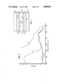
- a radiographic element 100 is positioned between a pair of light emitting intensifying screens 201 and 202.
- the radiographic element support is comprised of a radiographic support element 101, typically transparent or blue tinted, capable of transmitting at least a portion of the light to which it is exposed and optional, similarly transmissive under layer units 103 and 105.
- On the first and second opposed major faces 107 and 109 of the support formed by the under layer units are crossover reducing hydrophilic colloid layers 111 and 113, respectively. Overlying the crossover reducing layers 111 and 113 are light recording latent image forming silver halide emulsion layer units 115 and 117, respectively.
- Each of the emulsion layer units is formed of one or more hydrophilic colloid layers including at least one silver halide emulsion layer. Overlying the emulsion layer units 115 and 117 are optional hydrophilic colloid protective overcoat layers 119 and 121, respectively. All of the hydrophilic colloid layers are permeable to processing solutions.
- the assembly is imagewise exposed to X radiation.
- the X radiation is principally absorbed by the intensifying screens 201 and 202, which promptly emit light as a direct function of X ray exposure.
- the intensifying screens 201 and 202 which promptly emit light as a direct function of X ray exposure.
- the light recording latent image forming emulsion layer unit 115 is positioned adjacent this screen to receive the light which it emits. Because of the proximity of the screen 201 to the emulsion layer unit 115 only minimal light scattering occurs before latent image forming absorption occurs in this layer unit. Hence light emission from screen 201 forms a sharp image in emulsion layer unit 115.
- crossover reducing layers 111 and 113 are interposed between the screen 201 and the remote emulsion layer unit and are capable of intercepting and attenuating this remaining light. Both of these layers thereby contribute to reducing crossover exposure of emulsion layer unit 117 by the screen 201.
- the screen 202 produces a sharp image in emulsion layer unit 117, and the light absorbing layers 111 and 113 similarly reduce crossover exposure of the emulsion layer unit 115 by the screen 202.
- the radiographic element 100 is removed from associated with the intensifying screens 210 and 202 and processed in a rapid access processor--that is, a processor, such as an RP-X-Omat® processor, which is capable of producing a image bearing radiographic element dry to the touch in less than 90 seconds.
- Rapid access processors are illustrated by Barnes et al U.S. Pat. No. 3,545,971 and Akio et al published European patent application No. 0,248,390.
- radiographic elements satisfying the requirements of the present invention are specifically identified as being those that are capable of emerging dry to the touch when processed in 90 seconds according to the following reference conditions:
- the development step employs the following developer:
- the fixing step employs the following fixing composition:
- the radiographic elements of the present invention make possible the unique combination of advantages set forth above by employing (1) substantially optimally spectrally sensitized tabular grain emulsions in the emulsion layer units to reach low crossover levels while achieving the high covering power and other known advantages of tabular grain emulsions, (2) one or more particulate dyes in the interlayer units to further reduce crossover to less than 10 percent without emulsion desensitization and minimal or no residual dye stain, and (3) hydrophilic colloid swell and coverage levels compatible with obtaining uniform coatings, rapid access processing, and reduced or eliminated wet pressure sensitivity.
- Each under layer unit contains a processing solution hydrophilic colloid and a particulate dye.
- the total concentration of the microcrystalline dye in both under layer units is sufficient to reduce the crossover of the radiographic element below 10 percent. This can be achieved when the concentration of the dye is chosen to impart to the structure separating the emulsion layer units an optical density of at least 2.00 at the peak wavelength of emulsion sensitivity.
- the dye can be unequally distributed between the two under layer units, it is preferred that each under layer unit contain sufficient dye to raise the optical density of that under layer unit to 1.00.
- the dye since it is conventional practice to employ intensifying screen-radiographic element combinations in which the peak emulsion sensitivity matches the peak light emission by the intensifying screens, it follows that the dye also exhibits a density of at least 1.00 at the wavelength of peak emission of the intensifying screen. Since neither screen emissions nor emulsion sensitivities are confined to a single wavelength, it is preferred to choose particulate dyes, including combinations of particulate dyes, capable of imparting a density of 1.00 or more over the entire spectral region of significant sensitivity and emission.
- the particulate dye be selected to produce an optical density of at least 1.00 over the entire spectral region of 400 to 500 nm.
- the particulate dye exhibit a density of at least 1.00 over the spectral region of 450 to 550 nm.
- particulate dye optical densities of 1.00 are effective to reduce crossover to less than 10 percent
- particulate dye densities can be increased until radiographic element crossover is effectively eliminated. For example, by increasing the particulate dye concentration so that it imparts a density of 2.0 to the radiographic element, crossover is reduced to only 1 percent.
- the size of the dye particles is chosen to facilitate coating and rapid decolorization of the dye. In general smaller dye particles lend themselves to more uniform coatings and more rapid decolorization.
- the dye particles employed in all instances have a mean diameter of less than 10.0 ⁇ m and preferably less than 1.0 ⁇ m. There is no theoretical limit on the minimum sizes the dye particles can take.
- the dye particles can be most conveniently formed by crystallization from solution in sizes ranging down to about 0.01 ⁇ m or less. Where the dyes are initially crystallized in the form of particles larger than desired for use, conventional techniques for achieving smaller particle sizes can be employed, such as ball milling, roller milling, sand milling, and the like.
- hydrophilic colloid layers are most commonly gelatin and gelatin derivatives (e.g., acetylated or phthalated gelatin).
- the hydrophilic colloid must be coated at a layer coverage of at least 10 mg/dm 2 . Any convenient higher coating coverage can be employed, provided the total hydrophilic colloid coverage per side of the radiographic element does not exceed that compatible with rapid access processing.
- Hydrophilic colloids are typically coated as aqueous solutions in the pH range of from about 5 to 6, most typically from 5.5 to 6.0, to form radiographic element layers.
- the dyes which are selected for use in the practice of this invention are those which are capable of remaining in particulate form at those pH levels in aqueous solutions.
- Dyes which by reason of their chromophoric make up are inherently ionic, such as cyanine dyes, as well as dyes which contain substituents which are ionically dissociated in the above-noted pH ranges of coating may in individual instances be sufficiently insoluble to satisfy the requirements of this invention, but do not in general constitute preferred classes of dyes for use in the practice of the invention.
- dyes with sulfonic acid substituents are normally too soluble to satisfy the requirements of the invention.
- nonionic dyes with carboxylic acid groups (depending in some instances on the specific substitution location of the carboxylic acid group) are in general insoluble under aqueous acid coating conditions. Specific dye selections can be made from known dye characteristics or by observing solubilities in the pH range of from 5.5 to 6.0 at normal layer coating temperatures--e.g., at a reference temperature of 40° C.
- Preferred particulate dyes are nonionic polymethine dyes, which include the merocyanine, oxonol, hemioxonol, styryl, and arylidene dyes.
- the merocyanine dyes include, joined by a methine linkage, at least one specific heterocyclic nucleus and at least one acidic nucleus.
- the nuclei can be joined by an even number or methine groups or in so-called "zero methine" merocyanine dyes, the methine linkage takes the form of a double bond between methine groups incorporated in the nuclei.
- Basic nuclei such as azolium or azinium nuclei, for example, include those derived from pyridinium, quinolinium, isoquinolinium, oxazolium, pyrazolium, pyrrolium, indolium, oxadiazolium, 3H--or 1H-benzoindolium, pyrrolopyridinium, phenanthrothiazolium, and acenaphthothiazolium quaternary salts.
- Z 3 represents the elements needed to complete a cyclic nucleus derived from basic heterocyclic nitrogen compounds such as oxazoline, oxazole, benzoxazole, the naphthoxazoles (e.g., naphth[2,1-d]oxazole, naphth[2,3-d]oxazole, and naphth[1,2-d]oxazole), oxadiazole, 2- or 4-pyridine, 2- or 4-quinoline, 1- or 3-isoquinoline, benzoquinoline, 1H- or 3H-benzoindole, and pyrazole, which nuclei may be substituted on the ring by one or more of a wide variety of substituents such as hydroxy, the halogens (e.g., fluoro, chloro, bromo, and iodo), alkyl groups or substituted alkyl groups (e.g., methyl, ethyl, propyl, isopropyl, butyl, o
- Q' represents the elements needed to complete a cyclic nucleus derived from basic heterocyclic nitrogen compounds such as pyrrole, pyrazole, indazole, and pyrrolopyridine;
- R represents alkyl groups, aryl groups, alkenyl groups, or aralkyl groups, with or without substituents, (e.g., carboxy, hydroxy, sulfo, alkoxy, sulfato, thiosulfato, phosphono, chloro, and bromo substituents);
- L is in each occurrence independently selected to represent a substituted or unsubstituted methine group--e.g., --CR 8 ⁇ groups, where R 8 represents hydrogen when the methine group is unsubstituted and most commonly represents alkyl of from 1 to 4 carbon atoms or phenyl when the methine groups is substituted; and
- q 0 or 1.
- Merocyanine dyes link one of the basic heterocyclic nuclei described above to an acidic keto methylene nucleus through a methine linkage, where the methine groups can take the form --CR 8 ⁇ described above.
- Merocyanine dyes link one of the basic heterocyclic nuclei described above to an acidic keto methylene nucleus through a methine linkage as described above.
- Exemplary acidic nuclei are those which satisfy Formula III. ##STR2## where
- G 1 represents an alkyl group or substituted alkyl group, an aryl or substituted aryl group, an aralkyl group, an alkoxy group, an aryloxy group, a hydroxy group, an amino group, or a substituted amino group, wherein exemplary substituents can take the various forms noted in connection with Formulae VI and VII;
- G 2 can represent any one of the groups listed for G 1 and in addition can represent a cyano group, an alkyl, or arylsulfonyl group, or a group represented by ##STR3## or G 2 taken together with G 1 can represent the elements needed to complete a cyclic acidic nucleus such as those derived from 2,4-oxazolidinone (e.g., 3-ethyl-2,4-oxazolidindione), 2,4-thiazolidindione (e.g., 3-methyl-2,4-thiazolidindione), 2-thio-2,4-oxazolidindione (e.g., 3-phenyl-2-thio-2,4-oxazolidindione), rhodanine, such as 3-ethylrhodanine, 3-phenylrhodanine, 3-(3-dimethylaminopropyl)rhodanine, and 3-carboxymethylrhodanine, hydantoin (e.g., 1,
- Useful hemioxonol dyes exhibit a keto methylene nucleus as shown in Formula III and a nucleus as shown in Formula IV. ##STR4## where
- G 3 and G 4 may be the same or different and may represent alkyl, substituted alkyl, aryl, substituted aryl, or aralkyl, as illustrated for R ring substituents in Formula I or G 3 and G 4 taken together complete a ring system derived from a cyclic secondary amine, such as pyrrolidine, 3-pyrroline, piperidine, piperazine (e.g., 4-methylpiperazine and 4-phenylpiperazine), morpholine, 1,2,3,4-tetrahydroquinoline, decahydroquinoline, 3-azabicyclo[3,2,2]nonane, indoline, azetidine, and hexahydroazepine.
- a cyclic secondary amine such as pyrrolidine, 3-pyrroline, piperidine, piperazine (e.g., 4-methylpiperazine and 4-phenylpiperazine), morpholine, 1,2,3,4-tetrahydroquinoline, decahydroquinoline
- Exemplary oxonol dyes exhibit two keto methylene nuclei as shown in Formula III joined through one or higher uneven number of methine groups.
- Useful arylidene dyes exhibit a keto methylene nucleus as shown in Formula III and a nucleus as shown in Formula V joined by a methine linkage as described above containing one or a higher uneven number of methine groups.
- G 3 and G 4 are as previously defined.
- a specifically preferred class of oxonol dyes for use in the practice of the invention are the oxonol dyes disclosed in Factor and Diehl U.S. Ser. No. 73,257, filed July 13, 1987, commonly assigned, cited above. These oxonol dyes satisfy Formula VI. ##STR6## wherein
- R 1 and R 2 each independently represent alkyl of from 1 to 5 carbon atoms.
- arylidene dyes for use in the practice of the invention are the arylidene dyes disclosed in Diehl and Factor U.S. Ser. Nos. 945,634, and 137,490 refiled as 373,747, commonly assigned, cited above. These arylidene dyes satisfy Formula VII. ##STR7##
- A represents a substituted or unsubstituted acidic nucleus having a carboxyphenyl or sulfonamidophenyl substituent selected from the group consisting of 2-pyrazolin-5-ones free of any substituent bonded thereto through a carboxyl group, rhodanines; hydantoins; 2-thiohydantoins; 4-thiohydantoins; 2,4-oxazolidindiones; 2-thio-2,4-oxazolidindiones; isoxazolinones; barbiturics; 2-thiobarbiturics and indandiones;
- R represents hydrogen, alkyl of 1 to 4 carbon atoms or benzyl
- R 1 and R 2 each independently, represents alkyl or aryl; or taken together with R 5 , R 6 , N, and the carbon atoms to which they are attached represent the atoms needed to complete a julolidene ring;
- R 3 represents H, alkyl or aryl
- R 5 and R 6 each independently, represents H or R 5 taken together with R 1 ; or R 6 taken together with R 2 each may represent the atoms necessary to complete a 5 or 6 membered ring;
- m 0 or 1.
- R 1 and R 2 are each independently substituted or unsubstituted alkyl or substituted or unsubstituted aryl, or together represent the atoms necessary to complete a substituted or unsubstituted 5- or 6-membered ring.
- R 3 and R 4 each independently represents H, substituted or unsubstituted alkyl, substituted or unsubstituted aryl, CO 2 H, or NHSO 2 R 6 .
- R 5 is H, substituted or unsubstituted alkyl, substituted or unsubstituted aryl, carboxylate (i.e., COOR where R is substituted or unsubstituted alkyl), or substituted or unsubstituted acyl
- R 6 and R 7 are each independently substituted or unsubstituted alkyl or substituted or unsubstituted aryl, and n is 1 or 2.
- R 8 is either substituted or unsubstituted alkyl, or is part of a double bond between the ring carbon atoms to which R 1 and R 2 are attached. At least one of the aryl rings of the dye molecule must have at least one substituent that is CO 2 H or NHSO 2 R 6 .
- Oxazole and oxazoline benzoylacetonitrile merocyanine particulate dyes of the type disclosed by Factor and Diehl U.S. Ser. No. 137,491 (refiled as 290,602), commonly assigned, cited above, are also contemplated. These particulate dyes can be represented by Formula IX. ##STR9##
- R 1 , R 2 , R 3 , R 4 , R 5 , and R 6 may be substituted or unsubstituted alkyl or substituted or unsubstituted aryl, preferably substituted or unsubstituted alkyl of 1 to 6 carbon atoms or substituted or unsubstituted aryl of 6 to 12 carbon atoms.
- R 7 may be substituted or unsubstituted alkyl of from 1 to 6 carbon atoms.
- alkyl or aryl groups may be substituted with any of a number of substituents as is known in the art, other than those, such as sulfo substituents, that would tend to increase the solubility of the dye so much as to cause it to become soluble at coating pH's.
- substituents include halogen, alkoxy, ester groups, amido, acyl, and alkylamino.
- alkyl groups include methyl, ethyl, n-propyl, isopropyl, n-butyl, isobutyl, n-pentyl, n-hexyl, or isohexyl.
- aryl groups include phenyl, naphthyl, anthracenyl, pyridyl, and styryl.
- R 1 and R 2 may also together represent the atoms necessary to complete a substituted or unsubstituted 5- or 6-membered ring, such as phenyl, naphthyl, pyridyl, cyclohexyl, dihydronaphthyl, or acenaphthyl.
- This ring may be substituted with substituents, other than those, such as sulfo substituents, that would tend to increase the solubility of the dye so mush as to cause it to become soluble at coating pH's.
- substituents include halogen, alkyl, alkoxy, ester, amido, acyl, and alkylamino.
- Useful bleachable particulate dyes can be found among a wide range of cyanine, merocyanine, oxonol, arylidene (i.e., merostyryl), anthraquinone, triphenylmethine, azo, azomethine, and other dyes, provided certain criteria are met identified in Diehl and Factor U.S. Ser. No. 137,495 (refiled as 373,749), commonly assigned, cited above. Such dyes satisfy Formula X.
- D is a chromophoric light-absorbing compound, which may or may not comprise an aromatic ring if y is not 0 and which comprises an aromatic ring if y is 0,
- A is an aromatic ring bonded directly or indirectly to D
- X is a substituent, either on A or on an aromatic ring portion of D, with an ionizable proton
- y is 0 to 4
- n is 1 to 7, where the dye is substantially aqueous insoluble at a pH of 6 or below and substantially aqueous soluble at a pH of 8 or above.
- Synthesis of the particulate dyes can be achieved by procedures known in the art for the synthesis of dyes of the same classes. For example, those familiar with techniques for dye synthesis disclosed in "The Cyanine Dyes and Related Compounds", Frances Hamer, Interscience Publishers, 1964, could readily synthesize the cyanine, merocyanine, merostyryl, and other polymethine dyes.
- the oxonol, anthraquinone, triphenylmethane, azo, and azomethine dyes are either known dyes or substituent variants of known dyes of these classes and can be synthesized by known or obvious variants of known synthetic techniques forming dyes of these classes. Specific illustrations of dye preparations are incorporated in the Appendix below.
- particulate bleachable dyes useful in the practice of this invention include the following:
- the dye can be added directly to the hydrophilic colloid as a particulate solid or can be converted to a particulate solid after it is added to the hydrophilic colloid.
- One example of the latter technique is to dissolve a dye which is not water soluble in a solvent which is water soluble.
- the dye solution is mixed with an aqueous hydrophilic colloid, followed by noodling and washing of the hydrophilic colloid (see Research Disclosure, Item 17643, cited above, Section II), the dye solvent is removed, leaving particulate dye dispersed within the hydrophilic colloid.
- any water insoluble dye which that is soluble in a water miscible organic solvent can be employed as a particulate dye in the practice of the invention, provided the dye is susceptible to bleaching under processing conditions--e.g., at alkaline pH levels.
- contemplated water miscible organic solvents are methanol, ethyl acetate, cyclohexanone, methyl ethyl ketone, 2-(2-butoxyethoxy)ethyl acetate, triethyl phosphate, methylacetate, acetone, ethanol, and dimethylformamide.
- Dyes preferred for use with these solvents are sulfonamide substituted arylidene dyes, specifically preferred examples of which are set forth about in Tables IIA and III.
- the dyes employed in the under layer units must be substantially decolorized on processing.
- substantially decolorized is employed to mean that the dye in the under layer units raises the minimum density of the radiographic element when fully processed under the reference processing conditions, stated above, by no more than 0.1, preferably no more than 0.05, within the visible spectrum. As shown in the examples below the preferred particulate dyes produce no significant increase in the optical density of fully processed radiographic elements of the invention.
- UV absorber preferably blended with the dye in each of crossover reducing layers 111 and 113.
- Any conventional UV absorber can be employed for this purpose.
- Illustrative useful UV absorbers are those disclosed in Research Disclosure, Item 18431, cited above, Section V, or Research Disclosure, Item 17643, cited above Section VIII(C), both here incorporated by reference.
- Preferred UV absorbers are those which either exhibit minimal absorption in the visible portion of the spectrum or are decolorized on processing similarly as the crossover reducing dyes.
- At least one additional hydrophilic colloid layer specifically at one halide emulsion layer unit comprised of a spectrally sensitized silver bromide or bromoiodide tabular grain emulsion layer.
- At least 50 percent (preferably at least 70 percent and optimally at least 90 percent) of the total grain projected area of the tabular grain emulsion is accounted for by tabular grains having a thickness less than 0.3 ⁇ m (preferably less than 0.2 ⁇ m) and an average aspect ratio of greater than 5:1 (preferably greater than 8:1 and optimally at least 12:1).
- Preferred tabular grain silver bromide and bromoiodide emulsions are those disclosed by Wilgus et al U.S.
- the tabular grain emulsions are substantially optimally spectrally sensitized. That is, sufficient spectral sensitizing dye is adsorbed to the emulsion grain surfaces to achiever at least 60 percent of the maximum speed attainable from the emulsions under the contemplated conditions of exposure. It is known that optimum spectral sensitization is achieved at about 25 to 100 percent or more of monolayer coverage of the total available surface area presented by the grains.
- the preferred dyes for spectral sensitization are polymethine dyes, such as cyanine, merocyanine, hemicyanine, hemioxonol, and merostyryl dyes. Specific examples of spectral sensitizing dyes and their use to sensitize tabular grain emulsions are provided by Kofron et al U.S. Pat. No. 4,439,520, here incorporated by reference.
- the tabular grain emulsions are rarely put to practical use without chemical sensitization. Any convenient chemical sensitization of the tabular grain emulsions can be undertaken.
- the tabular grain emulsions are preferably substantially optimally (as defined above) chemically and spectrally sensitized.
- Useful chemical sensitizations including noble metal (e.g., gold) and chalcogen (e.g., sulfur and/or selenium) sensitizations as well as selected site epitaxial sensitizations, are disclosed by the patents cited above relating to tabular grain emulsions, particularly Kofron et al and Maskasky.
- the emulsion layers can include as vehicles any one or combination of various conventional hardenable hydrophilic colloids alone or in combination with vehicle extenders, such as latices and the like.
- vehicle extenders such as latices and the like.
- the vehicles and vehicle extenders of the emulsion layer units can be identical to those of the interlayer units.
- the vehicles and vehicle extenders can be selected from among those disclosed by Research Disclosure, Item 17643, cited above, Section IX, here incorporated by reference.
- Specifically preferred hydrophilic colloids are gelatin and gelatin derivatives.
- each emulsion layer unit should contain a silver coverage from about 18 to 30 mg/dm 2 , preferably 21 to 27 mg/dm 2 .
- overcoat layers can be formed of the same vehicles and vehicle extenders disclosed above in connection with the emulsion layers.
- the overcoat layers are most commonly gelatin or a gelatin derivative.
- the total hydrophilic colloid coverage on each major surface of the support must be at least 35 mg/dm 2 . It is an observation of this invention that it is the total hydrophilic colloid coverage on each surface of the support and not, as has been generally believed, simply the hydrophilic colloid coverage in each silver halide emulsion layer that controls its wet pressure sensitivity.
- the emulsion layer can contain as little as 20 mg/dm 2 of hydrophilic colloid.
- the total hydrophilic coating coverage on each major surface of the support must be less than 65 mg/dm 2 , preferably less than 55 mg/dm 2 , and the hydrophilic colloid layers must be substantially fully forehardened.
- substantially fully forehardened it is meant that the processing solution permeable hydrophilic colloid layers are forehardened in an amount sufficient to reduce swelling of these layers to less than 300 percent, percent swelling being determined by the following reference swell determination procedure: (a) incubating said radiographic element at 38° C. for 3 days at 50 percent relative humidity, (b) measuring layer thickness, (c) immersing said radiographic element in distilled water at 21° C.
- step (b) determining the percent change in layer thickness as compared to the layer thickness measured in step (b).
- This reference procedure for measuring forehardening is disclosed by Dickerson U.S. Pat. No. 4,414,304. Employing this reference procedure, it is preferred that the hydrophilic colloid layers be sufficiently forehardened that swelling is reduced to less than 200 percent under the stated test conditions.
- Transparent film supports such as any of those disclosed in Research Disclosure, Item 17643, cited above, Section XIV, are all contemplated. Due to their superior dimensional stability the transparent film supports preferred are polyester supports. Poly(ethylene terephthalate) is a specifically preferred polyester film support. The support is typically tinted blue to aid in the examination of image patterns. Blue anthracene dyes are typically employed for this purpose. In addition to the film itself, the support is usually formed with a subbing layer on the major surface intended to receive the under layer units. For further details of support construction, including exemplary incorporated anthracene dyes and subbing layers, refer to Research Disclosure, Item 18431, cited above, Section XII.
- the radiographic elements can and in most practical applications will contain additional conventional features.
- the emulsion layer units can contain stabilizers, antifoggants, and antikinking agents of the type set forth in Section II, and the overcoat layers can contain any of variety of conventional addenda of the type set forth in Section IV.
- the outermost layers of the radiographic element can also contain matting agents of the type set out in Research Disclosure, Item 17643, cited above, Section XVI. Referring further to Research Disclosure, Item 17643, incorporation of the coating aids of Section XI, the plasticizers and lubricants of Section XII, and the antistatic layers of Section XIII, are each contemplated.
- the following examples compare the performance of dual coated radiographic elements exposed using blue emitting thulium activated lanthanum oxybromide phosphor intensifying screens.
- the radiographic elements were identical, except for the choice of the crossover reducing materials employed between the emulsion layer and the support on each major surface.
- the crossover reducing dye satisfying the requirements of the invention was yellow Dye 56 shown above in Table VIII.
- the dye was employed in a particulate form, the mean diameter of the dye particles being 0.8 ⁇ m.
- C-1 Tartrazine Yellow
- M-1 cationic mordant poly(1-methyl-2-vinylpyridinium p-toluene sulfonate
- CLS Carey Lea Silver
- One control element was constructed with the same hydrophilic colloid layers, but without a crossover reducing material being present. This element is referred to as C--O.
- An emulsion layer was coated over each hydrophilic colloid layer at a coverage of 22 mg/dm 2 silver and 22 mg/dm 2 gelatin.
- the emulsion was a high aspect ratio tabular grain silver bromide emulsion having a mean grain diameter of 1.8 ⁇ m.
- Tabular grains having a thickness of 0.16 ⁇ m and a mean diameter of at least 0.6 ⁇ m exhibited an average aspect ratio of 11.25:1 and accounted for greater than 70 percent of the total grain projected area.
- hydrophilic colloid layers (including the emulsion layers) were hardened with bis(vinylsulfonylmethyl) ether at 1.0% of the gelatin weight.
- samples of the dual coated radiographic elements were exposed with a single intensifying screen placed in contact with one emulsion layer. Black paper was placed against the other emulsion side of the sample.
- the X-radiation source was a Picker VTX653 3-phase X-ray machine, with a Dunlee High-Speed PX1431-CQ-150 kVp 0.7/1.4 mm focus tube.
- Exposure was made at 70 kVp, 32mAs, at a distance of 1.40 m. Filtration was with 3 mm Al equivalent (1.25 inherent+1.75 al); Half Value Layer (HVL)-2.6 mm Al. A 26 step Al wedge was used, differing in thickness by 2 mm per step.
- Relative speed reported in Table XII is the speed of the emulsion layer nearest the support.
- Dye 56 was entirely decolorized during processing. From FIG. 2 it can be seen that the density of the element after processing was essentially similar to the element lacking a crossover reducing material. At the same time the capability of crossover reduction below 10 percent was demonstrated. Some loss of photographic speed was observed, but it is to be noted that, since the purpose of a crossover reducing agent is to prevent a portion of the light emitted by the screens from exposing the emulsion layers, some reduction in photographic speed is inherent in crossover reduction.
- This example demonstrates the satisfactory performance of a bleachable particulate dye to reduce crossover without producing dye stain in the processed radiographic element and with only minimal impact on imaging speed.
- the control crossover reducing materials were unacceptable because of their high dye stain, and the control dye was unacceptable in producing an increased loss in imaging speed.
- Examples 1 through 6 The procedure of Examples 1 through 6 was repeated, except that magenta dyes were substituted for testing; the emulsion layer was substantially optimally spectrally sensitized with 400 mg/Ag mole of the green spectral sensitizing dye anhydro-5,5'-di-chloro-9-ethyl-3,3'-di(3-sulfopropyl)oxacarbocyanine hydroxide, sodium salt; and green emitting intensifying screens, Kodak Lanex Regular® screens, were employed.
- the dye satisfying the requirements of the invention was magenta Dye 59 shown above in Table VIII.
- the dye was employed in a particulate form, the mean diameter of the dye particles being 0.2 ⁇ m.
- Acid Magenta (C.I. Acid Violet 19-C.I. 42,685), hereinafter referred to as C-2, was selected as a control exemplary of dyes which are water soluble and bleachable taught by the art to be used as a crossover reducing dye in a double coated radiographic element.
- C-2 Acid Magenta
- M-1 cationic mordant M-1 was employed in a 5 parts mordant to 1 part dye weight ratio.
- C-3 1,3-Bis[1-(4-sulfonylphenyl)-3-carboxy-2-pyraxolin-5-one-4] trimethine oxonol, disodium salt, hereinafter referred to as C-3, was selected as a control exemplary of magenta dyes which are water soluble and nonbleachable.
- Dye C-3 differed from dye 10 disclosed on page 5 of U.K. Pat. Spec. 1,414,456 only in that the nuclei were joined by 3 methine groups instead of 5 (to shift absorption into the desired green spectral region). To reduce wandering of the dye cationic mordant M-1 was again employed in a 5 parts mordant to 1 part dye weight ratio.
- the under layer contained a gelatin coating coverage of 16.1 mg/dm 2 and a gelatin overcoat layer gelatin coverage 6.7 mg/dm 2 , with the emulsion layer gelatin content being varied to obtain the total gelatin per side coating coverage given.
- the under coat layer contained in addition to the gelatin a combination of yellow and magenta particulate dyes Dye 56 and Dye 59, each at a coating coverage of 1.6 mg/dm 2 .
- the hardener bis(vinylsulfonylmethyl)ether (BVSME) was employed in the percent by weight, based on total gelatin, indicated. The results are summarized in Table XIV.
- Table XIV also demonstrates the maintenance of covering power levels by the tabular grain emulsions with progressively higher levels of hardening. Covering power is reported as 100 times the ratio of maximum density to developed silver, expressed in grams per square decimeter.
- a series of radiographic elements were prepared similarly as in Examples 13-19, except that percent of BVSME hardener was held constant at 1 percent by weight and the hydrophilic colloid coverage in the under layer (UL) and the emulsion layer (EL) on each side of the support was varied. In some coatings the under layer was omitted entirely. These elements were, of course, unacceptable for lacking the particulate dye required for crossover reduction. The overcoat layer gelatin coating coverage remained constant at 6.7 mg/dm 2 .
- wet pressure sensitivity is reported as a ranking, with the ranking of 1 indicating no observable increase in graininess of the fully processed element and the ranking of 5 indicating the greatest manifestation of graininess.
- the ranking level of 5 the user would find the graininess clearly objectionable.
- the ranking level of 4 the user would readily notice the graininess.
- radiographic elements exhibiting wet pressure sensitivity levels of 4 or 5 would in most instances be considered below marketable quality.
- the radiographic elements were considered to be marginally acceptable.
- the ranking level of 2 probably only one looking for a graininess deficiency in the radiographic image would be aware of it.
- the wet pressure sensitivity ranking increased from 4 to 3--that is, from unacceptable wet pressure sensitivity to marginally acceptable wet pressure sensitivity.
- the reaction was repeated twice more to obtain a total of 3.0 g of crude dye, which was dissolved in 250 ml hot acetone, which was stirred with 10 g Amberlyst-15® ion exchange resin for 3 hours, heated for 15 minutes to reflux, then filtered while hot. The filtrate was chilled to 2° C. overnight and the resulting yellow precipitate was air dried to yield 2.3 g of Dye 6.
- the pKa's of this dye was measured by acid titration in a 50/50 (volume basis) mixture of ethanol and water and was determined to be 8.1 for the methylsulfonamido substituent and 9.2 for the hexylsulfonamido substituent.
- the log P was determined to be 4.66.
- the solid was recrystallized by dissolving in 75 ml hot chclohexanone, diluting with 200 ml isopropyl alcohol, stored overnight at 2° C., and the solid filtered out, washed with diethyl ether and air dried to yield 2.4 g of Dye 7.
- the pKa's were measured by acid titration in a 50/50 (volume basis) mixture of ethanol and water and determined to be 8.2 for the propylsulfonamido substituent and 9.2 for the lmethjylsulfonamido.
- the log P was determined to be 3.07.
- the dye was recrystallized by slurrying in 30 ml of a 2:1 mixture of ethanol and methanol, heating, chilling with ice, filtering the solid, and washing with ethanol to yield 0.80 g of dye 18.
- the NMR and IR spectra were consistent with the structure assigned.
- the C, H, and N elemental analyses were in agreement with those calculated for the empirical formula.
- the pKa of the carboxy substituent was measured by acid titration in a 50/50 volume basis mixture of ethanol and water and determined to be 5.
- the precipitate containing the dye was then purified through a number of washing and dissolution/recrystallization steps.
- the precipitate was first slurried in 500 ml refluxing glacial acetic acid, cooled to room temperature, filtered, washed with 250 ml acetic acid, 250 ml H 2 O, 250 ml methanol, and then dried. It was then dissolved in 100 ml hot dimethylsulfoxide and cooled to 40° C. 300 ml methanol was added, upon which a red precipitate formed, which was filtered, washed with methanol, acetone, and ligroin, and dried.
- This precipitate was dissolved in 200 ml methanol and 6 ml (4.38 g) triethylamine and heated to reflux. 4.8 ml of concentrated hydrochloric acid was added and a fine red precipitate was formed. The solution was filtered while hot and the precipitate was washed with methanol and acetone and dried. The precipitate was then dissolved in a refluxing mixture of 200 ml ethanol and 6.0 ml (4.38 g) triethylamine. 9.0 g of sodium iodide dissolved in 50 ml methanol was added. Upon cooling to room temperature, a red precipitate formed. The mixture was chilled in ice for one hour, then filtered. The precipitate was washed with ethanol, ligroin and dried to yield the sodium salt of the dye.
- the sodium salt of the dye was dissolved in 200 ml water with rapid stirring. 6.0 ml concentrated hydrochloric acid was added and a fluffy red precipitate formed. The mixture was filtered and the precipitate was washed with water, methanol, acetone, and ligroin, and dried to yield Dye 125.
Abstract
Description
______________________________________
development      24 seconds at 40° C.,
fixing           20 seconds at 40° C.,
washing          10 seconds at 40° C., and
drying           20 seconds at 65° C.,
______________________________________
______________________________________
Hydroquinone             30 g
1-Phenyl-3-pyrazolidone  1.5 g
KOH                      21 g
NaHCO.sub.3              7.5 g
K.sub.2 SO.sub.3         44.2 g
Na.sub.2 S.sub.2 O.sub.5 12.6 g
NaBr                     35 g
5-Methylbenzotriazole    0.06 g
Glutaraldehyde           4.9 g
Water to 1 liter at pH 10.0, and
______________________________________
______________________________________
Ammonium thiosulfate, 60%
                        260.0  g
Sodium bisulfite        180.0  g
Boric acid              25.0   g
Acetic acid             10.0   g
Aluminum sulfate        8.0    g
Water to 1 liter at pH 3.9 to
                        4.5.
______________________________________
______________________________________
development      20 seconds at 40° C.,
fixing           12 seconds at 40° C.,
washing          8 seconds at 40° C., and
drying           20 seconds at 65° C.,
______________________________________
______________________________________
Hydroquinone             30 g
1-Phenyl-3-pyrazolidone  1.5 g
KOH                      21 g
NaHCO.sub.3              7.5 g
K.sub.2 SO.sub.3         44.2 g
Na.sub.2 S.sub.2 O.sub.5 12.6 g
NaBr                     35 g
5-Methylbenzotriazole    0.06 g
Glutaraldehyde           4.9 g
Water to 1 liter at pH 10.0, and
______________________________________
______________________________________
Ammonium thiosulfate, 60%
                        260.0  g
Sodium bisulfite        180.0  g
Boric acid              25.0   g
Acetic acid             10.0   g
Aluminum sulfate        8.0    g
Water to 1 liter at pH 3.9 to
                        4.5.
______________________________________
[D-(A).sub.y ]--X.sub.n (X)
                                  TABLE I
__________________________________________________________________________
Trimethine Pyrazolone Cinnamylidene Dyes
General Structure:
 ##STR10##
                       λ-max
                             ε-max (× 10.sup.4)
Dye R.sup.1
           R.sup.2
                 R.sup.3
                       (methanol)
__________________________________________________________________________
1   CH.sub.3
           H     CO.sub.2 H
                       516   4.62
2   CH.sub.3 CO
           H     CO.sub.2 H
                       573   5.56
3   CO.sub.2 Et
           H     CO.sub.2 H
                       576   5.76
4   CH.sub.3
           CO.sub.2 H
                 H     506   3.90
5   CO.sub.2 Et
           CO.sub.2 H
                 H     560   5.25
__________________________________________________________________________
                                  TABLE II
__________________________________________________________________________
Benzoylacetonitrile Merocyanine Dyes
General Structure:
 ##STR11##
                      λ-max
                            ε-max (× 10.sup.4)
Dye  R.sup.1   R.sup.2
                      (methanol)
__________________________________________________________________________
6    n-C.sub.6 H.sub.13 SO.sub.2 NH
               CH.sub.3
                      445   7.32
7    CH.sub.3 SO.sub.2 NH
               C.sub.3 H.sub.7
                      446   7.86
8    CH.sub.3 SO.sub.2 NH
               n-C.sub.6 H.sub.13
                      447   7.6
9    H         CH.sub.3
                      449   6.5
__________________________________________________________________________
                                  TABLE II-A
__________________________________________________________________________
Arylidene Dyes
General Structure:
 ##STR12##
                 λ-max
                           ε-max (× 10.sup.4)
Dye     R        (methanol)
__________________________________________________________________________
10      H        424       3.98
11      CH.sub.3 423       3.86
__________________________________________________________________________
                                  TABLE III
__________________________________________________________________________
Benzoylacetonitrile Arylidene Dyes
General Structure:
 ##STR13##
                         λ-max
                              ε-max (× 10.sup.4)
Dye
   R.sup.1 R.sup.2   R.sup.3
                         (methanol)
__________________________________________________________________________
12 i-PrO.sub.2 CCH.sub.2
           i-PrO.sub.2 CCH.sub.2
                     C.sub.3 H.sub.7
                         426  3.5
13 C.sub.2 H.sub.5
           CF.sub.3 CH.sub.2 O.sub.2 CCH.sub.2
                     CH.sub.3
                         439  4.27
14 i-PrO.sub.2 CCH.sub.2
           i-PrO.sub.2 CCH.sub.3
                     CH.sub.3
                         420  4.2
15 C.sub.2 H.sub.5
           CF.sub.3 CH.sub.2 O.sub.2 CCH.sub.2
                     C.sub.3 H.sub.7
                         430  4.25
__________________________________________________________________________
                                  TABLE IV
__________________________________________________________________________
Pyrazolone Merocyanines Dyes
General Structure:
 ##STR14##
                         λ-max
                              εmax (× 10.sup.4)
Dye  R.sup.1
          R.sup.2
               R.sup.3
                    R.sup.4
                         (methanol)
__________________________________________________________________________
16   C.sub.2 H.sub.5
          CH.sub.3
               H    CO.sub.2 H
                         450  7.4
17   C.sub.2 H.sub.5
          CH.sub.3
               CO.sub.2 H
                    H    452  7.19
18
      ##STR15##
λ-max 562 nm
                  ε-max = 11.9 × 10.sup.4
(methanol)
__________________________________________________________________________
              TABLE V
______________________________________
Barbituric Acid Merocyanines Dyes
General Structure:
 ##STR16##
                λ-max
                       ε-max (× 10.sup.4)
Dye  R.sup.1    R.sup.2
                       R.sup.3
                            (methanol)
______________________________________
19   CH.sub.2 PhCO.sub.2 H
                C.sub.2 H.sub.5
                       C.sub.2 H.sub.5
                            442    10.70
______________________________________
              TABLE VI
______________________________________
Benzoxazole Benzoylacetonitrile Merocyanine Dyes
General Structure:
 ##STR17##
Dye  R.sup.1        R.sup.2     R.sup.3
______________________________________
20   --             Et          MeOEtSO.sub.2 NH
21   --             Me          MeSO.sub.2 NH
22   MeOEtSO.sub.2 NH
                    Et          MeOEtSO.sub.2 NH
23   MeOEtSO.sub.2 NH
                    Et          HexSO.sub.2 NH
24   MeSO.sub.2 NH  MeOEt       MeSO.sub.2 NH
25   --             CH.sub.2 PhCO.sub.2 H
                                PrSO.sub.2 NH
26   MeSO.sub.2 NH  MeOEt       PrSO.sub.2 NH
27   MeOEtSO.sub.2 NH
                    MeOEt       PrSO.sub.2 NH
28   EtSO.sub.2 NH  Et          MeSO.sub.2 NH
29   EtSO.sub.2 NH  Me          MeSO.sub.2 NH
30   MeOEtSO.sub.2 NH
                    MeOEt       MeOEtSO.sub.2 NH
31   HexSO.sub.2 NH MeOEt       MeSO.sub.2 NH
32   MeOEtSO.sub.2 NH
                    MeOEt       HexSO.sub.2 NH
33   --             CH.sub.2 PhCO.sub.2 H
                                MeSO.sub.2 NH
34   MeSO.sub.2 NH  Me          MeSO.sub.2 NH
35   CO.sub.2 H     Me          MeSO.sub.2 NH
36   CO.sub.2 H     Me          PrSO.sub.2 NH
37   EtOEtOEtSO.sub.2 NH
                    Et          MeSO.sub.2 NH
38   EtOEtOEtSO.sub.2 NH
                    Et          PrSO.sub.2 NH
39   PrSO.sub.2 NH  Et          MeSO.sub.2 NH
40   PrSO.sub.2 NH  Me          MeSO.sub.2 NH
41   MeSO.sub.2 NH  Et          EtSO.sub.2 NH
42   EtSO.sub.2 NH  Et          EtSO.sub.2 NH
43   BuSO.sub.2 NH  Et          MeSO.sub.2 NH
44   BuSO.sub.2 NH  Et          CO.sub.2 H
45   BuSO.sub.2 NH  Me          MeSO.sub.2 NH
46   MeSO.sub.2 NH  Et          BuSO.sub.2 NH
______________________________________
                                  TABLE VII
__________________________________________________________________________
Dye
   Miscellaneous Dyes
__________________________________________________________________________
47
    ##STR18##
   λ-max = 502 nm
   ε-max = 5.47 × 10.sup.4
48
    ##STR19##
49
    ##STR20##
50
    ##STR21##
51
    ##STR22##
52
    ##STR23##
53
    ##STR24##
54
    ##STR25##
55
    ##STR26##
   λ-max = 500 nm
   ε-max = 5.82 × 10.sup.4
__________________________________________________________________________
                                  TABLE VIII
__________________________________________________________________________
Arylidene Dyes
General Structure:
 ##STR27##
                      1-Ph
                      Substn. ×
                               λ-max
                                   ε-max
Dye
   R.sup.1, R.sup.2
            R.sup.3
               R.sup.4
                      Position
                             n (nm)
                                   (10).sup.4
__________________________________________________________________________
56 CH.sub.3 H  CH.sub.3
                      1 4    0 466 3.73
57 C.sub.2 H.sub.5
            H  CH.sub.3
                      1 4    0 471 4.75
58 n-C.sub.4 H.sub.9
            H  CH.sub.3
                      1 4    0 475 4.50
59 CH.sub.3 H  COOC.sub.2 H.sub.5
                      1 4    0 508 5.20
60
    ##STR28##
            CH.sub.3
               CH.sub.3
                      1 4    0 430 3.34
61 CH.sub.3 H  CH.sub.3
                      2 3,5  0 457 3.78
62 C.sub.2 H.sub.5
            H  CH.sub.3
                      2 3,5  0 475 4.55
63 n-C.sub.4 H.sub.9
            H  CH.sub.3
                      2 3,5  0 477 4.92
64
    ##STR29##
            H  CH.sub.3
                      2 3,5  0 420 3.62
65
    ##STR30##
            CH.sub.3
               CH.sub.3
                      2 3,5  0 434 3.25
66  .sub.-i-C.sub.3 H.sub.7 OCCH.sub.2
            H  CH.sub.3
                      1 4    0 420 3.94
67 CH.sub.3 H
                ##STR31##
                      1 4    1 573 5.56
68 CH.sub.3 H  COOEt  1 3,5  0 502 4.83
69 C.sub.2 H.sub.5
            H  COOEt  1 4    0 512 6.22
70 CH.sub.3 H  CF.sub.3
                      1 4    0 507 4.58
71 CH.sub.3 H  Ph     1 4    0 477 4.54
72 CH.sub.3 H
                ##STR32##
                      1 4    0 506 5.36
__________________________________________________________________________
                                  TABLE IX
__________________________________________________________________________
Oxazole and Oxazoline Pyrazolone Merocyanine Dyes
__________________________________________________________________________
73
    ##STR33##
74
    ##STR34##
75
    ##STR35##
76
    ##STR36##
77
    ##STR37##
78
    ##STR38##
79
    ##STR39##
80
    ##STR40##
81
    ##STR41##
82
    ##STR42##
83
    ##STR43##
84
    ##STR44##
85
    ##STR45##
86
    ##STR46##
87
    ##STR47##
88
    ##STR48##
89
    ##STR49##
90
    ##STR50##
91
    ##STR51##
92
    ##STR52##
93
    ##STR53##
94
    ##STR54##
95
    ##STR55##
96
    ##STR56##
97
    ##STR57##
98
    ##STR58##
99
    ##STR59##
__________________________________________________________________________
                                  TABLE X
__________________________________________________________________________
Oxazole and Oxazoline Benzoylacetonitrile
Merocyanine Dyes
__________________________________________________________________________
100
    ##STR60##
101
    ##STR61##
102
    ##STR62##
103
    ##STR63##
104
    ##STR64##
105
    ##STR65##
106
    ##STR66##
107
    ##STR67##
108
    ##STR68##
109
    ##STR69##
110
    ##STR70##
111
    ##STR71##
112
    ##STR72##
113
    ##STR73##
114
    ##STR74##
115
    ##STR75##
116
    ##STR76##
117
    ##STR77##
118
    ##STR78##
119
    ##STR79##
120
    ##STR80##
121
    ##STR81##
122
    ##STR82##
123
    ##STR83##
124
    ##STR84##
__________________________________________________________________________
                                  TABLE XI
__________________________________________________________________________
Oxonol Dyes
 ##STR85##
wherein
Dye                   R.sup.1
                         R.sup.2
__________________________________________________________________________
125                   CH.sub.3
                         CH.sub.3
126                   C.sub.2 H.sub.5
                         C.sub.2 H.sub.5
__________________________________________________________________________
              TABLE XII
______________________________________
Crossover Reducer        Relative   Stain
(mg/sq..sup.2 dm)
              % Crossover
                         Speed      (FIG. 2)
______________________________________
None          20         70         C-0
(0.7) 56 (Example)
              11         59
(0.7) CLS (Control)
              3          59
(0.7) C-1 (Control)
              9          52
(1.4) 56 (Example)
              6          56         E-1/A
(1.4) CLS (Control)
              3          61         CLS
(1.4) C-1 (Control)
              5          51         C-1
______________________________________
              TABLE XIII
______________________________________
Crossover Reducer        Relative   Stain
(mg/sq..sup.2 dm)
              % Crossover
                         Speed      (FIG. 3)
______________________________________
None          19         113        C-0
(0.45) 59 (Control)
              11         101
(0.45) C-2 (Control)
              19         92
(0.45) C-3 (Control)
              14         98
(0.9) 59 (Example)
              7          97         E-4/A
(0.9) C-2 (Control)
              15         87         C-2
(0.9) C-3 (Control)
              10         91         C-3
______________________________________
              TABLE XIV
______________________________________
        Total
        Gelatin    %        %     Covering
                                         %
Element (mg/sq. dm)
                   BVSME    Dryer Power  Swell
______________________________________
Control 51.3       0.25     >100  10.9   445
Control 51.3       0.5      90    8.6    315
Example 51.3       1        70    8.1    220
Example 51.3       1.5      60    8.2    181
Example 51.3       2.5      50    8.2    178
______________________________________
              TABLE XV
______________________________________
        Total
        Gelatin    %        %     Covering
                                         %
Element (m/sq. dm) BVSME    Dryer Power  Swell
______________________________________
Example 51.3       1        70    8.1    220
Example 54.0       1        70    8.2    256
Example 59.9       1        80    8.2    266
______________________________________
              TABLE XVI
______________________________________
Gelatin
(mg/sq. dm)        %         Wet pressure
Element
       UL        EL     total
                             Dryer   Sens. Ranking
______________________________________
Example
       16.1      23.1   45.9 70      3
Example
       16.1      25.8   48.6 70      2
Example
       16.1      28.5   51.3 70      1
Example
       16.1      31.5   54.3 80      1
Example
       16.1      33.9   56.7 80      1
Example
       16.1      37.1   59.9 80      1
Example
       13.5      28.5   48.5 70      2
Example
       10.8      28.5   46.0 70      2
Control
       None      23.1   29.8 <35     5
Control
       None      25.8   32.5 <35     4
______________________________________
Claims (14)
______________________________________
development      24 seconds at 40° C.,
fixing           20 seconds at 40° C.,
washing          10 seconds at 40° C., and
drying           20 seconds at 65° C.,
______________________________________
______________________________________
Hydroquinone         30 g
1-Phenyl-3-pyrazolidone
                     1.5 g
KOH                  21 g
NaHCO.sub.3          7.5 g
K.sub.2 SO.sub.3     44.2 g
Na.sub.2 S.sub.2 O.sub.5
                     12.6 g
NaBr                 35 g
5-Methylbenzotriazole
                     0.06 g
Glutaraldehyde       4.9 g
Water to 1 liter at pH 10.0, and
______________________________________
 the fixing step employs the following fixing composition:
______________________________________
Ammonium thiosulfate, 60%
                    260.0 g
Sodium bisulfite    180.0 g
Boric acid          25.0 g
Acetic acid         10.0 g
Aluminum sulfate    8.0 g
Water to 1 liter at pH 3.9 to
                    4.5.
______________________________________
______________________________________
development      24 seconds at 40° C.,
fixing           20 seconds at 40° C.,
washing          10 seconds at 40° C., and
drying           20 seconds at 6° C.,
______________________________________
______________________________________
Hydroquinone              30 g
1-Phenyl-3-pyrazolidone   1.5 g
KOH                       21 g
NaHCO.sub.3               7.5 g
K.sub.2 SO.sub.3          44.2 g
Na.sub.2 S.sub.2 O.sub.5  12.6 g
NaBr                      35 g
5-Methylbenzotriazole     0.06 g
Glutaraldehyde            4.9 g
Water to 1 liter at pH 10.0, and
______________________________________
______________________________________
Ammonium thiosulfate, 60%
                        260.0  g
Sodium bisulfite        180.0  g
Boric acid              25.0   g
Acetic acid             10.0   g
Aluminum sulfate        8.0    g
Water to 1 liter at pH 3.9 to
                        4.5.
______________________________________
______________________________________
development      24 seconds at 40° C.,
fixing           20 seconds at 40° C.,
washing          10 seconds at 40° C., and
drying           20 seconds at 65° C.,
______________________________________
______________________________________
Hydroquinone              30 g
1-Phenyl-3-pyrazolidone   1.5 g
KOH                       21 g
NaHCO.sub.3               7.5 g
K.sub.2 SO.sub.3          44.2 g
Na.sub.2 S.sub.2 O.sub.5  12.6 g
NaBr                      35 g
5-Methylbenzotriazole     0.06 g
Glutaraldehyde            4.9 g
Water to 1 liter at pH 10.0, and
______________________________________
______________________________________
Ammonium thiosulfate, 60%
                        260.0  g
Sodium bisulfite        180.0  g
Boric acid              25.0   g
Acetic acid             10.0   g
Aluminum sulfate        8.0 g
Water to 1 liter at pH 3.9 to
                        4.5.
______________________________________
Priority Applications (1)
| Application Number | Priority Date | Filing Date | Title |
|---|---|---|---|
| US07/217,727 US4900652A (en) | 1987-07-13 | 1988-07-11 | Radiographic element |
Applications Claiming Priority (2)
| Application Number | Priority Date | Filing Date | Title |
|---|---|---|---|
| US07/073,256 US4803150A (en) | 1986-12-23 | 1987-07-13 | Radiographic element exhibiting reduced crossover |
| US07/217,727 US4900652A (en) | 1987-07-13 | 1988-07-11 | Radiographic element |
Related Parent Applications (1)
| Application Number | Title | Priority Date | Filing Date |
|---|---|---|---|
| US07/073,256 Continuation-In-Part US4803150A (en) | 1986-12-23 | 1987-07-13 | Radiographic element exhibiting reduced crossover |
Publications (1)
| Publication Number | Publication Date |
|---|---|
| US4900652A true US4900652A (en) | 1990-02-13 |
Family
ID=22112682
Family Applications (1)
| Application Number | Title | Priority Date | Filing Date |
|---|---|---|---|
| US07/217,727 Expired - Lifetime US4900652A (en) | 1987-07-13 | 1988-07-11 | Radiographic element |
Country Status (2)
| Country | Link |
|---|---|
| US (1) | US4900652A (en) |
| CA (1) | CA1302773C (en) |
Cited By (69)
| Publication number | Priority date | Publication date | Assignee | Title |
|---|---|---|---|---|
| US4994355A (en) * | 1989-07-26 | 1991-02-19 | Eastman Kodak Company | Radiographic elements with selected contrast relationships |
| US5041364A (en) * | 1990-10-01 | 1991-08-20 | Eastman Kodak Company | Diagnostic photographic elements exhibiting reduced glare following rapid access processing |
| US5079134A (en) * | 1989-06-01 | 1992-01-07 | Fuji Photo Film Co., Ltd. | X-ray photographic material |
| US5098818A (en) * | 1989-04-06 | 1992-03-24 | Fuji Photo Film Co., Ltd. | Silver halide photographic material and method for processing thereof |
| US5108881A (en) * | 1990-03-29 | 1992-04-28 | Eastman Kodak Company | Minimal crossover radiographic elements adapted for varied intensifying screen exposures |
| USH1105H (en) | 1990-03-29 | 1992-09-01 | Eastman Kodak Company | Asymmetrical radiographic elements, assemblies and packages |
| US5147769A (en) * | 1989-06-05 | 1992-09-15 | Fuji Photo Film Co., Ltd. | X-ray photographic material |
| US5169748A (en) * | 1991-11-07 | 1992-12-08 | E. I. Du Pont De Nemours And Company | UV spectral sensitization |
| US5213956A (en) * | 1991-07-22 | 1993-05-25 | Eastman Kodak Company | Solid particle dispersions of filter dyes for photographic elements |
| US5221846A (en) * | 1991-11-27 | 1993-06-22 | E. I. Du Pont De Nemours And Company | Radiographic system with improved image quality |
| US5223359A (en) * | 1990-07-25 | 1993-06-29 | E. I. Du Pont De Nemours And Company | Determination of wet pressure sensitivity of a film |
| US5252442A (en) * | 1991-05-14 | 1993-10-12 | Eastman Kodak Company | Radiographic elements with improved detective quantum efficiencies |
| US5252443A (en) * | 1992-02-03 | 1993-10-12 | Eastman Kodak Company | Means for assuring proper orientation of the film in an asymmetrical radiographic assembly |
| US5259016A (en) * | 1992-10-22 | 1993-11-02 | Eastman Kodak Company | Assembly for radiographic imaging |
| US5266454A (en) * | 1991-07-22 | 1993-11-30 | Eastman Kodak Company | Solid particle dispersions of filter dyes for photographic elements |
| US5399470A (en) * | 1991-08-16 | 1995-03-21 | Eastman Kodak Company | Minimal crossover radiographic elements and assemblies adapted for flesh and bone imaging |
| US5407790A (en) * | 1994-02-04 | 1995-04-18 | Eastman Kodak Company | Radiographic system for orthopedic imaging |
| US5413901A (en) * | 1992-11-25 | 1995-05-09 | Agfa-Gevaert, N.V. | Radiographic film package for non-destructive testing purposes |
| US5464736A (en) * | 1994-04-28 | 1995-11-07 | Eastman Kodak Company | Photographic elements containing particular sensitizing dyes |
| US5470695A (en) * | 1991-07-22 | 1995-11-28 | Eastman Kodak Company | Solid particle dispersions of filter dyes for photographic elements |
| US5491058A (en) * | 1994-08-09 | 1996-02-13 | Eastman Kodak Company | Film for duplicating silver images in radiographic films |
| US5576156A (en) * | 1995-05-22 | 1996-11-19 | Eastman Kodak Company | Low crossover radiographic elements capable of being rapidly processed |
| US5576160A (en) * | 1994-07-11 | 1996-11-19 | Konica Corporation | Composite of silver halide photographic light-sensitive material and radiation fluorescent screen |
| US5582957A (en) | 1995-03-28 | 1996-12-10 | Eastman Kodak Company | Resuspension optimization for photographic nanosuspensions |
| US5609998A (en) * | 1994-12-29 | 1997-03-11 | Eastman Kodak Company | Process for dispersing concentrated aqueous slurries |
| EP0762198A1 (en) | 1995-08-02 | 1997-03-12 | Eastman Kodak Company | Filter dyes for photographic elements |
| US5624467A (en) * | 1991-12-20 | 1997-04-29 | Eastman Kodak Company | Microprecipitation process for dispersing photographic filter dyes |
| EP0778493A1 (en) | 1995-11-30 | 1997-06-11 | Eastman Kodak Company | Aggregated dyes for radiation-sensitive elements |
| EP0790526A1 (en) | 1996-02-19 | 1997-08-20 | Agfa-Gevaert N.V. | Radiographic image forming film-screen system |
| US5693370A (en) * | 1995-07-04 | 1997-12-02 | Agfa-Gevaert, N.V. | Method of manufacturing a silver halide photographic silver halide material suitable for rapid processing applications |
| US5738981A (en) * | 1996-07-31 | 1998-04-14 | Eastman Kodak Company | Films for reproducing medical diagnostic images and processes for their use |
| US5759754A (en) * | 1996-07-31 | 1998-06-02 | Eastman Kodak Company | Medical diagnostic film for soft tissue imaging |
| US5811229A (en) * | 1996-02-19 | 1998-09-22 | Agfa-Gevaert, N.V. | Radiographic image forming film-screen system with blue pigment |
| US5824460A (en) * | 1997-08-14 | 1998-10-20 | Eastman Kodak Company | Symmetrical radiographic elements for gastrointestinal tract imaging |
| US5834173A (en) * | 1995-12-22 | 1998-11-10 | Eastman Kodak Company | Filter dyes for photographic elements |
| US5853967A (en) * | 1997-08-14 | 1998-12-29 | Eastman Kodak Company | Radiographic elements for mammographic medical diagnostic imaging |
| US5871892A (en) * | 1996-02-12 | 1999-02-16 | Eastman Kodak Company | Portal radiographic imaging |
| US5876905A (en) * | 1997-03-20 | 1999-03-02 | Eastman Kodak Company | Dual-coated radiographic element capable of photothermographic imaging |
| US5952162A (en) * | 1996-07-31 | 1999-09-14 | Eastman Kodak Company | Films for reproducing medical diagnostic images and processes for their use |
| US5952163A (en) * | 1998-01-14 | 1999-09-14 | Eastman Kodak Company | Direct dental X-ray films adapted for room light handling |
| US5952147A (en) * | 1998-04-29 | 1999-09-14 | Eastman Kodak Company | Portal verification radiographic element and method of imaging |
| US5984543A (en) * | 1996-05-09 | 1999-11-16 | Minnesota Mining And Manufacturing | Apparatus and method for processing and digitizing a light-sensitive photographic element |
| US5994041A (en) * | 1985-04-06 | 1999-11-30 | Eastman Kodak Company | Process for buffering concentrated aqueous slurries |
| US6033840A (en) * | 1998-10-14 | 2000-03-07 | Eastman Kodak Company | Medical diagnostic film for soft tissue imaging (i) |
| US6037112A (en) * | 1998-10-14 | 2000-03-14 | Eastman Kodak Company | Medical diagnostic film for soft tissue imaging (II) |
| US6042986A (en) * | 1998-04-29 | 2000-03-28 | Eastman Kodak Company | Portal localization radiographic element and method of imaging |
| US6045986A (en) * | 1997-05-20 | 2000-04-04 | Tulalip Consultoria Commerial Sociedade Unipessoal S.A. | Formation and photographic use of solid particle dye dispersions |
| US6180295B1 (en) | 1998-09-11 | 2001-01-30 | Eastman Kodak Company | Liquid crystalline filter dyes for imaging elements |
| US6190822B1 (en) | 2000-02-28 | 2001-02-20 | Eastman Kodak Company | High contrast visually adaptive radiographic film and imaging assembly |
| US6190844B1 (en) | 2000-02-28 | 2001-02-20 | Eastman Kodak Company | Method of providing digital image in radiographic film having visually adaptive contrast |
| US6200723B1 (en) | 2000-02-28 | 2001-03-13 | Eastman Kodak Company | Rapidly processable and directly viewable radiographic film with visually adaptive contrast |
| US6214499B1 (en) | 1998-09-11 | 2001-04-10 | Eastman Kodak Company | Liquid crystalline filter dyes for imaging elements |
| US6245255B1 (en) | 1998-09-11 | 2001-06-12 | Eastman Kodak Company | Liquid crystalline filter dyes for imaging elements |
| US6350554B1 (en) | 2000-11-06 | 2002-02-26 | Eastman Kodak Company | High contrast visually adaptive radiographic film and imaging assembly for orthopedic imaging |
| US6358661B1 (en) | 2000-11-06 | 2002-03-19 | Eastman Kodak Company | Visually adaptive radiographic film and imaging assembly |
| US6361918B1 (en) | 2000-11-06 | 2002-03-26 | Eastman Kodak Company | High speed radiographic film and imaging assembly |
| US6387586B1 (en) | 2000-11-06 | 2002-05-14 | Eastman Kodak Company | High contrast visually adaptive radiographic film and imaging assembly for thoracic imaging |
| US6391531B1 (en) | 2000-11-06 | 2002-05-21 | Eastman Kodak Company | Low silver radiographic film and imaging assembly for thoracic imaging |
| US6437887B1 (en) | 1999-03-02 | 2002-08-20 | Fuji Photo Film Co., Ltd. | Optical logic device and optical memory device |
| EP1271239A2 (en) | 2001-06-28 | 2003-01-02 | Eastman Kodak Company | Portal imaging assembly with pair of asymmetric screens and method of use |
| US6611367B1 (en) | 1999-02-05 | 2003-08-26 | Fuji Photo Film Co., Ltd. | Surface plasmon optical modulator element |
| US20050023485A1 (en) * | 2003-07-30 | 2005-02-03 | Jan Koninckx | X-ray imaging cassette for radiotherapy |
| US20050100841A1 (en) * | 2003-11-12 | 2005-05-12 | Eastman Kodak Company | Ultrahigh speed imaging assembly for radiography |
| US20050100837A1 (en) * | 2003-11-12 | 2005-05-12 | Eastman Kodak Company | Ultrahigh speed imaging assembly for orthopedic radiography |
| US20050100839A1 (en) * | 2003-11-12 | 2005-05-12 | Eastman Kodak Company | High-speed radiographic film |
| US20050100840A1 (en) * | 2003-11-12 | 2005-05-12 | Eastman Kodak Company | High speed imaging assembly for radiography |
| US20080011960A1 (en) * | 2006-07-14 | 2008-01-17 | Eastman Kodak Company | Apparatus for asymmetric dual-screen digital radiography |
| US20080292060A1 (en) * | 2007-01-17 | 2008-11-27 | Paul Leblans | X-ray imaging cassette for use in radiotherapy |
| WO2010110845A1 (en) | 2009-03-27 | 2010-09-30 | Carestream Health, Inc. | Radiographic silver halide films having incorporated developer |
Citations (13)
| Publication number | Priority date | Publication date | Assignee | Title |
|---|---|---|---|---|
| US3545971A (en) * | 1966-06-28 | 1970-12-08 | Eastman Kodak Co | Rapid processing of photographic x-ray film |
| GB1414456A (en) * | 1971-11-05 | 1975-11-19 | Agfa Gevaert | Combination of photosensitive element suited for use in radiography |
| GB1426277A (en) * | 1972-04-21 | 1976-02-25 | Eastman Kodak Co | Sensitive silver halide radiogrpahic materials |
| GB1477638A (en) * | 1974-08-07 | 1977-06-22 | Agfa Gevaert Nv | Radiographic combination |
| GB1477639A (en) * | 1974-03-11 | 1977-06-22 | Agfa Gevaert Nv | Photo-sensitive combination of elements suited for use in radiography |
| US4092168A (en) * | 1976-01-16 | 1978-05-30 | Agfa-Gevaert, N.V. | Light-absorbing dyes for silver halide material |
| US4172730A (en) * | 1975-03-18 | 1979-10-30 | Fuji Photo Film Co., Ltd. | Radiographic silver halide sensitive materials |
| US4414304A (en) * | 1981-11-12 | 1983-11-08 | Eastman Kodak Company | Forehardened high aspect ratio silver halide photographic elements and processes for their use |
| US4425425A (en) * | 1981-11-12 | 1984-01-10 | Eastman Kodak Company | Radiographic elements exhibiting reduced crossover |
| US4425426A (en) * | 1982-09-30 | 1984-01-10 | Eastman Kodak Company | Radiographic elements exhibiting reduced crossover |
| US4439520A (en) * | 1981-11-12 | 1984-03-27 | Eastman Kodak Company | Sensitized high aspect ratio silver halide emulsions and photographic elements |
| US4500631A (en) * | 1982-08-12 | 1985-02-19 | Konishiroku Photo Industry Co., Ltd. | Radiographic image forming process |
| US4803150A (en) * | 1986-12-23 | 1989-02-07 | Eastman Kodak Company | Radiographic element exhibiting reduced crossover |
-
1988
- 1988-07-11 US US07/217,727 patent/US4900652A/en not_active Expired - Lifetime
- 1988-07-12 CA CA000571786A patent/CA1302773C/en not_active Expired - Fee Related
Patent Citations (14)
| Publication number | Priority date | Publication date | Assignee | Title |
|---|---|---|---|---|
| US3545971A (en) * | 1966-06-28 | 1970-12-08 | Eastman Kodak Co | Rapid processing of photographic x-ray film |
| GB1414456A (en) * | 1971-11-05 | 1975-11-19 | Agfa Gevaert | Combination of photosensitive element suited for use in radiography |
| GB1426277A (en) * | 1972-04-21 | 1976-02-25 | Eastman Kodak Co | Sensitive silver halide radiogrpahic materials |
| GB1477639A (en) * | 1974-03-11 | 1977-06-22 | Agfa Gevaert Nv | Photo-sensitive combination of elements suited for use in radiography |
| GB1477638A (en) * | 1974-08-07 | 1977-06-22 | Agfa Gevaert Nv | Radiographic combination |
| US4172730A (en) * | 1975-03-18 | 1979-10-30 | Fuji Photo Film Co., Ltd. | Radiographic silver halide sensitive materials |
| US4092168A (en) * | 1976-01-16 | 1978-05-30 | Agfa-Gevaert, N.V. | Light-absorbing dyes for silver halide material |
| US4414304A (en) * | 1981-11-12 | 1983-11-08 | Eastman Kodak Company | Forehardened high aspect ratio silver halide photographic elements and processes for their use |
| US4425425A (en) * | 1981-11-12 | 1984-01-10 | Eastman Kodak Company | Radiographic elements exhibiting reduced crossover |
| US4439520A (en) * | 1981-11-12 | 1984-03-27 | Eastman Kodak Company | Sensitized high aspect ratio silver halide emulsions and photographic elements |
| US4500631A (en) * | 1982-08-12 | 1985-02-19 | Konishiroku Photo Industry Co., Ltd. | Radiographic image forming process |
| US4425426A (en) * | 1982-09-30 | 1984-01-10 | Eastman Kodak Company | Radiographic elements exhibiting reduced crossover |
| US4425426B1 (en) * | 1982-09-30 | 1988-08-09 | ||
| US4803150A (en) * | 1986-12-23 | 1989-02-07 | Eastman Kodak Company | Radiographic element exhibiting reduced crossover |
Non-Patent Citations (6)
| Title |
|---|
| Diehl and Factor, U.S. Ser. No. 137,495, filed Dec. 23, 1987, titled Solid Particle Dispersion Filter Dyes for Photographic Compositions. * |
| Factor and Diehl, U.S. Ser. No. 137,402, filed Dec. 23, 1987, titled Solid Particle Dispersions of Dyes Useful in Photographic Elements, and Factor and Diehl, U.S. Ser. No. 137,491, filed Dec. 23, 1987, titled Filter Dyes for Photographic Elements, both commonly assigned. * |
| Factor and Diehl, U.S. Ser. No. 73,257, filed Jul. 13, 1987, titled Photographic Elements Having Oxonol Dyes. * |
| Research Disclosure, vol. 146, Jun. 1976, Item 14661, pp. 59 60. * |
| Research Disclosure, vol. 146, Jun. 1976, Item 14661, pp. 59-60. |
| Research Disclosure, vol. 184, Aug. 1979, Item 18431, Sect. V. * |
Cited By (79)
| Publication number | Priority date | Publication date | Assignee | Title |
|---|---|---|---|---|
| US5994041A (en) * | 1985-04-06 | 1999-11-30 | Eastman Kodak Company | Process for buffering concentrated aqueous slurries |
| US5098818A (en) * | 1989-04-06 | 1992-03-24 | Fuji Photo Film Co., Ltd. | Silver halide photographic material and method for processing thereof |
| US5079134A (en) * | 1989-06-01 | 1992-01-07 | Fuji Photo Film Co., Ltd. | X-ray photographic material |
| US5147769A (en) * | 1989-06-05 | 1992-09-15 | Fuji Photo Film Co., Ltd. | X-ray photographic material |
| US4994355A (en) * | 1989-07-26 | 1991-02-19 | Eastman Kodak Company | Radiographic elements with selected contrast relationships |
| US5108881A (en) * | 1990-03-29 | 1992-04-28 | Eastman Kodak Company | Minimal crossover radiographic elements adapted for varied intensifying screen exposures |
| USH1105H (en) | 1990-03-29 | 1992-09-01 | Eastman Kodak Company | Asymmetrical radiographic elements, assemblies and packages |
| US5223359A (en) * | 1990-07-25 | 1993-06-29 | E. I. Du Pont De Nemours And Company | Determination of wet pressure sensitivity of a film |
| US5041364A (en) * | 1990-10-01 | 1991-08-20 | Eastman Kodak Company | Diagnostic photographic elements exhibiting reduced glare following rapid access processing |
| US5252442A (en) * | 1991-05-14 | 1993-10-12 | Eastman Kodak Company | Radiographic elements with improved detective quantum efficiencies |
| US5213956A (en) * | 1991-07-22 | 1993-05-25 | Eastman Kodak Company | Solid particle dispersions of filter dyes for photographic elements |
| US5470695A (en) * | 1991-07-22 | 1995-11-28 | Eastman Kodak Company | Solid particle dispersions of filter dyes for photographic elements |
| US5266454A (en) * | 1991-07-22 | 1993-11-30 | Eastman Kodak Company | Solid particle dispersions of filter dyes for photographic elements |
| US5399690A (en) * | 1991-07-22 | 1995-03-21 | Eastman Kodak Company | Filter dyes for photographic elements |
| US5399470A (en) * | 1991-08-16 | 1995-03-21 | Eastman Kodak Company | Minimal crossover radiographic elements and assemblies adapted for flesh and bone imaging |
| US5169748A (en) * | 1991-11-07 | 1992-12-08 | E. I. Du Pont De Nemours And Company | UV spectral sensitization |
| US5221846A (en) * | 1991-11-27 | 1993-06-22 | E. I. Du Pont De Nemours And Company | Radiographic system with improved image quality |
| US5624467A (en) * | 1991-12-20 | 1997-04-29 | Eastman Kodak Company | Microprecipitation process for dispersing photographic filter dyes |
| US5252443A (en) * | 1992-02-03 | 1993-10-12 | Eastman Kodak Company | Means for assuring proper orientation of the film in an asymmetrical radiographic assembly |
| US5259016A (en) * | 1992-10-22 | 1993-11-02 | Eastman Kodak Company | Assembly for radiographic imaging |
| US5413901A (en) * | 1992-11-25 | 1995-05-09 | Agfa-Gevaert, N.V. | Radiographic film package for non-destructive testing purposes |
| US5407790A (en) * | 1994-02-04 | 1995-04-18 | Eastman Kodak Company | Radiographic system for orthopedic imaging |
| US5464736A (en) * | 1994-04-28 | 1995-11-07 | Eastman Kodak Company | Photographic elements containing particular sensitizing dyes |
| US5576160A (en) * | 1994-07-11 | 1996-11-19 | Konica Corporation | Composite of silver halide photographic light-sensitive material and radiation fluorescent screen |
| EP0696757A2 (en) | 1994-08-09 | 1996-02-14 | Eastman Kodak Company | Film for duplicating silver images in radiographic films |
| EP0696757A3 (en) * | 1994-08-09 | 1996-07-17 | Eastman Kodak Co | Film for duplicating silver images in radiographic films |
| US5491058A (en) * | 1994-08-09 | 1996-02-13 | Eastman Kodak Company | Film for duplicating silver images in radiographic films |
| US5609998A (en) * | 1994-12-29 | 1997-03-11 | Eastman Kodak Company | Process for dispersing concentrated aqueous slurries |
| US5750321A (en) * | 1994-12-29 | 1998-05-12 | Eastman Kodak Company | Process for buffering concentrated aqueous slurries |
| US5582957A (en) | 1995-03-28 | 1996-12-10 | Eastman Kodak Company | Resuspension optimization for photographic nanosuspensions |
| US5576156A (en) * | 1995-05-22 | 1996-11-19 | Eastman Kodak Company | Low crossover radiographic elements capable of being rapidly processed |
| US5693370A (en) * | 1995-07-04 | 1997-12-02 | Agfa-Gevaert, N.V. | Method of manufacturing a silver halide photographic silver halide material suitable for rapid processing applications |
| EP0762198A1 (en) | 1995-08-02 | 1997-03-12 | Eastman Kodak Company | Filter dyes for photographic elements |
| EP0778493A1 (en) | 1995-11-30 | 1997-06-11 | Eastman Kodak Company | Aggregated dyes for radiation-sensitive elements |
| US5834173A (en) * | 1995-12-22 | 1998-11-10 | Eastman Kodak Company | Filter dyes for photographic elements |
| US5871892A (en) * | 1996-02-12 | 1999-02-16 | Eastman Kodak Company | Portal radiographic imaging |
| EP0790526A1 (en) | 1996-02-19 | 1997-08-20 | Agfa-Gevaert N.V. | Radiographic image forming film-screen system |
| US5811229A (en) * | 1996-02-19 | 1998-09-22 | Agfa-Gevaert, N.V. | Radiographic image forming film-screen system with blue pigment |
| US5984543A (en) * | 1996-05-09 | 1999-11-16 | Minnesota Mining And Manufacturing | Apparatus and method for processing and digitizing a light-sensitive photographic element |
| US5759754A (en) * | 1996-07-31 | 1998-06-02 | Eastman Kodak Company | Medical diagnostic film for soft tissue imaging |
| US5952162A (en) * | 1996-07-31 | 1999-09-14 | Eastman Kodak Company | Films for reproducing medical diagnostic images and processes for their use |
| US5738981A (en) * | 1996-07-31 | 1998-04-14 | Eastman Kodak Company | Films for reproducing medical diagnostic images and processes for their use |
| US5876905A (en) * | 1997-03-20 | 1999-03-02 | Eastman Kodak Company | Dual-coated radiographic element capable of photothermographic imaging |
| US6045986A (en) * | 1997-05-20 | 2000-04-04 | Tulalip Consultoria Commerial Sociedade Unipessoal S.A. | Formation and photographic use of solid particle dye dispersions |
| US5824460A (en) * | 1997-08-14 | 1998-10-20 | Eastman Kodak Company | Symmetrical radiographic elements for gastrointestinal tract imaging |
| US5853967A (en) * | 1997-08-14 | 1998-12-29 | Eastman Kodak Company | Radiographic elements for mammographic medical diagnostic imaging |
| US5952163A (en) * | 1998-01-14 | 1999-09-14 | Eastman Kodak Company | Direct dental X-ray films adapted for room light handling |
| US6042986A (en) * | 1998-04-29 | 2000-03-28 | Eastman Kodak Company | Portal localization radiographic element and method of imaging |
| US5952147A (en) * | 1998-04-29 | 1999-09-14 | Eastman Kodak Company | Portal verification radiographic element and method of imaging |
| US6245255B1 (en) | 1998-09-11 | 2001-06-12 | Eastman Kodak Company | Liquid crystalline filter dyes for imaging elements |
| US6180295B1 (en) | 1998-09-11 | 2001-01-30 | Eastman Kodak Company | Liquid crystalline filter dyes for imaging elements |
| US6214499B1 (en) | 1998-09-11 | 2001-04-10 | Eastman Kodak Company | Liquid crystalline filter dyes for imaging elements |
| US6355386B1 (en) | 1998-09-11 | 2002-03-12 | Eastman Kodak Company | Liquid crystalline filter dyes for imaging elements |
| US6037112A (en) * | 1998-10-14 | 2000-03-14 | Eastman Kodak Company | Medical diagnostic film for soft tissue imaging (II) |
| EP0994388A1 (en) * | 1998-10-14 | 2000-04-19 | Eastman Kodak Company | Medical diagnostic film for soft tissue imaging (II) |
| US6033840A (en) * | 1998-10-14 | 2000-03-07 | Eastman Kodak Company | Medical diagnostic film for soft tissue imaging (i) |
| US6611367B1 (en) | 1999-02-05 | 2003-08-26 | Fuji Photo Film Co., Ltd. | Surface plasmon optical modulator element |
| US6437887B1 (en) | 1999-03-02 | 2002-08-20 | Fuji Photo Film Co., Ltd. | Optical logic device and optical memory device |
| US6190822B1 (en) | 2000-02-28 | 2001-02-20 | Eastman Kodak Company | High contrast visually adaptive radiographic film and imaging assembly |
| US6190844B1 (en) | 2000-02-28 | 2001-02-20 | Eastman Kodak Company | Method of providing digital image in radiographic film having visually adaptive contrast |
| US6200723B1 (en) | 2000-02-28 | 2001-03-13 | Eastman Kodak Company | Rapidly processable and directly viewable radiographic film with visually adaptive contrast |
| US6361918B1 (en) | 2000-11-06 | 2002-03-26 | Eastman Kodak Company | High speed radiographic film and imaging assembly |
| US6387586B1 (en) | 2000-11-06 | 2002-05-14 | Eastman Kodak Company | High contrast visually adaptive radiographic film and imaging assembly for thoracic imaging |
| US6391531B1 (en) | 2000-11-06 | 2002-05-21 | Eastman Kodak Company | Low silver radiographic film and imaging assembly for thoracic imaging |
| US6358661B1 (en) | 2000-11-06 | 2002-03-19 | Eastman Kodak Company | Visually adaptive radiographic film and imaging assembly |
| US6350554B1 (en) | 2000-11-06 | 2002-02-26 | Eastman Kodak Company | High contrast visually adaptive radiographic film and imaging assembly for orthopedic imaging |
| EP1271239A2 (en) | 2001-06-28 | 2003-01-02 | Eastman Kodak Company | Portal imaging assembly with pair of asymmetric screens and method of use |
| US20050023485A1 (en) * | 2003-07-30 | 2005-02-03 | Jan Koninckx | X-ray imaging cassette for radiotherapy |
| US20050100839A1 (en) * | 2003-11-12 | 2005-05-12 | Eastman Kodak Company | High-speed radiographic film |
| US20050100837A1 (en) * | 2003-11-12 | 2005-05-12 | Eastman Kodak Company | Ultrahigh speed imaging assembly for orthopedic radiography |
| US20050100841A1 (en) * | 2003-11-12 | 2005-05-12 | Eastman Kodak Company | Ultrahigh speed imaging assembly for radiography |
| US20050100840A1 (en) * | 2003-11-12 | 2005-05-12 | Eastman Kodak Company | High speed imaging assembly for radiography |
| US6989223B2 (en) | 2003-11-12 | 2006-01-24 | Eastman Kodak Company | High-speed radiographic film |
| US7005226B2 (en) | 2003-11-12 | 2006-02-28 | Eastman Kodak Company | High speed imaging assembly for radiography |
| US7147982B2 (en) | 2003-11-12 | 2006-12-12 | Eastman Kodak Company | Ultrahigh speed imaging assembly for radiography |
| US20080011960A1 (en) * | 2006-07-14 | 2008-01-17 | Eastman Kodak Company | Apparatus for asymmetric dual-screen digital radiography |
| US7834321B2 (en) | 2006-07-14 | 2010-11-16 | Carestream Health, Inc. | Apparatus for asymmetric dual-screen digital radiography |
| US20080292060A1 (en) * | 2007-01-17 | 2008-11-27 | Paul Leblans | X-ray imaging cassette for use in radiotherapy |
| WO2010110845A1 (en) | 2009-03-27 | 2010-09-30 | Carestream Health, Inc. | Radiographic silver halide films having incorporated developer |
Also Published As
| Publication number | Publication date |
|---|---|
| CA1302773C (en) | 1992-06-09 |
Similar Documents
| Publication | Publication Date | Title |
|---|---|---|
| US4900652A (en) | Radiographic element | |
| US4997750A (en) | Radiographic elements with selected speed relationships | |
| US4994355A (en) | Radiographic elements with selected contrast relationships | |
| US4803150A (en) | Radiographic element exhibiting reduced crossover | |
| US4988611A (en) | Imaging utilizing a light-handleable photographic element having solid particle dispersion filter dye layer | |
| EP0276566B1 (en) | Radiographic element exhibiting reduced crossover | |
| US4940654A (en) | Solid particle dispersion filter dyes for photographic compositions | |
| US5853969A (en) | Silver halide photographic material containing infrared absorbing colorant | |
| US5057406A (en) | Silver halide photographic material | |
| US5397690A (en) | Near-infrared absorbing dyes prepared from stenhouse salts | |
| US5380634A (en) | Filter dyes for rapid processing applications | |
| US5344749A (en) | Filter dyes for rapid processing applications | |
| AU623489B2 (en) | Radiographic elements with selected contrast relationships | |
| US5418126A (en) | Furan or pyrrole substituted dye compounds and silver halide photographic elements containing such dyes | |
| US4917997A (en) | Silver halide photographic emulsion | |
| US5175080A (en) | Methine compound and silver halide photographic material containing the methine compound | |
| JPH05297500A (en) | Silver halide photosensitive material | |
| JP2927488B2 (en) | Radiographic screen / film assembly with improved photon detection efficiency | |
| US5173396A (en) | Silver halide photographic light-sensitive material | |
| EP0587230B1 (en) | Photographic element containing a filter dye for rapid processing applications | |
| US5340707A (en) | Silver halide photographic light-sensitive material | |
| US5514809A (en) | Silver halide photographic material | |
| US5464734A (en) | Methine compounds and silver halide photographic materials containing the compound | |
| US5871897A (en) | Silver halide photographic material | |
| JPH0329939A (en) | Photosensitive element for radiograph and method of forming x-ray image |
Legal Events
| Date | Code | Title | Description |
|---|---|---|---|
| AS | Assignment |
Owner name: EASTMAN KODAK COMPANY, NEW YORK Free format text: ASSIGNMENT OF ASSIGNORS INTEREST.;ASSIGNORS:SCOZZARAVA, MICHAEL;SPECHT, DONALD P.;ULMAN, ABRAHAM;AND OTHERS;REEL/FRAME:005024/0667 Effective date: 19870924 Owner name: EASTMAN KODAK COMPANY, NEW YORK Free format text: ASSIGNMENT OF ASSIGNORS INTEREST.;ASSIGNORS:DICKERSON, ROBERT E.;KELLY, JAMES E.;DIEHL, DONALD R.;AND OTHERS;REEL/FRAME:005024/0637;SIGNING DATES FROM 19880129 TO 19880706 |
|
| FEPP | Fee payment procedure |
Free format text: PAYOR NUMBER ASSIGNED (ORIGINAL EVENT CODE: ASPN); ENTITY STATUS OF PATENT OWNER: LARGE ENTITY |
|
| STCF | Information on status: patent grant |
Free format text: PATENTED CASE |
|
| FPAY | Fee payment |
Year of fee payment: 4 |
|
| FEPP | Fee payment procedure |
Free format text: PAYER NUMBER DE-ASSIGNED (ORIGINAL EVENT CODE: RMPN); ENTITY STATUS OF PATENT OWNER: LARGE ENTITY Free format text: PAYOR NUMBER ASSIGNED (ORIGINAL EVENT CODE: ASPN); ENTITY STATUS OF PATENT OWNER: LARGE ENTITY |
|
| FPAY | Fee payment |
Year of fee payment: 8 |
|
| FPAY | Fee payment |
Year of fee payment: 12 |
|
| AS | Assignment |
Owner name: CREDIT SUISSE, CAYMAN ISLANDS BRANCH, AS ADMINISTR Free format text: FIRST LIEN OF INTELLECTUAL PROPERTY SECURITY AGREEMENT;ASSIGNOR:CARESTREAM HEALTH, INC.;REEL/FRAME:019649/0454 Effective date: 20070430 Owner name: CREDIT SUISSE, CAYMAN ISLANDS BRANCH, AS ADMINISTR Free format text: SECOND LIEN INTELLECTUAL PROPERTY SECURITY AGREEME;ASSIGNOR:CARESTREAM HEALTH, INC.;REEL/FRAME:019773/0319 Effective date: 20070430 |
|
| AS | Assignment |
Owner name: CARESTREAM HEALTH, INC., NEW YORK Free format text: ASSIGNMENT OF ASSIGNORS INTEREST;ASSIGNOR:EASTMAN KODAK COMPANY;REEL/FRAME:020741/0126 Effective date: 20070501 Owner name: CARESTREAM HEALTH, INC., NEW YORK Free format text: ASSIGNMENT OF ASSIGNORS INTEREST;ASSIGNOR:EASTMAN KODAK COMPANY;REEL/FRAME:020756/0500 Effective date: 20070501 Owner name: CARESTREAM HEALTH, INC.,NEW YORK Free format text: ASSIGNMENT OF ASSIGNORS INTEREST;ASSIGNOR:EASTMAN KODAK COMPANY;REEL/FRAME:020741/0126 Effective date: 20070501 Owner name: CARESTREAM HEALTH, INC.,NEW YORK Free format text: ASSIGNMENT OF ASSIGNORS INTEREST;ASSIGNOR:EASTMAN KODAK COMPANY;REEL/FRAME:020756/0500 Effective date: 20070501 |
|
| AS | Assignment |
Owner name: CARESTREAM HEALTH, INC., NEW YORK Free format text: RELEASE OF SECURITY INTEREST IN INTELLECTUAL PROPERTY (FIRST LIEN);ASSIGNOR:CREDIT SUISSE AG, CAYMAN ISLANDS BRANCH;REEL/FRAME:026069/0012 Effective date: 20110225 |