US4900389A - Method of sealing an article via radio frequency - Google Patents
Method of sealing an article via radio frequency Download PDFInfo
- Publication number
- US4900389A US4900389A US07/231,647 US23164788A US4900389A US 4900389 A US4900389 A US 4900389A US 23164788 A US23164788 A US 23164788A US 4900389 A US4900389 A US 4900389A
- Authority
- US
- United States
- Prior art keywords
- junction
- port
- bore
- die
- elements
- Prior art date
- Legal status (The legal status is an assumption and is not a legal conclusion. Google has not performed a legal analysis and makes no representation as to the accuracy of the status listed.)
- Expired - Lifetime
Links
Images


Classifications
-
- B—PERFORMING OPERATIONS; TRANSPORTING
- B29—WORKING OF PLASTICS; WORKING OF SUBSTANCES IN A PLASTIC STATE IN GENERAL
- B29C—SHAPING OR JOINING OF PLASTICS; SHAPING OF MATERIAL IN A PLASTIC STATE, NOT OTHERWISE PROVIDED FOR; AFTER-TREATMENT OF THE SHAPED PRODUCTS, e.g. REPAIRING
- B29C65/00—Joining or sealing of preformed parts, e.g. welding of plastics materials; Apparatus therefor
- B29C65/02—Joining or sealing of preformed parts, e.g. welding of plastics materials; Apparatus therefor by heating, with or without pressure
- B29C65/04—Dielectric heating, e.g. high-frequency welding, i.e. radio frequency welding of plastic materials having dielectric properties, e.g. PVC
-
- A—HUMAN NECESSITIES
- A61—MEDICAL OR VETERINARY SCIENCE; HYGIENE
- A61F—FILTERS IMPLANTABLE INTO BLOOD VESSELS; PROSTHESES; DEVICES PROVIDING PATENCY TO, OR PREVENTING COLLAPSING OF, TUBULAR STRUCTURES OF THE BODY, e.g. STENTS; ORTHOPAEDIC, NURSING OR CONTRACEPTIVE DEVICES; FOMENTATION; TREATMENT OR PROTECTION OF EYES OR EARS; BANDAGES, DRESSINGS OR ABSORBENT PADS; FIRST-AID KITS
- A61F5/00—Orthopaedic methods or devices for non-surgical treatment of bones or joints; Nursing devices ; Anti-rape devices
- A61F5/44—Devices worn by the patient for reception of urine, faeces, catamenial or other discharge; Colostomy devices
- A61F5/4404—Details or parts
- A61F5/4405—Valves or valve arrangements specially adapted therefor ; Fluid inlets or outlets
-
- B—PERFORMING OPERATIONS; TRANSPORTING
- B29—WORKING OF PLASTICS; WORKING OF SUBSTANCES IN A PLASTIC STATE IN GENERAL
- B29C—SHAPING OR JOINING OF PLASTICS; SHAPING OF MATERIAL IN A PLASTIC STATE, NOT OTHERWISE PROVIDED FOR; AFTER-TREATMENT OF THE SHAPED PRODUCTS, e.g. REPAIRING
- B29C66/00—General aspects of processes or apparatus for joining preformed parts
- B29C66/01—General aspects dealing with the joint area or with the area to be joined
- B29C66/05—Particular design of joint configurations
- B29C66/10—Particular design of joint configurations particular design of the joint cross-sections
- B29C66/11—Joint cross-sections comprising a single joint-segment, i.e. one of the parts to be joined comprising a single joint-segment in the joint cross-section
- B29C66/112—Single lapped joints
- B29C66/1122—Single lap to lap joints, i.e. overlap joints
-
- B—PERFORMING OPERATIONS; TRANSPORTING
- B29—WORKING OF PLASTICS; WORKING OF SUBSTANCES IN A PLASTIC STATE IN GENERAL
- B29C—SHAPING OR JOINING OF PLASTICS; SHAPING OF MATERIAL IN A PLASTIC STATE, NOT OTHERWISE PROVIDED FOR; AFTER-TREATMENT OF THE SHAPED PRODUCTS, e.g. REPAIRING
- B29C66/00—General aspects of processes or apparatus for joining preformed parts
- B29C66/50—General aspects of joining tubular articles; General aspects of joining long products, i.e. bars or profiled elements; General aspects of joining single elements to tubular articles, hollow articles or bars; General aspects of joining several hollow-preforms to form hollow or tubular articles
- B29C66/51—Joining tubular articles, profiled elements or bars; Joining single elements to tubular articles, hollow articles or bars; Joining several hollow-preforms to form hollow or tubular articles
- B29C66/52—Joining tubular articles, bars or profiled elements
- B29C66/522—Joining tubular articles
- B29C66/5221—Joining tubular articles for forming coaxial connections, i.e. the tubular articles to be joined forming a zero angle relative to each other
-
- B—PERFORMING OPERATIONS; TRANSPORTING
- B29—WORKING OF PLASTICS; WORKING OF SUBSTANCES IN A PLASTIC STATE IN GENERAL
- B29C—SHAPING OR JOINING OF PLASTICS; SHAPING OF MATERIAL IN A PLASTIC STATE, NOT OTHERWISE PROVIDED FOR; AFTER-TREATMENT OF THE SHAPED PRODUCTS, e.g. REPAIRING
- B29C66/00—General aspects of processes or apparatus for joining preformed parts
- B29C66/80—General aspects of machine operations or constructions and parts thereof
- B29C66/81—General aspects of the pressing elements, i.e. the elements applying pressure on the parts to be joined in the area to be joined, e.g. the welding jaws or clamps
- B29C66/814—General aspects of the pressing elements, i.e. the elements applying pressure on the parts to be joined in the area to be joined, e.g. the welding jaws or clamps characterised by the design of the pressing elements, e.g. of the welding jaws or clamps
- B29C66/8141—General aspects of the pressing elements, i.e. the elements applying pressure on the parts to be joined in the area to be joined, e.g. the welding jaws or clamps characterised by the design of the pressing elements, e.g. of the welding jaws or clamps characterised by the surface geometry of the part of the pressing elements, e.g. welding jaws or clamps, coming into contact with the parts to be joined
- B29C66/81431—General aspects of the pressing elements, i.e. the elements applying pressure on the parts to be joined in the area to be joined, e.g. the welding jaws or clamps characterised by the design of the pressing elements, e.g. of the welding jaws or clamps characterised by the surface geometry of the part of the pressing elements, e.g. welding jaws or clamps, coming into contact with the parts to be joined comprising a single cavity, e.g. a groove
-
- B—PERFORMING OPERATIONS; TRANSPORTING
- B29—WORKING OF PLASTICS; WORKING OF SUBSTANCES IN A PLASTIC STATE IN GENERAL
- B29C—SHAPING OR JOINING OF PLASTICS; SHAPING OF MATERIAL IN A PLASTIC STATE, NOT OTHERWISE PROVIDED FOR; AFTER-TREATMENT OF THE SHAPED PRODUCTS, e.g. REPAIRING
- B29C66/00—General aspects of processes or apparatus for joining preformed parts
- B29C66/80—General aspects of machine operations or constructions and parts thereof
- B29C66/81—General aspects of the pressing elements, i.e. the elements applying pressure on the parts to be joined in the area to be joined, e.g. the welding jaws or clamps
- B29C66/814—General aspects of the pressing elements, i.e. the elements applying pressure on the parts to be joined in the area to be joined, e.g. the welding jaws or clamps characterised by the design of the pressing elements, e.g. of the welding jaws or clamps
- B29C66/8145—General aspects of the pressing elements, i.e. the elements applying pressure on the parts to be joined in the area to be joined, e.g. the welding jaws or clamps characterised by the design of the pressing elements, e.g. of the welding jaws or clamps characterised by the constructional aspects of the pressing elements, e.g. of the welding jaws or clamps
- B29C66/81463—General aspects of the pressing elements, i.e. the elements applying pressure on the parts to be joined in the area to be joined, e.g. the welding jaws or clamps characterised by the design of the pressing elements, e.g. of the welding jaws or clamps characterised by the constructional aspects of the pressing elements, e.g. of the welding jaws or clamps comprising a plurality of single pressing elements, e.g. a plurality of sonotrodes, or comprising a plurality of single counter-pressing elements, e.g. a plurality of anvils, said plurality of said single elements being suitable for making a single joint
-
- B—PERFORMING OPERATIONS; TRANSPORTING
- B29—WORKING OF PLASTICS; WORKING OF SUBSTANCES IN A PLASTIC STATE IN GENERAL
- B29C—SHAPING OR JOINING OF PLASTICS; SHAPING OF MATERIAL IN A PLASTIC STATE, NOT OTHERWISE PROVIDED FOR; AFTER-TREATMENT OF THE SHAPED PRODUCTS, e.g. REPAIRING
- B29C66/00—General aspects of processes or apparatus for joining preformed parts
- B29C66/80—General aspects of machine operations or constructions and parts thereof
- B29C66/83—General aspects of machine operations or constructions and parts thereof characterised by the movement of the joining or pressing tools
- B29C66/832—Reciprocating joining or pressing tools
- B29C66/8322—Joining or pressing tools reciprocating along one axis
- B29C66/83221—Joining or pressing tools reciprocating along one axis cooperating reciprocating tools, each tool reciprocating along one axis
-
- B—PERFORMING OPERATIONS; TRANSPORTING
- B29—WORKING OF PLASTICS; WORKING OF SUBSTANCES IN A PLASTIC STATE IN GENERAL
- B29C—SHAPING OR JOINING OF PLASTICS; SHAPING OF MATERIAL IN A PLASTIC STATE, NOT OTHERWISE PROVIDED FOR; AFTER-TREATMENT OF THE SHAPED PRODUCTS, e.g. REPAIRING
- B29C66/00—General aspects of processes or apparatus for joining preformed parts
- B29C66/50—General aspects of joining tubular articles; General aspects of joining long products, i.e. bars or profiled elements; General aspects of joining single elements to tubular articles, hollow articles or bars; General aspects of joining several hollow-preforms to form hollow or tubular articles
- B29C66/51—Joining tubular articles, profiled elements or bars; Joining single elements to tubular articles, hollow articles or bars; Joining several hollow-preforms to form hollow or tubular articles
- B29C66/53—Joining single elements to tubular articles, hollow articles or bars
- B29C66/532—Joining single elements to the wall of tubular articles, hollow articles or bars
- B29C66/5326—Joining single elements to the wall of tubular articles, hollow articles or bars said single elements being substantially flat
- B29C66/53261—Enclosing tubular articles between substantially flat elements
- B29C66/53262—Enclosing spouts between the walls of bags, e.g. of medical bags
-
- B—PERFORMING OPERATIONS; TRANSPORTING
- B29—WORKING OF PLASTICS; WORKING OF SUBSTANCES IN A PLASTIC STATE IN GENERAL
- B29C—SHAPING OR JOINING OF PLASTICS; SHAPING OF MATERIAL IN A PLASTIC STATE, NOT OTHERWISE PROVIDED FOR; AFTER-TREATMENT OF THE SHAPED PRODUCTS, e.g. REPAIRING
- B29C66/00—General aspects of processes or apparatus for joining preformed parts
- B29C66/70—General aspects of processes or apparatus for joining preformed parts characterised by the composition, physical properties or the structure of the material of the parts to be joined; Joining with non-plastics material
- B29C66/71—General aspects of processes or apparatus for joining preformed parts characterised by the composition, physical properties or the structure of the material of the parts to be joined; Joining with non-plastics material characterised by the composition of the plastics material of the parts to be joined
-
- B—PERFORMING OPERATIONS; TRANSPORTING
- B29—WORKING OF PLASTICS; WORKING OF SUBSTANCES IN A PLASTIC STATE IN GENERAL
- B29C—SHAPING OR JOINING OF PLASTICS; SHAPING OF MATERIAL IN A PLASTIC STATE, NOT OTHERWISE PROVIDED FOR; AFTER-TREATMENT OF THE SHAPED PRODUCTS, e.g. REPAIRING
- B29C66/00—General aspects of processes or apparatus for joining preformed parts
- B29C66/80—General aspects of machine operations or constructions and parts thereof
- B29C66/81—General aspects of the pressing elements, i.e. the elements applying pressure on the parts to be joined in the area to be joined, e.g. the welding jaws or clamps
- B29C66/814—General aspects of the pressing elements, i.e. the elements applying pressure on the parts to be joined in the area to be joined, e.g. the welding jaws or clamps characterised by the design of the pressing elements, e.g. of the welding jaws or clamps
- B29C66/8141—General aspects of the pressing elements, i.e. the elements applying pressure on the parts to be joined in the area to be joined, e.g. the welding jaws or clamps characterised by the design of the pressing elements, e.g. of the welding jaws or clamps characterised by the surface geometry of the part of the pressing elements, e.g. welding jaws or clamps, coming into contact with the parts to be joined
- B29C66/81411—General aspects of the pressing elements, i.e. the elements applying pressure on the parts to be joined in the area to be joined, e.g. the welding jaws or clamps characterised by the design of the pressing elements, e.g. of the welding jaws or clamps characterised by the surface geometry of the part of the pressing elements, e.g. welding jaws or clamps, coming into contact with the parts to be joined characterised by its cross-section, e.g. transversal or longitudinal, being non-flat
- B29C66/81421—General aspects of the pressing elements, i.e. the elements applying pressure on the parts to be joined in the area to be joined, e.g. the welding jaws or clamps characterised by the design of the pressing elements, e.g. of the welding jaws or clamps characterised by the surface geometry of the part of the pressing elements, e.g. welding jaws or clamps, coming into contact with the parts to be joined characterised by its cross-section, e.g. transversal or longitudinal, being non-flat being convex or concave
- B29C66/81423—General aspects of the pressing elements, i.e. the elements applying pressure on the parts to be joined in the area to be joined, e.g. the welding jaws or clamps characterised by the design of the pressing elements, e.g. of the welding jaws or clamps characterised by the surface geometry of the part of the pressing elements, e.g. welding jaws or clamps, coming into contact with the parts to be joined characterised by its cross-section, e.g. transversal or longitudinal, being non-flat being convex or concave being concave
-
- B—PERFORMING OPERATIONS; TRANSPORTING
- B29—WORKING OF PLASTICS; WORKING OF SUBSTANCES IN A PLASTIC STATE IN GENERAL
- B29L—INDEXING SCHEME ASSOCIATED WITH SUBCLASS B29C, RELATING TO PARTICULAR ARTICLES
- B29L2031/00—Other particular articles
- B29L2031/712—Containers; Packaging elements or accessories, Packages
- B29L2031/7148—Blood bags, medical bags
-
- B—PERFORMING OPERATIONS; TRANSPORTING
- B29—WORKING OF PLASTICS; WORKING OF SUBSTANCES IN A PLASTIC STATE IN GENERAL
- B29L—INDEXING SCHEME ASSOCIATED WITH SUBCLASS B29C, RELATING TO PARTICULAR ARTICLES
- B29L2031/00—Other particular articles
- B29L2031/753—Medical equipment; Accessories therefor
Definitions
- the invention pertains to a method of affixing a seal member to an access port of a container.
- the invention also pertains to the article of manufacture that results from the method. More particularly, the invention pertains to an article and method of making same wherein a container has a pierceable, access seal member affixed thereto by means of radio-frequency heating.
- the seals used with such containers are often cylindrical with a pierceable, closing membrane affixed to an interior peripheral surface of the cylindrical member.
- the cylindrical member can be affixed to the access port of the container in a variety of ways.
- One method known from the prior art is to use a plastic solvent which softens and melts an exterior, peripheral surface of the cylindrical seal member as well as an interior cylindrical surface of the port of the container.
- the seal member is inserted into the cylindrical port.
- a fluid resistant bond is formed between the two members.
- the seal member can be inserted into the cylindrical port.
- An electrically, energizable mandrel can be inserted through an open seam or peripheral edge of the container and into the seal member.
- An external radio frequency electrode can be positioned outside of the container, adjacent the port. Supplying an electrical potential at a selected radio frequency between the inner mandrel and the outer electrode creates a heating electric field which extends radially through the port and through the cylindrical sealing member to the mandrel.
- This radio frequency electrical field heats the material of the port as well as the cylindrical sealing member in the region of the electrode.
- the heated materials melt and fuse together thereby creating, on cooling, a liquid resistant bond between the seal member and the port of the container.
- an article usable in the delivery of medical fluids includes a container which has a closed periphery and which is suitable for receiving a selected fluid.
- the container includes an access port.
- a seal member is slidably engageable with the access port of the closed container.
- the seal member is affixed to the access port by an annular region formed of melted and resolidified material from the seal member and from the port.
- the port can have a generally cylindrical shape with an interior cylindrical surface.
- the region of solidified material in such an instance is annular in shape and surrounds an exterior peripheral surface of the port.
- An annular depression is defined on an interior peripheral surface of the seal member. This annular depression is offset from but coextensive with the annular exterior bead.
- the container can have a generally rectangular shape of a conventional variety with an interior region for receiving the medical fluid.
- the container could itself be a cylindrical member with a seal member affixed to each end thereof.
- two or more spaced apart fused annular regions can be formed about the port member.
- the seal member is affixed to the port member by multiple spaced apart annular sealing regions.
- a method of radio frequency sealing a member to a container includes the steps of providing first and second sets of radio frequency dies.
- Each set of radio frequency dies contains first and second elements.
- the elements of the first die set are positioned adjacent but spaced apart from one another.
- the seal member is slidably engaged with an interior surface of the port.
- the port to be sealed is placed into contact with the spaced apart elements of the first die set.
- a region where the seal member is to be affixed to the port is located adjacent the space between the two spaced apart die elements.
- the elements of the second die set are positioned adjacent to but spaced apart from one another.
- the second set of spaced apart die elements are moved into compression contact with the port.
- the location of the space between the elements of the first die set is adjacent to but laterally displaced from the location of the space between the elements of the second die set.
- a selected electrical potential is applied between the two spaced apart elements of the first die set.
- the same electrical potential is applied between the two spaced apart elements of the second die set.
- An axially directed radio frequency electric heating field is thereby impressed on the port and the inserted sealing member.
- the radio frequency heating field heats and fuses an annular or ring-shaped region of the port between the spaced apart die elements to the seal member.
- the heated and fused region cools and resolidifies.
- a liquid resistant seal that is annular or ring-shaped is thus formed between the port and the inserted seal member.
- the electric field extends axially along the port of the container.
- An annular or ring-shaped bead is formed in the space between the two sets of spaced apart die elements, on the exterior surface of the port.
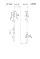
- FIG. 1 is an enlarged, partially fragmentary view, of first and second open die sets with a combined port and seal member shown positioned in spaced apart die elements, partly in section;
- FIG. 2 is a planar fragmentary view of an article in accordance with the present invention.
- FIG. 3 is an enlarged, fragmentary, top planar view of spaced apart first and second die elements in accordance with the present invention
- FIG. 4 is a view taken along line 4--4 of FIG. 3;
- FIG. 5 is a view, partly broken away, illustrating an alternate article in accordance with the present invention.
- FIG. 6 is a schematic view illustrating formation of an alternate seal member in accordance with the invention.
- FIG. 7 is a flow diagram illustrating the steps of a method in accordance with the present invention.
- FIG. 1 illustrates a set 10a of spaced apart die members or elements 12a and 14a.
- the die elements 12a and 14a each include a semi-circular bore, such as the bore 16 formed therein and extending therethrough.
- a semi-circular flange 18 extends axially from each of the die elements. Each flange 18 is oriented toward and is adjacent to a corresponding flange on an adjacent die element.
- the die set 10b includes first and second spaced apart die elements 12b and 14b. Die elements 12b and 14b are shaped corresponding to the elements 12a and 14a, respectively.
- the spaced apart die elements 12a and 14a are designed to receive a cylindrical port 20.
- the port 20 has an interior peripheral surface 22.
- the port 20 might be affixed to a container 24.
- the container 24 could have a closed peripheral boundary 26.
- the present method could be used in combination with containers whose peripheral boundaries have not previously been sealed.
- an important aspect of the present method lies in the fact that it can be used in conjunction with containers, such the container 24, which have a previously sealed periphery.
- a seal member 30 of a generally cylindrical shape includes a sealing membrane 32 which is affixed to an interior peripheral surface 34 of the member 30.
- the member 30 slidably engages the interior peripheral surface 22 of the port 20. When so engaged, the membrane 32 is effective to close the port 20.
- the seal member 30 is affixed to the port 20 in an annular region 40.
- the region 40 is located between the spaced apart die elements 12a and 14a and 12b and 14b.
- the second set of spaced apart die elements 12b and 14b is moved into compression contact with the port 20.
- the two sets of die members 10a and 10b radially compress the port 20 and the seal member 30 in the axial spaces therebetween forming an outwardly extending annular region or ring 42.
- An interior annular depression 44 is formed in the seal member 30 positioned adjacent the annular exterior region 42.
- a radio frequency generator 48 provides radio frequency signals to the spaced apart die elements 12a, 14a and 12b, 14b.
- the signals from the radio frequency generator 48 extend axially along the port 20 and seal member 30 melting and fusing together the material thereof in the region 40.
- This melting and fusing process connects the region 40 to an annular exterior bead or ring 42 of melted material on an exterior peripheral surface 50 of the port 20.
- the annular depression 44 is fixed on the interior surface 34 of the port 30.
- the annular depression 44 is adjacent to but offset from the exterior ring or annular region 42.
- each of the die members 12a, 14a and 12b, 14b includes the axially extending flange 18. These flanges, such as the flange 18 are semicircular in shape.
- the radio frequency electric field is coupled between adjacent flange members.
- FIGS. 3 and 4 are fragmentary, enlarged views of the spaced apart die elements 12a and 14a illustrating the axially extending flanges such as the flange 18.
- the elements 12b and 14b have correspondingly shaped flanges.
- Each of the flanges has a tapered annular peripheral surface 58.
- Surface 58 terminates in a planar, semicircular front surface 60.
- Adequate sealing of the seal member 30 to the port 20 occurs when the annular surface 58 is at an angle 62 on the order of 53 degrees with respect to the die element 12a. Alternately, the angle 62 could be equal to 90 degrees.
- the base or largest radius of the annular surface 58 could be as large as three-quarters of an inch if desired.
- the dimension 60 was on the order of 0.030 inches, and the dimension 64 was on the order of 0.030 inches.
- the dimension 66 was on the order of 0.040 inches.
- the dimension 68 was on the order of 0.030 inches.
- the spacing between the die members, such as 12a and 14a was in a range of 1/16-1/8 inches.
- An exemplary RF generator 48 found to generate an appropriate radio frequency field was a Callanan Model Number 20, 2 kw generator. The following settings gave desired fusing in the region 40 with a PVC port 20 and a PVC seal member 30:
- Variac set at 100%.
- the assembled port 20 and seal member 30 have a diameter in a range of 0.320 inches to 0.325 inches.
- the semicircular bores 16 now form a cylindrical opening through the die elements 20 and 30.
- This cylindrical bore or opening has a diameter in a range of 0.278 inches to 0.281 inches.
- FIG. 5 illustrates an alternate form of an article 74 in accordance with the present invention.
- the article 74 include a tubular hollow body portion 76 which is closed by seal members 78 and 80.
- seal member 78 can be slidably inserted into the body member 76 and a ring seal 82 of the type described above can be formed therebetween.
- the container 76 can then be filled with a selected fluid.
- the second seal member 80 can be slidably inserted therein and a second seal 84 formed therebetween. This results in a sealed container 76 filled with fluid.
- the contents of the container 76 can be accessed by piercing a membrane 86.
- multiple spaced apart ring seals 90 and 92 can be formed in a member 93.
- the multiple seals 90, 92 provide additional security.
- the seals 90, 92 can be formed by a plurality of spaced apart die elements such as 94 through 98. As in the case of FIG. 1, the die elements 94 through 98 would have a corresponding set of laterally displaced die elements which would be brought into contact with the container or port 93 onto which the seals 90, 92 are to be formed.
- These die elements also include flanges such as the flange 18.
- FIG. 7 illustrates in further detail the steps of the method of sealing the port 20 to the seal member 30.
- the seal member 30 is slidably engaged with the port member 20.
- the region wherein the seal member 30 and port member 20 overlap is placed between the first and second elements of die sets 10a and 10b.
- the die sets 10a and 10b are then brought into compression contact with the overlapping region of the seal member 30 and the port 20 therebetween.
- the radio frequency generator 48 is then energized and an axial electric field is created between the die members 12a, 14a and between the die members 12b and 14b. This field heats and melts part of the overlapping region of the seal member 30 and the port member 20 between the respective die elements.
- the annular bead 42 is formed on the exterior peripheral surface of the port member 20.
- the interior annular depression 44 is fixed on the interior peripheral wall 34 of the seal member 30.
Landscapes
- Engineering & Computer Science (AREA)
- Mechanical Engineering (AREA)
- Health & Medical Sciences (AREA)
- Epidemiology (AREA)
- Nursing (AREA)
- Orthopedic Medicine & Surgery (AREA)
- Biomedical Technology (AREA)
- Heart & Thoracic Surgery (AREA)
- Vascular Medicine (AREA)
- Life Sciences & Earth Sciences (AREA)
- Animal Behavior & Ethology (AREA)
- General Health & Medical Sciences (AREA)
- Public Health (AREA)
- Veterinary Medicine (AREA)
- Lining Or Joining Of Plastics Or The Like (AREA)
Abstract
Description
Claims (2)
Priority Applications (1)
| Application Number | Priority Date | Filing Date | Title |
|---|---|---|---|
| US07/231,647 US4900389A (en) | 1986-10-10 | 1988-08-09 | Method of sealing an article via radio frequency |
Applications Claiming Priority (2)
| Application Number | Priority Date | Filing Date | Title |
|---|---|---|---|
| US91816986A | 1986-10-10 | 1986-10-10 | |
| US07/231,647 US4900389A (en) | 1986-10-10 | 1988-08-09 | Method of sealing an article via radio frequency |
Related Parent Applications (1)
| Application Number | Title | Priority Date | Filing Date |
|---|---|---|---|
| US91816986A Continuation | 1986-10-10 | 1986-10-10 |
Publications (1)
| Publication Number | Publication Date |
|---|---|
| US4900389A true US4900389A (en) | 1990-02-13 |
Family
ID=26925307
Family Applications (1)
| Application Number | Title | Priority Date | Filing Date |
|---|---|---|---|
| US07/231,647 Expired - Lifetime US4900389A (en) | 1986-10-10 | 1988-08-09 | Method of sealing an article via radio frequency |
Country Status (1)
| Country | Link |
|---|---|
| US (1) | US4900389A (en) |
Cited By (14)
| Publication number | Priority date | Publication date | Assignee | Title |
|---|---|---|---|---|
| US5203943A (en) * | 1990-12-13 | 1993-04-20 | Minnesota Mining And Manufacturing Company | Method of forming internal strictures in a tubular member and a bonding connection with an inserted tube |
| US5466322A (en) * | 1993-02-04 | 1995-11-14 | Baxter International Inc. | Method for making an elongated plastic member assembly |
| US5789725A (en) * | 1996-01-15 | 1998-08-04 | The Whitaker Corporation | Radio frequency heat sealing of cable assemblies |
| US5840151A (en) * | 1993-02-04 | 1998-11-24 | Baxter International Inc. | Apparatus and dies for forming peelable tube assemblies |
| EP0875362A3 (en) * | 1997-05-02 | 1998-12-23 | Hüls Aktiengesellschaft | Joint between tube and connecting element made by HF welding |
| US6247590B1 (en) | 1999-06-25 | 2001-06-19 | Jamestown Plastics, Inc. | Thermoformed selectively accessed multi-chambered packaging |
| US6305195B1 (en) * | 1999-05-27 | 2001-10-23 | Agere Systems Guardian Corp. | Process for fabricating silica article involving joining of discrete bodies |
| US6367634B1 (en) | 1993-12-22 | 2002-04-09 | Baxter International Inc. | Blood collection systems including an integral, flexible filter |
| US6422397B1 (en) | 1993-12-22 | 2002-07-23 | Baxter International, Inc. | Blood collection systems including an integral, flexible filter |
| US6601710B2 (en) | 1999-04-20 | 2003-08-05 | Baxter International Inc. | Filter assembly having a flexible housing |
| US20030209479A1 (en) * | 2000-07-10 | 2003-11-13 | Lynn Daniel R | Blood filters, blood collection and processing systems, and methods therefore |
| US20060137724A1 (en) * | 2004-12-27 | 2006-06-29 | Powers John M | Method for removing engine deposits from turbie components and composition for use in same |
| US20140138024A1 (en) * | 2006-06-08 | 2014-05-22 | Kiefel Gmbh | Tool for rf welding, arrangement of a central electrode and use of a central electrode |
| DE102016010766A1 (en) | 2016-02-10 | 2017-08-10 | Kiefel Gmbh | TOOL FOR HF WELDING, APPARATUS FOR PRODUCING A BAG FOR MEDICAL PURPOSES AND METHOD FOR OPERATING SUCH A PLANT |
Citations (12)
| Publication number | Priority date | Publication date | Assignee | Title |
|---|---|---|---|---|
| US2816596A (en) * | 1955-08-09 | 1957-12-17 | Fenwal Lab Inc | Dielectric heat sealing method and apparatus |
| US3222590A (en) * | 1962-02-13 | 1965-12-07 | Ritz Hans | High-voltage instrument transformer |
| US3558397A (en) * | 1968-02-15 | 1971-01-26 | Plastronics Inc | Method of making a tube-to-bag connection |
| US3706620A (en) * | 1970-03-13 | 1972-12-19 | Ethylox Products Inc | Method and apparatus for forming the end of a plastic tube and sealing the tube within a flexible container |
| US4417753A (en) * | 1981-05-21 | 1983-11-29 | Baxter Travenol Laboratories, Inc. | Method and apparatus for joining materials |
| US4419095A (en) * | 1980-05-14 | 1983-12-06 | Shiley, Inc. | Cannula with radiopaque tip |
| JPS5942920A (en) * | 1982-09-03 | 1984-03-09 | Kyoraku Co Ltd | Welding method of plastic members |
| JPS5942921A (en) * | 1982-09-03 | 1984-03-09 | Kyoraku Co Ltd | Bonding method of tubular members made of synthetic resin |
| JPS59178214A (en) * | 1983-03-30 | 1984-10-09 | Kyoraku Co Ltd | Welding method of plastic member |
| JPS604030A (en) * | 1983-06-22 | 1985-01-10 | Sumitomo Bakelite Co Ltd | High frequency welding process |
| US4547641A (en) * | 1980-05-14 | 1985-10-15 | Nebergall Perry A | Method for dielectrically joining tubular members |
| US4576671A (en) * | 1983-07-06 | 1986-03-18 | Nippon Medical Supply | Method of manufacturing alate medical needle |
-
1988
- 1988-08-09 US US07/231,647 patent/US4900389A/en not_active Expired - Lifetime
Patent Citations (12)
| Publication number | Priority date | Publication date | Assignee | Title |
|---|---|---|---|---|
| US2816596A (en) * | 1955-08-09 | 1957-12-17 | Fenwal Lab Inc | Dielectric heat sealing method and apparatus |
| US3222590A (en) * | 1962-02-13 | 1965-12-07 | Ritz Hans | High-voltage instrument transformer |
| US3558397A (en) * | 1968-02-15 | 1971-01-26 | Plastronics Inc | Method of making a tube-to-bag connection |
| US3706620A (en) * | 1970-03-13 | 1972-12-19 | Ethylox Products Inc | Method and apparatus for forming the end of a plastic tube and sealing the tube within a flexible container |
| US4419095A (en) * | 1980-05-14 | 1983-12-06 | Shiley, Inc. | Cannula with radiopaque tip |
| US4547641A (en) * | 1980-05-14 | 1985-10-15 | Nebergall Perry A | Method for dielectrically joining tubular members |
| US4417753A (en) * | 1981-05-21 | 1983-11-29 | Baxter Travenol Laboratories, Inc. | Method and apparatus for joining materials |
| JPS5942920A (en) * | 1982-09-03 | 1984-03-09 | Kyoraku Co Ltd | Welding method of plastic members |
| JPS5942921A (en) * | 1982-09-03 | 1984-03-09 | Kyoraku Co Ltd | Bonding method of tubular members made of synthetic resin |
| JPS59178214A (en) * | 1983-03-30 | 1984-10-09 | Kyoraku Co Ltd | Welding method of plastic member |
| JPS604030A (en) * | 1983-06-22 | 1985-01-10 | Sumitomo Bakelite Co Ltd | High frequency welding process |
| US4576671A (en) * | 1983-07-06 | 1986-03-18 | Nippon Medical Supply | Method of manufacturing alate medical needle |
Cited By (26)
| Publication number | Priority date | Publication date | Assignee | Title |
|---|---|---|---|---|
| US5203943A (en) * | 1990-12-13 | 1993-04-20 | Minnesota Mining And Manufacturing Company | Method of forming internal strictures in a tubular member and a bonding connection with an inserted tube |
| US5840151A (en) * | 1993-02-04 | 1998-11-24 | Baxter International Inc. | Apparatus and dies for forming peelable tube assemblies |
| US5466322A (en) * | 1993-02-04 | 1995-11-14 | Baxter International Inc. | Method for making an elongated plastic member assembly |
| US7353956B2 (en) | 1993-12-22 | 2008-04-08 | Fenwal, Inc. | Blood collection systems including a flexible filter |
| US20040149646A1 (en) * | 1993-12-22 | 2004-08-05 | Baxter International Inc. | Blood collection systems including a flexible filter |
| US7278541B2 (en) | 1993-12-22 | 2007-10-09 | Fenwal, Inc. | Method of making a filter assembly having a flexible housing |
| US20040154974A1 (en) * | 1993-12-22 | 2004-08-12 | Baxter International Inc. | Method of making a filter assembly having a flexible housing |
| US6745902B2 (en) | 1993-12-22 | 2004-06-08 | Baxter International Inc. | Blood collection systems including an integral, flexible filter |
| US6367634B1 (en) | 1993-12-22 | 2002-04-09 | Baxter International Inc. | Blood collection systems including an integral, flexible filter |
| US6422397B1 (en) | 1993-12-22 | 2002-07-23 | Baxter International, Inc. | Blood collection systems including an integral, flexible filter |
| US6688476B2 (en) | 1993-12-22 | 2004-02-10 | Baxter International Inc. | Filter assembly having a flexible housing and method of making same |
| US5792988A (en) * | 1996-01-15 | 1998-08-11 | The Whitaker Corporation | Radio frequency heat sealing of cable assemblies |
| US5789725A (en) * | 1996-01-15 | 1998-08-04 | The Whitaker Corporation | Radio frequency heat sealing of cable assemblies |
| EP0875362A3 (en) * | 1997-05-02 | 1998-12-23 | Hüls Aktiengesellschaft | Joint between tube and connecting element made by HF welding |
| US6601710B2 (en) | 1999-04-20 | 2003-08-05 | Baxter International Inc. | Filter assembly having a flexible housing |
| US6305195B1 (en) * | 1999-05-27 | 2001-10-23 | Agere Systems Guardian Corp. | Process for fabricating silica article involving joining of discrete bodies |
| US6247590B1 (en) | 1999-06-25 | 2001-06-19 | Jamestown Plastics, Inc. | Thermoformed selectively accessed multi-chambered packaging |
| US20030209479A1 (en) * | 2000-07-10 | 2003-11-13 | Lynn Daniel R | Blood filters, blood collection and processing systems, and methods therefore |
| US20060137724A1 (en) * | 2004-12-27 | 2006-06-29 | Powers John M | Method for removing engine deposits from turbie components and composition for use in same |
| US20140138024A1 (en) * | 2006-06-08 | 2014-05-22 | Kiefel Gmbh | Tool for rf welding, arrangement of a central electrode and use of a central electrode |
| EP3047960A1 (en) * | 2006-06-08 | 2016-07-27 | Kiefel GmbH | Tool for high frequency welding |
| US9505168B2 (en) * | 2006-06-08 | 2016-11-29 | Kiefel Gmbh | Tool for RF welding, arrangement of a central electrode and use of a central electrode |
| DE102016010766A1 (en) | 2016-02-10 | 2017-08-10 | Kiefel Gmbh | TOOL FOR HF WELDING, APPARATUS FOR PRODUCING A BAG FOR MEDICAL PURPOSES AND METHOD FOR OPERATING SUCH A PLANT |
| WO2017137019A1 (en) | 2016-02-10 | 2017-08-17 | Kiefel Gmbh | Tool for hf welding, installation for producing a bag for medical purposes and method for operating such an installation |
| CN109070482A (en) * | 2016-02-10 | 2018-12-21 | 凯孚尔有限公司 | For the tool of HF welding, it is used to prepare the device of medical bag and the method for operating the device |
| CN109070482B (en) * | 2016-02-10 | 2021-02-23 | 凯孚尔有限公司 | Tool for HF welding, device for producing a medicinal bag and method for operating the device |
Similar Documents
| Publication | Publication Date | Title |
|---|---|---|
| US4900389A (en) | Method of sealing an article via radio frequency | |
| US4836691A (en) | Medical bag and method for preparing the same | |
| US5507904A (en) | Method of making a medical container port tangential to the container | |
| US5823383A (en) | Plastic weld pourer component | |
| US3700513A (en) | Method of making tube | |
| US3728184A (en) | Method of making syringe and needle adapter assembly by ultrasonic bonding | |
| WO1996025341A1 (en) | A collapsible tube package and method of construction | |
| US20180194506A1 (en) | Paper-based composite container for off-gassing products, and method for making same | |
| JPH06510935A (en) | Sterile/aseptic connectors | |
| US4210479A (en) | Method for bonding a plastic tubing to a metal needle and the needle assembly formed thereby | |
| GB1572399A (en) | Plastic container | |
| EP0291515B1 (en) | Radio frequency method of sealing an article | |
| US2914181A (en) | Plastic tube connections | |
| US8424275B2 (en) | Sealed plastic closure and method for making the same | |
| GB8515997D0 (en) | Thermoplastic container | |
| US4521366A (en) | Method for closing and sealing plastic tubing using a hot die and a rotating cold die | |
| JP2821657B2 (en) | Manufacturing method of plastic container | |
| US5453149A (en) | Improved process for effecting electromagnetic bonding of plastic parts | |
| US6179131B1 (en) | Fusion-welded thermoplastic filter assembly and a method of fabricating the same | |
| US4106963A (en) | Method of making an all plastic caulking cartridge | |
| GB2096569A (en) | Plastic bag | |
| JPH0356356B2 (en) | ||
| US6164486A (en) | Integral telescoping vessel joint and method for using the same | |
| JPH10119980A (en) | Production of inner bag for container can | |
| MXPA97006166A (en) | An aplastable tubular package and construction method |
Legal Events
| Date | Code | Title | Description |
|---|---|---|---|
| FEPP | Fee payment procedure |
Free format text: PAYOR NUMBER ASSIGNED (ORIGINAL EVENT CODE: ASPN); ENTITY STATUS OF PATENT OWNER: LARGE ENTITY |
|
| STCF | Information on status: patent grant |
Free format text: PATENTED CASE |
|
| FEPP | Fee payment procedure |
Free format text: PAYER NUMBER DE-ASSIGNED (ORIGINAL EVENT CODE: RMPN); ENTITY STATUS OF PATENT OWNER: LARGE ENTITY Free format text: PAYOR NUMBER ASSIGNED (ORIGINAL EVENT CODE: ASPN); ENTITY STATUS OF PATENT OWNER: LARGE ENTITY |
|
| FPAY | Fee payment |
Year of fee payment: 4 |
|
| FEPP | Fee payment procedure |
Free format text: PAYER NUMBER DE-ASSIGNED (ORIGINAL EVENT CODE: RMPN); ENTITY STATUS OF PATENT OWNER: LARGE ENTITY Free format text: PAYOR NUMBER ASSIGNED (ORIGINAL EVENT CODE: ASPN); ENTITY STATUS OF PATENT OWNER: LARGE ENTITY |
|
| FPAY | Fee payment |
Year of fee payment: 8 |
|
| FPAY | Fee payment |
Year of fee payment: 12 |