US4900333A - Method of carrying out a gas combustion process with recovery of a part of the heat present in the combustion gases - Google Patents
Method of carrying out a gas combustion process with recovery of a part of the heat present in the combustion gases Download PDFInfo
- Publication number
- US4900333A US4900333A US07/098,524 US9852487A US4900333A US 4900333 A US4900333 A US 4900333A US 9852487 A US9852487 A US 9852487A US 4900333 A US4900333 A US 4900333A
- Authority
- US
- United States
- Prior art keywords
- gas
- flue gas
- air
- reformer
- heat
- Prior art date
- Legal status (The legal status is an assumption and is not a legal conclusion. Google has not performed a legal analysis and makes no representation as to the accuracy of the status listed.)
- Expired - Fee Related
Links
Images
Classifications
-
- F—MECHANICAL ENGINEERING; LIGHTING; HEATING; WEAPONS; BLASTING
- F22—STEAM GENERATION
- F22B—METHODS OF STEAM GENERATION; STEAM BOILERS
- F22B33/00—Steam-generation plants, e.g. comprising steam boilers of different types in mutual association
- F22B33/18—Combinations of steam boilers with other apparatus
-
- C—CHEMISTRY; METALLURGY
- C01—INORGANIC CHEMISTRY
- C01B—NON-METALLIC ELEMENTS; COMPOUNDS THEREOF; METALLOIDS OR COMPOUNDS THEREOF NOT COVERED BY SUBCLASS C01C
- C01B3/00—Hydrogen; Gaseous mixtures containing hydrogen; Separation of hydrogen from mixtures containing it; Purification of hydrogen; Reversible storage of hydrogen
- C01B3/02—Production of hydrogen; Production of gaseous mixtures containing hydrogen
- C01B3/32—Production of hydrogen; Production of gaseous mixtures containing hydrogen by reaction of gaseous or liquid organic compounds with gasifying agents, e.g. water, carbon dioxide or air
- C01B3/34—Production of hydrogen; Production of gaseous mixtures containing hydrogen by reaction of gaseous or liquid organic compounds with gasifying agents, e.g. water, carbon dioxide or air by reaction of hydrocarbons with gasifying agents
-
- Y—GENERAL TAGGING OF NEW TECHNOLOGICAL DEVELOPMENTS; GENERAL TAGGING OF CROSS-SECTIONAL TECHNOLOGIES SPANNING OVER SEVERAL SECTIONS OF THE IPC; TECHNICAL SUBJECTS COVERED BY FORMER USPC CROSS-REFERENCE ART COLLECTIONS [XRACs] AND DIGESTS
- Y02—TECHNOLOGIES OR APPLICATIONS FOR MITIGATION OR ADAPTATION AGAINST CLIMATE CHANGE
- Y02P—CLIMATE CHANGE MITIGATION TECHNOLOGIES IN THE PRODUCTION OR PROCESSING OF GOODS
- Y02P20/00—Technologies relating to chemical industry
- Y02P20/10—Process efficiency
- Y02P20/129—Energy recovery, e.g. by cogeneration, H2recovery or pressure recovery turbines
Definitions
- This invention relates to a method of carrying out a gas combustion process with recovery of a part of the heat present in the combustion gases.
- the thermal energy required is obtained by burning gaseous products or hydrocarbons particularly natural gas, that can be easily converted into gaseous products.
- the combustion products (flue gas) released in such processes still contain a substantial amount of thermal energy in the form of sensible heat.
- thermochemical recuperator heat is transferred from the flue gas to a reacting natural gas-steam mixture which is passed over a steam reforming catalyst at high temperature and is converted into a mixture of hydrogen, carbon monoxide and carbon dioxide.
- This reactor much heat is absorbed which is released again in the combustion of the resulting gas mixture (compare "The Thermochemical Recuperator System, Advanced Heat Recovery” by Donald K. Fleming and Mark J. Khinkis, paper presented by the 12th Energy Technology Conference and Exposition, Washington, D.C., Mar. 25-27, 1985).
- the heat of the flue gases leaving the reformer is then transferred, optionally, after an intermediate stage in which the gas/steam mixture is preheated, to a steam boiler in which the steam is generated for the reforming process.
- recuperator/reformer combination may in principle lead to a substantial increase in thermal efficiency, its practical realization has not been possible because of the incontrollability of the process in its non-stationary phase. This also applies when a part of the flue gas is passed from the furnace to the chimney either directly or via the recuperator, quite apart from the accompanying economic losses.
- any cooling medium such as water
- air is used for the purpose.
- the amount of air to be supplied can be readily determined by means of the temperature of the flue gas leaving the combustion furnace, on the one hand, and the reformed gas temperature, on the other hand. This can be carried out using a known per se method by means of temperature sensors in the flue gas introduced into the reforming reactor and in the reformed gas leaving the reforming reactor, the signals of the sensors being used for controlling the amount of cooling medium.
- supplying 10% air having ambient temperature, based on the total volume of the flue gas will lead to a decrease of temperature of 100° C.
- the amount of air to be admixed depends on the place where it is admixed. Because air is preferably admixed after the recuperator and the gas bypass and the temperature of the gases introduced into the reforming reactor may be up to 1100° C., while it may not be higher than 700° C. during the non-stationary phase, the amount of air supplied to the flue gas is initially about 40%, based on the total gas volume, which amount will gradually decrease to 0% during the starting-up phase.
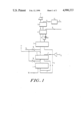
- FIG. 1 is a schematic representation of the method of the invention
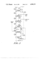
- FIG. 2 is a schematic representation of the temperatures that occur during the "starting-up" phase of the method of the invention.
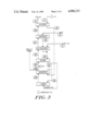
- FIG. 3 is a schematic representation of the temperatures that occur during the "steady-state" phase of the method of the invention.
- the method according to the invention is schematically shown in FIG. 1.
- the combustion gas e.g. having a temperature of 1300° C.
- a gas bypass conduit is indicated which generally branches from the flue gas conduit before the reformer.
- Combustion air is supplied via fan (8) through conduit (7) and an optionally present preheater, which is not shown, said combustion air being preheated in recuperator (2).
- the medium to be burned, especially natural gas, is supplied to the reformer (3) via conduit (9), the preheating section (4) and the desulfurizer (10).
- Water is supplied to steam boiler (5) via conduit (11), the demineralizing unit (12). Steam together with the gas flowing from the desulfurizer (10) is supplied to the reformer (3) via conduit (13). The gases flowing from the reformer are supplied to the combustion furnace via conduit (14). At (15) a conduit is shown which air or another cooling medium, such as water, can be supplied to the recuperator (2) or the reformer (3) by means of valves or taps (16). During the non-stationary phase of the process a hydrocarbon to be burned is supplied via conduit (18).
- this example shows the effect on the process variables of the addition of a cooling medium (air of water) to the flue gases.
- the data are grouped in Table A.
- the temperature of the flue gas just before the recuperator is 1350° C.
- the alternative "O" indicated in the table is the condition in which the entire process, including the reforming reactions, is in the "steady state".
- alternatives 1 through 6 the different possibilities of starting-up the entire process are indicated, i.e. starting from only the use of the recuperator to the realization of the entire process using the complete equipment.
- a relatively small part of the flue gases is passed through the reformer.
- the temperature of the flue gas entering the reformer is decreased from 1030° C. to about 700° C. by admixing air or water.
- Alternatives 1 through 6 indicate the result for a bypass branching before (upstream of) or after (downstream of) the recuperator. As the results show, hardly more heat is transferred by the recuperator when air is admixed before the recuperator. This results in that the (natural) gas consumption is higher and that the chimney system must be much larger so as to enable the processing of the large amount of flue gas.
- Air 1703 natural gas: 189 (direct to furnace, not via reformer)
- Composition of natural gas the same as in Example II.
- Examples I and II show that the amount of air to be admixed can be readily adjusted--especially by determining the highest desired temperature during the different phases of the process--until the stationary condition has been reached and admixture of air to the flue gas is no longer necessary.
Landscapes
- Chemical & Material Sciences (AREA)
- Engineering & Computer Science (AREA)
- Organic Chemistry (AREA)
- Chemical Kinetics & Catalysis (AREA)
- Mechanical Engineering (AREA)
- General Engineering & Computer Science (AREA)
- Physics & Mathematics (AREA)
- Health & Medical Sciences (AREA)
- General Health & Medical Sciences (AREA)
- Combustion & Propulsion (AREA)
- Inorganic Chemistry (AREA)
- Thermal Sciences (AREA)
- Air Supply (AREA)
- Waste-Gas Treatment And Other Accessory Devices For Furnaces (AREA)
- Chimneys And Flues (AREA)
Abstract
Description
                                  TABLE A
__________________________________________________________________________
Different alternatives for cooling flue gas when switching over from TCR
Alternative   0  1     2     3      4      5     6
__________________________________________________________________________
Branch bypass:
              -- after recu-
                       after recu-
                             before recu-
                                    before recu-
                                           after recu-
                                                 before recu-
                 perator
                       perator
                             perator
                                    perator
                                           perator
                                                 perator
Medium admixed in flue gas
              -- air   air   air    air    water water
location admixture
              -- before
                       after before after  after before
                 bypass
                       bypass
                             bypass bypass bypass
                                                 bypass
flue gas temperature before
recuperator (°C.)
              1350
                 1350  1350  724    724    1350  724
flue gas temperature after
recuperator (°C.)
              1083
                 1029  1029  700    700    1029  700
air temperature before
recuperator (°C.)
              350
                 40    40    40     40     40    40
air temperature after
recuperator (°C.)
              800
                 500   500   100    100    500   100
amount of natural gas
Kmol/h        116
                 189   189   286    286    189   286
amount of air to furnace
(Kmol/h)      1035
                 1703  1703  2577   2577   1703  2577
amount of air/water to
flue gas (Kmol/h)
              0  1192  260   3247   260    77    529
amount of flue gas to
reformer (Kmol/h)
              1432
                 690   690   690    690    507   507
amount of flue gas via
bypass (Kmol/h)
              0  2468  1536  5496   2409   1537  2960
total amount of flue gas
(Kmol/h)      1432
                 3158  2227  6186   3099   2041  3464
required power air blower
(Kw)          16 46    46    153    153    46    153
Explanation TCR
              stationary condition
                             starting-up the TCR
__________________________________________________________________________
______________________________________
        Composition of natural gas: (mol %)
______________________________________
        CO.sub.2
             0.89
        CH.sub.4
             81.34
        N.sub.2
             14.32
        C.sub.2
             2.89
        C.sub.3
             0.38
        C.sub.4
             0.18
______________________________________
______________________________________
Gas composition (mol %)
               H.sub.2
                     H.sub.2 O
                            CO  CO.sub.2
                                     CH.sub.4
                                          N.sub.2
                                               O.sub. 2
______________________________________
Reformed gas   --    --     --  --   --
Flue gas       --    18.3   --  11.9 --   68.8 1.0
______________________________________
               power (Mw)
______________________________________
Air preheat      --
Steam boiler     2.87
Gas/steam preheat
                 --
Reformer         --
Recuperator      6.62
Furnace          15.65
______________________________________
______________________________________
Gas composition:
(mol %)      H.sub.2
                    H.sub.2 O
                           CO   CO.sub.2
                                     CH.sub.4
                                          N.sub.2
                                               O.sub.2
______________________________________
Reformed gas 56.7   18.8   10.9 6.5  3.8  3.4  0.6
Flue gas     --     30.2   --   11.7 --   57.4 0.7
______________________________________
               Power (Mw)
______________________________________
Air preheat       2.79
Steam boiler     2.87
Gas/steam preheat
                 1.00
Reformer         6.10
Recuperator      4.17
Furnace          15.65
______________________________________
Claims (4)
Applications Claiming Priority (2)
| Application Number | Priority Date | Filing Date | Title |
|---|---|---|---|
| NL8602404 | 1986-09-23 | ||
| NL8602404A NL8602404A (en) | 1986-09-23 | 1986-09-23 | PROCESS FOR PERFORMING A GAS COMBUSTION PROCESS, RECOVERING A PART OF HEAT PRESENT IN COMBUSTION GASES. |
Publications (1)
| Publication Number | Publication Date |
|---|---|
| US4900333A true US4900333A (en) | 1990-02-13 |
Family
ID=19848581
Family Applications (1)
| Application Number | Title | Priority Date | Filing Date |
|---|---|---|---|
| US07/098,524 Expired - Fee Related US4900333A (en) | 1986-09-23 | 1987-09-18 | Method of carrying out a gas combustion process with recovery of a part of the heat present in the combustion gases |
Country Status (4)
| Country | Link |
|---|---|
| US (1) | US4900333A (en) |
| EP (1) | EP0262727B1 (en) |
| DE (1) | DE3764340D1 (en) |
| NL (1) | NL8602404A (en) |
Cited By (21)
| Publication number | Priority date | Publication date | Assignee | Title |
|---|---|---|---|---|
| US5595059A (en) * | 1995-03-02 | 1997-01-21 | Westingthouse Electric Corporation | Combined cycle power plant with thermochemical recuperation and flue gas recirculation |
| US6113874A (en) * | 1998-04-29 | 2000-09-05 | Praxair Technology, Inc. | Thermochemical regenerative heat recovery process |
| US6210157B1 (en) | 2000-04-07 | 2001-04-03 | Praxair Technology, Inc. | Fuel reformer combustion process |
| US6223519B1 (en) | 1999-02-11 | 2001-05-01 | Bp Amoco Corporation | Method of generating power using an advanced thermal recuperation cycle |
| US6397790B1 (en) | 2000-04-03 | 2002-06-04 | R. Kirk Collier, Jr. | Octane enhanced natural gas for internal combustion engine |
| US6405720B1 (en) | 2000-04-03 | 2002-06-18 | R. Kirk Collier, Jr. | Natural gas powered engine |
| US6508209B1 (en) | 2000-04-03 | 2003-01-21 | R. Kirk Collier, Jr. | Reformed natural gas for powering an internal combustion engine |
| US6739125B1 (en) | 2002-11-13 | 2004-05-25 | Collier Technologies, Inc. | Internal combustion engine with SCR and integrated ammonia production |
| US6767530B2 (en) | 2001-12-14 | 2004-07-27 | Praxair Technology, Inc. | Method for producing hydrogen |
| US20050279333A1 (en) * | 2004-06-22 | 2005-12-22 | Chol-Bum Kweon | Advanced high efficiency, ultra-low emission, thermochemically recuperated reciprocating internal combustion engine |
| US20100237080A1 (en) * | 2009-03-19 | 2010-09-23 | Kautex Textron Gmbh & Co. Kg | Plastic fuel tank |
| US20120264986A1 (en) * | 2011-04-14 | 2012-10-18 | American Iron And Steel Institute | Non-catalytic recuperative reformer |
| JP2015209348A (en) * | 2014-04-25 | 2015-11-24 | 株式会社コスモテックス | Hydrogen production method, hydrogen production apparatus, and reforming reactor for the apparatus |
| US9353623B2 (en) | 2011-03-29 | 2016-05-31 | Liquidpiston, Inc. | Seal assembly for a heat engine |
| US9382851B2 (en) | 2008-08-04 | 2016-07-05 | Liquidpiston, Inc. | Isochoric heat addition engines and methods |
| US9523310B2 (en) | 2004-01-12 | 2016-12-20 | Liquidpiston, Inc. | Hybrid cycle combustion engine and methods |
| US9528435B2 (en) | 2013-01-25 | 2016-12-27 | Liquidpiston, Inc. | Air-cooled rotary engine |
| US9644570B2 (en) | 2006-08-02 | 2017-05-09 | Liquidpiston, Inc. | Hybrid cycle rotary engine |
| US9803153B2 (en) | 2011-04-14 | 2017-10-31 | Gas Technology Institute | Radiant non-catalytic recuperative reformer |
| EP3336430A1 (en) * | 2016-12-15 | 2018-06-20 | Linde Aktiengesellschaft | Method for recuperating heat from a flue gas generated by a burner |
| US11912608B2 (en) | 2019-10-01 | 2024-02-27 | Owens-Brockway Glass Container Inc. | Glass manufacturing |
Families Citing this family (1)
| Publication number | Priority date | Publication date | Assignee | Title |
|---|---|---|---|---|
| EP1650518B1 (en) * | 2003-07-15 | 2012-08-22 | NGK Insulators, Ltd. | Firing furnace and method for firing |
Citations (3)
| Publication number | Priority date | Publication date | Assignee | Title |
|---|---|---|---|---|
| US3446747A (en) * | 1964-08-11 | 1969-05-27 | Chemical Construction Corp | Process and apparatus for reforming hydrocarbons |
| US3738103A (en) * | 1969-09-01 | 1973-06-12 | Metallgesellschaft Ag | Power plant process |
| US4681701A (en) * | 1985-08-30 | 1987-07-21 | Shell Oil Company | Process for producing synthesis gas |
Family Cites Families (1)
| Publication number | Priority date | Publication date | Assignee | Title |
|---|---|---|---|---|
| EP0215930B1 (en) * | 1985-03-25 | 1990-06-27 | SCHICK, Josef Hubert | Process for the production of heat energy from synthetic gas |
-
1986
- 1986-09-23 NL NL8602404A patent/NL8602404A/en not_active Application Discontinuation
-
1987
- 1987-09-18 US US07/098,524 patent/US4900333A/en not_active Expired - Fee Related
- 1987-09-22 DE DE8787201811T patent/DE3764340D1/en not_active Expired - Lifetime
- 1987-09-22 EP EP87201811A patent/EP0262727B1/en not_active Expired - Lifetime
Patent Citations (3)
| Publication number | Priority date | Publication date | Assignee | Title |
|---|---|---|---|---|
| US3446747A (en) * | 1964-08-11 | 1969-05-27 | Chemical Construction Corp | Process and apparatus for reforming hydrocarbons |
| US3738103A (en) * | 1969-09-01 | 1973-06-12 | Metallgesellschaft Ag | Power plant process |
| US4681701A (en) * | 1985-08-30 | 1987-07-21 | Shell Oil Company | Process for producing synthesis gas |
Non-Patent Citations (4)
| Title |
|---|
| Reliability, Efficiency, and Economics of Recuperators in Industrial Applications J. Seehausen; Presented to the 1981 Gas Research Conference in Los Angeles. * |
| Reliability, Efficiency, and Economics of Recuperators in Industrial Applications--J. Seehausen; Presented to the 1981 Gas Research Conference in Los Angeles. |
| The Thermochemical Recuperator System Advanced Heat Recovery, by Donald K. Fleming and Mark J. Khinkis, Institute of Gas Technology; Presented at the 12th Energy Technology Conference and Exposition, Washington, D.C., Mar. 25 27, 1985. * |
| The Thermochemical Recuperator System--Advanced Heat Recovery, by Donald K. Fleming and Mark J. Khinkis, Institute of Gas Technology; Presented at the 12th Energy Technology Conference and Exposition, Washington, D.C., Mar. 25-27, 1985. |
Cited By (26)
| Publication number | Priority date | Publication date | Assignee | Title |
|---|---|---|---|---|
| US5595059A (en) * | 1995-03-02 | 1997-01-21 | Westingthouse Electric Corporation | Combined cycle power plant with thermochemical recuperation and flue gas recirculation |
| US6113874A (en) * | 1998-04-29 | 2000-09-05 | Praxair Technology, Inc. | Thermochemical regenerative heat recovery process |
| US6223519B1 (en) | 1999-02-11 | 2001-05-01 | Bp Amoco Corporation | Method of generating power using an advanced thermal recuperation cycle |
| US6508209B1 (en) | 2000-04-03 | 2003-01-21 | R. Kirk Collier, Jr. | Reformed natural gas for powering an internal combustion engine |
| US6397790B1 (en) | 2000-04-03 | 2002-06-04 | R. Kirk Collier, Jr. | Octane enhanced natural gas for internal combustion engine |
| US6405720B1 (en) | 2000-04-03 | 2002-06-18 | R. Kirk Collier, Jr. | Natural gas powered engine |
| US6210157B1 (en) | 2000-04-07 | 2001-04-03 | Praxair Technology, Inc. | Fuel reformer combustion process |
| US6767530B2 (en) | 2001-12-14 | 2004-07-27 | Praxair Technology, Inc. | Method for producing hydrogen |
| US6739125B1 (en) | 2002-11-13 | 2004-05-25 | Collier Technologies, Inc. | Internal combustion engine with SCR and integrated ammonia production |
| US9523310B2 (en) | 2004-01-12 | 2016-12-20 | Liquidpiston, Inc. | Hybrid cycle combustion engine and methods |
| US20050279333A1 (en) * | 2004-06-22 | 2005-12-22 | Chol-Bum Kweon | Advanced high efficiency, ultra-low emission, thermochemically recuperated reciprocating internal combustion engine |
| US7210467B2 (en) | 2004-06-22 | 2007-05-01 | Gas Technology Institute | Advanced high efficiency, ultra-low emission, thermochemically recuperated reciprocating internal combustion engine |
| US20070137191A1 (en) * | 2004-06-22 | 2007-06-21 | Gas Technology Institute | Advanced high efficiency, ultra-low emission, thermochemically recuperated reciprocating internal combustion engine |
| US9644570B2 (en) | 2006-08-02 | 2017-05-09 | Liquidpiston, Inc. | Hybrid cycle rotary engine |
| US9382851B2 (en) | 2008-08-04 | 2016-07-05 | Liquidpiston, Inc. | Isochoric heat addition engines and methods |
| US9221332B2 (en) * | 2009-03-19 | 2015-12-29 | Kautex Textron Gmbh & Co. Kg | Plastic fuel tank |
| US20100237080A1 (en) * | 2009-03-19 | 2010-09-23 | Kautex Textron Gmbh & Co. Kg | Plastic fuel tank |
| US9353623B2 (en) | 2011-03-29 | 2016-05-31 | Liquidpiston, Inc. | Seal assembly for a heat engine |
| US9216396B2 (en) * | 2011-04-14 | 2015-12-22 | Gas Technology Institute | Non-catalytic recuperative reformer |
| US20120264986A1 (en) * | 2011-04-14 | 2012-10-18 | American Iron And Steel Institute | Non-catalytic recuperative reformer |
| US9803153B2 (en) | 2011-04-14 | 2017-10-31 | Gas Technology Institute | Radiant non-catalytic recuperative reformer |
| US9528435B2 (en) | 2013-01-25 | 2016-12-27 | Liquidpiston, Inc. | Air-cooled rotary engine |
| JP2015209348A (en) * | 2014-04-25 | 2015-11-24 | 株式会社コスモテックス | Hydrogen production method, hydrogen production apparatus, and reforming reactor for the apparatus |
| EP3336430A1 (en) * | 2016-12-15 | 2018-06-20 | Linde Aktiengesellschaft | Method for recuperating heat from a flue gas generated by a burner |
| WO2018108323A1 (en) * | 2016-12-15 | 2018-06-21 | Linde Aktiengesellschaft | Method for recovering heat from a flue gas generated by a burner |
| US11912608B2 (en) | 2019-10-01 | 2024-02-27 | Owens-Brockway Glass Container Inc. | Glass manufacturing |
Also Published As
| Publication number | Publication date |
|---|---|
| EP0262727A1 (en) | 1988-04-06 |
| EP0262727B1 (en) | 1990-08-16 |
| NL8602404A (en) | 1988-04-18 |
| DE3764340D1 (en) | 1990-09-20 |
Similar Documents
| Publication | Publication Date | Title |
|---|---|---|
| US4900333A (en) | Method of carrying out a gas combustion process with recovery of a part of the heat present in the combustion gases | |
| US4315893A (en) | Reformer employing finned heat pipes | |
| CA1065347A (en) | Methanol | |
| US7703271B2 (en) | Cogeneration method and device using a gas turbine comprising a post-combustion chamber | |
| EP0227807B1 (en) | Production of synthesis gas using convective reforming | |
| RU2495914C2 (en) | Apparatus and methods of processing hydrogen and carbon monoxide | |
| CA2470694A1 (en) | Production enhancement for a reactor | |
| JP4059546B2 (en) | Method for producing a combination of synthesis gas and electrical energy | |
| US7718159B2 (en) | Process for co-production of electricity and hydrogen-rich gas steam reforming of a hydrocarbon fraction with input of calories by combustion with hydrogen in situ | |
| GB2213496A (en) | Production of hydrogen-containing gas streams | |
| JPH0132283B2 (en) | ||
| CN101309857B (en) | Method for producing synthesis gas using oxygen-containing gas produced by at least one gas turbine | |
| JP2020508951A (en) | Enhanced waste heat recovery using pre-reformers in combination with oxygen and fuel preheating for combustion | |
| AU682172B2 (en) | New power process | |
| CA1179505A (en) | Method and apparatus for the gaseous reduction of iron ore to sponge iron | |
| US3810975A (en) | Start-up procedure for catalytic steam reforming of hydrocarbons | |
| US5139765A (en) | Dual combustion zone sulfur recovery process | |
| KR100824082B1 (en) | Method of obtaining heating fluid as an indirect heat source for carrying out endothermic reactions | |
| GB2170898A (en) | Method and apparatus for recovering and making available process heat | |
| JP3137143B2 (en) | Temperature control method for fuel cell power plant and fuel cell power plant equipped with temperature control device | |
| US20240391768A1 (en) | Parallel process heating against serial combustion | |
| JPS6130542A (en) | Heat recovery in methanol synthesis reaction | |
| EP0440131B1 (en) | Dual combustion zone sulfor recovery process | |
| WO2023230359A1 (en) | Parallel process heating against serial combustion | |
| PL82215B1 (en) |
Legal Events
| Date | Code | Title | Description |
|---|---|---|---|
| AS | Assignment |
Owner name: VEG-GASINSTITUUT N.V., WILMERSDORF 50, 7327 AC APE Free format text: ASSIGNMENT OF ASSIGNORS INTEREST.;ASSIGNOR:BOS, HUGO T. P.;REEL/FRAME:004803/0240 Effective date: 19870903 Owner name: VEG-GASINSTITUUT N.V., WILMERSDORF 50, 7327 AC APE Free format text: ASSIGNMENT OF ASSIGNORS INTEREST;ASSIGNOR:BOS, HUGO T. P.;REEL/FRAME:004803/0240 Effective date: 19870903 |
|
| CC | Certificate of correction | ||
| FEPP | Fee payment procedure |
Free format text: PAYOR NUMBER ASSIGNED (ORIGINAL EVENT CODE: ASPN); ENTITY STATUS OF PATENT OWNER: LARGE ENTITY |
|
| FPAY | Fee payment |
Year of fee payment: 4 |
|
| REMI | Maintenance fee reminder mailed | ||
| LAPS | Lapse for failure to pay maintenance fees | ||
| FP | Lapsed due to failure to pay maintenance fee |
Effective date: 19980218 |
|
| STCH | Information on status: patent discontinuation |
Free format text: PATENT EXPIRED DUE TO NONPAYMENT OF MAINTENANCE FEES UNDER 37 CFR 1.362 |