US4900290A - Crop delivery system for an axial-flow combine - Google Patents
Crop delivery system for an axial-flow combine Download PDFInfo
- Publication number
- US4900290A US4900290A US07/236,029 US23602988A US4900290A US 4900290 A US4900290 A US 4900290A US 23602988 A US23602988 A US 23602988A US 4900290 A US4900290 A US 4900290A
- Authority
- US
- United States
- Prior art keywords
- crop
- delivery
- rotor
- delivery system
- impeller
- Prior art date
- Legal status (The legal status is an assumption and is not a legal conclusion. Google has not performed a legal analysis and makes no representation as to the accuracy of the status listed.)
- Expired - Lifetime
Links
- 230000007704 transition Effects 0.000 claims abstract description 22
- 238000003306 harvesting Methods 0.000 claims abstract description 18
- 230000004044 response Effects 0.000 claims description 3
- 230000002401 inhibitory effect Effects 0.000 claims description 2
- 230000007246 mechanism Effects 0.000 description 18
- 230000009471 action Effects 0.000 description 6
- 238000004140 cleaning Methods 0.000 description 3
- 230000004048 modification Effects 0.000 description 2
- 238000012986 modification Methods 0.000 description 2
- 230000002093 peripheral effect Effects 0.000 description 2
- 241000687303 Polites vibex Species 0.000 description 1
- 238000009825 accumulation Methods 0.000 description 1
- 238000010276 construction Methods 0.000 description 1
- 230000009977 dual effect Effects 0.000 description 1
- 230000002708 enhancing effect Effects 0.000 description 1
- 238000000034 method Methods 0.000 description 1
- 230000008569 process Effects 0.000 description 1
- 230000001737 promoting effect Effects 0.000 description 1
- 230000009467 reduction Effects 0.000 description 1
Images
Classifications
-
- A—HUMAN NECESSITIES
- A01—AGRICULTURE; FORESTRY; ANIMAL HUSBANDRY; HUNTING; TRAPPING; FISHING
- A01F—PROCESSING OF HARVESTED PRODUCE; HAY OR STRAW PRESSES; DEVICES FOR STORING AGRICULTURAL OR HORTICULTURAL PRODUCE
- A01F12/00—Parts or details of threshing apparatus
- A01F12/10—Feeders
Definitions
- the present invention relates generally to harvesting machines and, more particularly, to an axial-flow combine having an apparatus for improving crop delivery to a threshing apparatus of the combine.
- Rotary combines are available in various designs and models to perform the basic functions of harvesting, threshing, and cleaning of grain or other crop materials.
- a typical combine includes a crop harvesting apparatus which reaps planted grain stalks and then feeds the grain stalks to a separating or threshing apparatus.
- the grain stalks or other crop harvested in the field is rearwardly moved from the crop harvesting apparatus toward the threshing apparatus by a crop feeder mechanism.
- the threshing apparatus includes a power driven rotor mounted inside a stationary cylindrical threshing cage.
- the rotor is supported at opposite ends by bearings.
- the rotor has a series of blades at its forward end defining an impeller.
- the rotor threshes and separates the grain from the material other than grain.
- the grain is threshed several times repeatedly, but gently, as its spirals around the rotor and passes through openings in the threshing cage. Essentially, most material other than grain stays within the threshing cage and is directed out the rear of the combine.
- Transition housing Extending forwardly from the threshing cage and surrounding the impeller is a transition housing.
- Transition housing has an inlet end which opens to the front of the combine and an outlet end which opens to the threshing apparatus.
- the feeder mechanism exhausts crop to the inlet end of the transition housing.
- the internal surface of the transition housing is provided with a series of helically shaped transport vanes for axially conveying or displacing crop material rearwardly between the feeder mechanism and the threshing cage.
- the rotor of the threshing apparatus is rotatably driven at speeds ranging between 400 and 1100 rpm. Rotor speed will be determined as a function of the crop being harvested.
- the impeller blades on the front end of the rotor turn at the same speed as the rotor.
- the impeller blades accept crop from the feeder mechanism and are intended to move the crop peripherally outward toward the helical transport vanes for subsequent delivery to the rotor of the threshing apparatus.
- Residual crop that is not accepted by the blades or is not peripherally moved toward the helical transport vanes tends to whirl about a forward face of the impeller.
- Such residual crop also has a tendency to wrap about the front bearing of the rotor causing operational problems for the combine.
- removal and cleaning of such entangled crop from about the front rotor bearing is a time consuming process which detracts from the combine's efficiency.
- residual crop creates a back-feed problem for the feeder mechanism. As will be understood, such residual crop consumes power and destroys the effectiveness of the combine.
- a device which improves crop delivery from the feeder mechanism to the transport vanes for subsequent delivery to the threshing apparatus in a manner reducing or avoiding back-feed to the feeder mechanism and prevents crop from wrapping about the front rotor bearing.
- an improved crop delivery system for a combine having a threshing apparatus including a rotor with an impeller at a forward end thereof.
- the improved delivery system of the present invention includes a crop delivery vane assembly arranged at the forward end of the impeller for promoting crop movement from the center of the impeller peripherally outward and rearward in a manner substantially avoiding back-feed to the feeder mechanism and which prevents crop entanglement with a forward end of the rotor.
- the crop delivery system of the present invention is used in combination with an axial-flow combine having a crop harvesting apparatus at a forward end of the combine.
- the combine further includes a threshing apparatus including a threshing cage with an elongated rotor journaled at its forward and rear ends by bearings and which is rotatably driven about an axis.
- the rotor has a series of blades defining an impeller at its forward end.
- the improved crop delivery system of the present invention is interposed between the crop harvesting apparatus and the threshing apparatus.
- a crop feeder mechanism rearwardly moves crop from the harvesting apparatus toward the threshing apparatus.
- a transition housing or casing having a series of open ended spiral transport vanes arranged in its inside surface, surrounds the impeller. The transport vanes accept crop from the impeller and direct it rearwardly toward the threshing apparatus in response to impeller rotation.
- a salient feature of the present invention concerns a crop delivery vane assembly.
- the crop delivery vane assembly is arranged within the transition housing substantially normal to the rotational axis of the rotor.
- the vane assembly is arranged in crop receiving relation with the feeder mechanism and acts to positively move crop rearwardly and peripherally outward toward the transport vanes.
- the vane assembly comprises a plurality of spiral shaped delivery vanes which are radially spaced from each other and define channels therebetween.
- Each delivery vane has a gradual involute shape which provides a greater than 90° included angle between a front edge of the impeller blade and the delivery vane. This relationship promotes peripheral crop movement from the rotor center toward the transport vanes and prevents scissoring of the crop material in its peripheral movement toward the transport vanes.
- the vane assembly further includes an anti-wrap vane which protects the forward rotor bearing from crop material which has a tendency to wrap thereabout.
- the anti-wrap vane defines an inner anti-wrap stripper which creates a self cleaning action for the front rotor bearing during rotation of the rotor.
- the delivery vanes of the vane assembly positively direct and promote crop material flow toward a ramp surface provided at the terminal end of each delivery vane.
- Each ramp surface positively moves crop material rearwardly toward an inlet of the transport vanes.
- stripper blade in combination with the crop delivery vane assembly.
- the stripper blade depends from the crop delivery vane assembly and preferably extends across the width of the crop feeder mechanism for directing crop material from the feeder mechanism in a manner inhibiting back-feed on the return run of the conveyor.
- Such a crop delivery vane assembly contemplates a reduction in back-feed to the conveyor and reduces crop entanglement about the front rotor bearing. Moreover, the vane assembly of the present invention reduces power requirements of the combine.
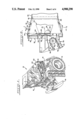
- FIG. 1 is a fragmentary perspective view, partially broken away, of a combine equipped with the present invention
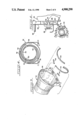
- FIG. 2 is a sectional view taken along line 2--2 of FIG. 1;
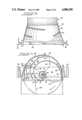
- FIG. 3 is a perspective illustration of a transition housing with transport vanes which are securable within the housing
- FIG. 4 is a front elevational view of a transition housing having the transport vanes secured therewithin;
- FIG. 5 is a top plan view, partially broken away, illustrating a transition housing having transport vanes secured therewithin;
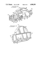
- FIG. 6 is a fragementary side sectional view of a crop delivery vane assembly of the present invention as mounted within the combine;
- FIG. 7 is a rear elevational view of the crop delivery vane assembly of the present invention.
- FIG. 8 is a rear perspective view of the crop delivery vane assembly of the present invention.
- FIG. 9 is a front perspective view of the crop delivery vane assembly of the present invention.
- FIG. 1 a self propelled combine 10 having front drive wheels 12.
- the combine further includes a body 14 having an interconnected supporting structure or frame and which defines an operator's station 16.
- combine 10 At its front end, combine 10 is provided with a crop harvesting apparatus or header 18 which can be of any suitable design.
- the combine is operatively powered by an engine (not shown) suitably housed within body 14, which provides driving power for the combine.
- the transfer of rotation and power from the engine to the various driven components of the combine is of a conventional nature and could include fixed or variable belt or chain drives which are not shown for purposes of clarity.
- the crop harvesting apparatus 18 cuts and directs crop material toward a separating or threshing apparatus 20.
- Threshing apparatus 20 is rotatably supported by and is enclosed within body 14. In FIG. 1, a side wall of body 14 is broken away so that the threshing apparatus 20 of the combine can be seen.
- the threshing apparatus 20 is illustrated as being of an axial-flow type which includes a threshing cage 22. Located within the threshing cage 22 is a coaxially disposed rotor 24. At its forward end, rotor 24 has a series of blades 26 defining an impeller 28.
- the general form of such self propelled combine with axial-flow separator is well known and only a brief description is provided here.
- the crop delivery system of the present invention is interposed between the crop harvesting apparatus 18 and the threshing apparatus 20.
- the crop delivery system of the present invention includes, in combination, a crop feeder mechanism 30, a transition casing or housing 32 including a series of spiral transport vanes 34, and a crop delivery vane assembly 36.
- crop feeder mechanism 30 is pivotally connected to a forward end of the combine.
- the crop feeder mechanism 30 preferably includes a feeder housing 38 having a floor 40 and a conveyor 42 rotatably mounted in the housing 38.
- Conveyor 42 includes a pair of laterally spaced, endless drive chains 44 rotatably mounted in housing 38 on sprockets 46.
- a plurality of laterally elongated drag bars 48 are connected to the chains 44. Drag bars 48 move harvested crop material from the harvesting apparatus 18 across the feeder housing floor 40. Thereafter, drag bars 48 cause the harvested crop material to be fed or directed toward the impeller 28 of rotor 24.
- the direction of conveyor movement is counterclock-wise.
- the forward end of the impeller blades 26 are disposed proximate to a discharge end of the crop feeder mechanism 30.
- the transition casing 32 Surrounding the impeller 28 is the transition casing 32.
- housing 32 extends forwardly from the threshing cage 22. Transition housing 32 defines an inlet end 50 which opens to the front of the combine and to the feeder mechanism 30 and an exit end 52 which opens to the threshing cage 22.
- each transport vane 34 is removably secured to housing 32.
- each transport vane 34 arranged within housing 32 defines an inlet 58 and an outlet 60.
- the inlet 58 of each transport vane is arranged forward of the outlet 60.
- the inlet 58 of one transport vane is radially spaced from an inlet of another transport vane.
- the transport vanes 34 act to direct crop material rearwardly in a "spiraling" manner from the inlet end 50 of the housing 32 toward the outlet end 52 of the housing 32 leading to the threshing apparatus 22.
- Crop delivery vane assembly 36 is arranged within and across the transition housing 32.
- the valve assembly lies in a plane extending substantially normal to the rotational axis of rotor 24 and in crop receiving relation with crop feeder 30.
- Vane assembly 36 serves a dual purpose. First, vane assembly 36 acts as a bearing support for the forward end of rotor 24. Additionally, vane assembly 36 acts to positively and peripherally move crop toward the transport vanes 34 and axially rearward of the combine.
- Vane assembly 36 includes a transversely extended mounting bracket 62. Opposite ends of bracket 62 are provided with mounting plates 64 (FIG. 7). Mounting plates 64 facilitate securement of bracket 62 to the body 14 of the combine. As best illustrated in FIGS. 6, 7, 8 and 9, mounting bracket 62 defines an aperture 66.
- a forward rotor bearing block 68 is suitably secured to the bracket 62 in general alignment with aperture 66.
- Rotor 24 is provided with a forwardly extending axial stub shaft 70.
- Shaft 70 is journalled for rotation in bearing block 68.
- a similar rotatable mounting arrangement is provided at the opposite end of rotor 24.
- rotor 24 is mounted for rotation about an extended axis 72. As illustrated, the majority of the crop delivery vane assembly 36 is arranged above the rotational axis 72 of rotor 24. Moreover, the discharge end of the crop feeder 30 is located beneath the rotational axis 72 of rotor 24.
- the crop delivery vane assembly 36 preferably includes a stripper 74 which depends from mounting bracket 62.
- a free end of stripper 74 is proximately arranged relative to the conveyor 42 to urge crop material rearwardly toward the impeller 28.
- crop delivery vane assembly 36 further includes a plurality of delivery vanes 76 which project rearwardly from and substantially perpendicular to bracket 62.
- Each vane 76 has a gradual involute shape and is radially spaced from an adjacent vane to define a recessed channel 78 therebetween.
- each channel 78 is open at its lower end to receive crop material which is swept into the channel under the influence of impeller 28.
- a lower end of each delivery vane 76 defines an upwardly inclined surface 80 which promotes the passage of crop material therepast.
- the radial innermost delivery vane 76 is arcuately extended to define an anti-wrap vane section 82.
- anti-wrap vane section 82 encompasses and protects rotor shaft 70 from having crop material wound thereabout.
- vane section 82 defines a stripper blade 84 which will act to strip or cut away crop material that becomes entangled about shaft 70 and could impair operation of rotor 24.
- vane assembly 36 further includes an upper door 86 which is removably secured to bracket 62 and defines a vertical extension thereof.
- Door 86 is removably secured at its lower end to mounting bracket 62.
- Door 86 further includes a mounting flange 88 which facilitates securement of door 86 within the confines of transition housing 32.
- door 86 includes a plurality of radially spaced delivery vanes 90 which define recessed channels 92 therebetween. Each delivery vane 90 has a gradual involute shape. When door 86 is suitably positioned on bracket 62, vanes 90 are designed to coact with vanes 76 on bracket 62 and act as extensions thereof.
- each impeller blade 26 is schematically represented in phantom lines.
- the gradual involute shape of each vane of the vane assembly 36 provides a greater than 90° included angle ⁇ between a front edge of each impeller blade and the delivery vane. This relationship promotes crop movement from the center of the rotor toward the periphery of the impeller and to the transport vanes 34.
- a scissoring action of the crop material against the vanes is substantially eliminated to assure proper flow of the crop material through the channels thereby enhancing the ability of vane assembly 36 to positively move crop material toward the transport vanes 34.
- Vane assembly 36 further defines a plurality of ramp surfaces 94 located toward a terminal end of each delivery vane.
- the ramp surfaces 94 extend rearwardly away from bracket 62 and toward the threshing apparatus 20. As best illustrated in FIG. 7, the terminal end of each ramp surface 94 is arranged proximate to an inlet 58 to a transport vane 34.
- the crop harvesting apparatus or header 18 reaps planted crop material and delivers it to the crop feeder 30.
- Conveyor 42 of the crop feeder 30 receives the harvested crop and feeds it toward the threshing apparatus 20.
- stripper 74 acts to urge crop material toward the impeller 28 and inhibit back-feed onto the upper return run of the conveyor.
- Crop material is discharged from the feeder mechanism 30 into the rotating impeller 28.
- the rotary action of the impeller 28 normally causes the crop material discharged toward the periphery of the impeller to move radially outwardly toward any one of several inlets 58 leading to the transport vanes 34.
- the whirling rotary action of impeller 28 forcibly directs other crop material, disposed on the crop feeder 30 closer to the rotary axis of the impeller, into the plurality of recessed channels defined by crop delivery vane assembly 36. That is, the whirling action of the impeller blades 26, in combination with the spiral-like or involuted design of the delivery vanes positively moves crop material peripherally outward toward the transport vanes 34 on the transition housing.
- Ramp surfaces 94 positively move the crop material rearward and, furthermore, introduces crop material to the inlets 58 of the transport vanes and, subsequently, toward the threshing apparatus.
- the crop material introduced into the crop delivery vane assembly 36 is entrapped therein as it positively and peripherally moves along the recessed channels defined by the delivery vanes.
- Such construction reduces the residual crop present at the front of the rotor and, thereby reduces back-feed to the conveyor 42.
- door 86 on the vane assembly 36 may be readily removed so as to provide access to the impeller 28. As such, the condition of the transport vanes 34 or the impeller blades 26 may be regularly checked without having to disassemble the front of the rotor.
- Stripper blade 84 associated therewith effectively prevents an accumulation of crop material about the rotor shaft 70.
- the material acted upon by the stripper blade 84 is discharged into a channel and is directed away from the forward end of the rotor so as to prevent a build-up of material thereabout.
- the delivery vanes of the vane assembly 36 are formed with a greater than 90° included angle between the front edge of an impeller blade and each delivery vane to avoid scissoring action of the material in the channels of the vane assembly. As such, a free flow of material toward the ramp surfaces 94 and, ultimately, to the transport vanes 34 is assured thereby preventing blockage of any one or more of the channels by crop material.
Landscapes
- Life Sciences & Earth Sciences (AREA)
- Environmental Sciences (AREA)
- Threshing Machine Elements (AREA)
Abstract
Description
Claims (5)
Priority Applications (2)
| Application Number | Priority Date | Filing Date | Title |
|---|---|---|---|
| US07/236,029 US4900290A (en) | 1988-08-24 | 1988-08-24 | Crop delivery system for an axial-flow combine |
| CA000594994A CA1280659C (en) | 1988-08-24 | 1989-03-29 | Crop delivery system for an axial-flow combine |
Applications Claiming Priority (1)
| Application Number | Priority Date | Filing Date | Title |
|---|---|---|---|
| US07/236,029 US4900290A (en) | 1988-08-24 | 1988-08-24 | Crop delivery system for an axial-flow combine |
Publications (1)
| Publication Number | Publication Date |
|---|---|
| US4900290A true US4900290A (en) | 1990-02-13 |
Family
ID=22887830
Family Applications (1)
| Application Number | Title | Priority Date | Filing Date |
|---|---|---|---|
| US07/236,029 Expired - Lifetime US4900290A (en) | 1988-08-24 | 1988-08-24 | Crop delivery system for an axial-flow combine |
Country Status (2)
| Country | Link |
|---|---|
| US (1) | US4900290A (en) |
| CA (1) | CA1280659C (en) |
Cited By (22)
| Publication number | Priority date | Publication date | Assignee | Title |
|---|---|---|---|---|
| US5145461A (en) * | 1991-03-21 | 1992-09-08 | Case Corporation | Door assembly for an axial-flow combine |
| US5257959A (en) * | 1991-03-21 | 1993-11-02 | Case Corporation | Door assembly for an axial-flow combine |
| US5346429A (en) * | 1993-02-24 | 1994-09-13 | Case Corporation | Feeder assembly for a combine |
| US5368522A (en) * | 1993-04-14 | 1994-11-29 | Case Corporation | Feeder-rotor assembly for combines |
| US5387153A (en) * | 1993-04-06 | 1995-02-07 | Case Corporation | Rotary combine |
| EP0617884A3 (en) * | 1993-03-31 | 1995-03-01 | Deere & Co | Sheet-metal inlet from an axial separator. |
| US5497605A (en) * | 1994-11-15 | 1996-03-12 | Deere & Company | Header and feeder for a grain combine |
| US5797793A (en) * | 1996-03-07 | 1998-08-25 | Case Corporation | Residue spreading apparatus for agricultural combines |
| EP1214873A1 (en) * | 2000-12-14 | 2002-06-19 | CLAAS Selbstfahrende Erntemaschinen GmbH | Crop delivering system for an axial-flow combine |
| US6688970B2 (en) * | 2001-11-15 | 2004-02-10 | Case Corporation | Combine threshing rotor front bearing and inlet section with anti-wind geometry |
| US20050020328A1 (en) * | 2003-07-21 | 2005-01-27 | Linder Charles D | Spin formed transition section |
| US20060194627A1 (en) * | 2005-02-28 | 2006-08-31 | Cnh America Llc | Combine threshing rotor front bearing and inlet section with anti-wind features |
| US20060223598A1 (en) * | 2005-04-01 | 2006-10-05 | Cnh America Llc | Anti-wind wiper with adjustable extension |
| WO2015075516A1 (en) * | 2013-11-25 | 2015-05-28 | Agco Corporation | Vane arrangement in combine harvester processor |
| US10123485B2 (en) * | 2015-10-16 | 2018-11-13 | Cnh Industrial America Llc | Tapered vane for agricultural harvester transition cone |
| US20190133041A1 (en) * | 2017-11-08 | 2019-05-09 | Cnh Industrial America Llc | Rotor Cage To Transition Cone Interface For Agricultural Harvester |
| US10420285B2 (en) | 2017-06-16 | 2019-09-24 | Cnh Industrial America Llc | Transition device for a combine threshing system |
| US11013181B2 (en) | 2017-11-17 | 2021-05-25 | Cnh Industrial America Llc | Adjustable infeed vanes |
| US11116137B2 (en) | 2018-04-12 | 2021-09-14 | Cnh Industrial America Llc | Concave ramp for an agricultural vehicle |
| US11147213B2 (en) * | 2019-01-03 | 2021-10-19 | Cnh Industrial America Llc | Threshing section of a combine |
| US11266072B2 (en) * | 2019-05-10 | 2022-03-08 | Deere & Company | Separator module for an agricultural machine |
| US20230210055A1 (en) * | 2021-12-30 | 2023-07-06 | Cnh Industrial America Llc | Variable cross-section vane for transition cone in combine harvester |
Citations (9)
| Publication number | Priority date | Publication date | Assignee | Title |
|---|---|---|---|---|
| US3529645A (en) * | 1968-09-24 | 1970-09-22 | Int Harvester Co | Axial-flow sheller and grinder combine |
| US3556108A (en) * | 1968-12-16 | 1971-01-19 | Int Harvester Co | Combine grain cleaner |
| US3827443A (en) * | 1973-06-29 | 1974-08-06 | Int Harvester Co | Conical transition |
| US3828794A (en) * | 1973-06-29 | 1974-08-13 | Int Harvester Co | Crop-diverting shed bar and bearing protector for axial flow-type combines |
| US4248249A (en) * | 1979-07-02 | 1981-02-03 | International Harvester Company | Combine rotor drive anti-trash system |
| US4250896A (en) * | 1979-06-11 | 1981-02-17 | Sperry Corporation | Anti-wrap means |
| US4291709A (en) * | 1980-07-02 | 1981-09-29 | Sperry Corporation | Infeed geometry |
| US4489733A (en) * | 1982-08-18 | 1984-12-25 | Probe Adventures, Inc. | Axial flow combine |
| US4665929A (en) * | 1986-07-21 | 1987-05-19 | Helm William N | Axial flow combine harvester feed plate |
-
1988
- 1988-08-24 US US07/236,029 patent/US4900290A/en not_active Expired - Lifetime
-
1989
- 1989-03-29 CA CA000594994A patent/CA1280659C/en not_active Expired - Lifetime
Patent Citations (9)
| Publication number | Priority date | Publication date | Assignee | Title |
|---|---|---|---|---|
| US3529645A (en) * | 1968-09-24 | 1970-09-22 | Int Harvester Co | Axial-flow sheller and grinder combine |
| US3556108A (en) * | 1968-12-16 | 1971-01-19 | Int Harvester Co | Combine grain cleaner |
| US3827443A (en) * | 1973-06-29 | 1974-08-06 | Int Harvester Co | Conical transition |
| US3828794A (en) * | 1973-06-29 | 1974-08-13 | Int Harvester Co | Crop-diverting shed bar and bearing protector for axial flow-type combines |
| US4250896A (en) * | 1979-06-11 | 1981-02-17 | Sperry Corporation | Anti-wrap means |
| US4248249A (en) * | 1979-07-02 | 1981-02-03 | International Harvester Company | Combine rotor drive anti-trash system |
| US4291709A (en) * | 1980-07-02 | 1981-09-29 | Sperry Corporation | Infeed geometry |
| US4489733A (en) * | 1982-08-18 | 1984-12-25 | Probe Adventures, Inc. | Axial flow combine |
| US4665929A (en) * | 1986-07-21 | 1987-05-19 | Helm William N | Axial flow combine harvester feed plate |
Non-Patent Citations (2)
| Title |
|---|
| Parts Catalog, Case/IH, 1680 Combine, Issued Jul. 1988, drawing Nos. 9 432 and 9 438. * |
| Parts Catalog, Case/IH, 1680 Combine, Issued Jul. 1988, drawing Nos. 9-432 and 9-438. |
Cited By (34)
| Publication number | Priority date | Publication date | Assignee | Title |
|---|---|---|---|---|
| US5145461A (en) * | 1991-03-21 | 1992-09-08 | Case Corporation | Door assembly for an axial-flow combine |
| US5257959A (en) * | 1991-03-21 | 1993-11-02 | Case Corporation | Door assembly for an axial-flow combine |
| US5346429A (en) * | 1993-02-24 | 1994-09-13 | Case Corporation | Feeder assembly for a combine |
| EP0617884A3 (en) * | 1993-03-31 | 1995-03-01 | Deere & Co | Sheet-metal inlet from an axial separator. |
| US5387153A (en) * | 1993-04-06 | 1995-02-07 | Case Corporation | Rotary combine |
| US5368522A (en) * | 1993-04-14 | 1994-11-29 | Case Corporation | Feeder-rotor assembly for combines |
| US5497605A (en) * | 1994-11-15 | 1996-03-12 | Deere & Company | Header and feeder for a grain combine |
| US5797793A (en) * | 1996-03-07 | 1998-08-25 | Case Corporation | Residue spreading apparatus for agricultural combines |
| EP1214873A1 (en) * | 2000-12-14 | 2002-06-19 | CLAAS Selbstfahrende Erntemaschinen GmbH | Crop delivering system for an axial-flow combine |
| US6679773B2 (en) * | 2000-12-14 | 2004-01-20 | Claas Selbstfahrende Erntemaschinen Gmbh | Working devices contained in a rotor housing of an agricultural harvester |
| US6688970B2 (en) * | 2001-11-15 | 2004-02-10 | Case Corporation | Combine threshing rotor front bearing and inlet section with anti-wind geometry |
| US20050020328A1 (en) * | 2003-07-21 | 2005-01-27 | Linder Charles D | Spin formed transition section |
| US20060194627A1 (en) * | 2005-02-28 | 2006-08-31 | Cnh America Llc | Combine threshing rotor front bearing and inlet section with anti-wind features |
| US20060205453A1 (en) * | 2005-02-28 | 2006-09-14 | Tanis Dale R | Combine threshing rotor front bearing and inlet section with anti-wind features |
| US20060205454A1 (en) * | 2005-02-28 | 2006-09-14 | Tanis Dale R | Combine threshing rotor front bearing and inlet section with anti-wind features |
| US7186177B2 (en) | 2005-02-28 | 2007-03-06 | Cnh America Llc | Combine threshing rotor front bearing and inlet section with anti-wind features |
| US7186178B2 (en) | 2005-02-28 | 2007-03-06 | Cnh America Llc | Combine threshing rotor front bearing and inlet section with anti-wind features |
| US7166025B2 (en) | 2005-02-28 | 2007-01-23 | Cnh America Llc | Combine threshing rotor front bearing and inlet section with anti-wind features |
| US20070004478A1 (en) * | 2005-04-01 | 2007-01-04 | Tanis Dale R | Method of adjusting an anti-wind wiper assembly |
| US20060223598A1 (en) * | 2005-04-01 | 2006-10-05 | Cnh America Llc | Anti-wind wiper with adjustable extension |
| US7223167B2 (en) | 2005-04-01 | 2007-05-29 | Cnh America Llc | Anti-wind wiper with adjustable extension |
| WO2015075516A1 (en) * | 2013-11-25 | 2015-05-28 | Agco Corporation | Vane arrangement in combine harvester processor |
| US10051790B2 (en) | 2013-11-25 | 2018-08-21 | Agco Corporation | Vane arrangement in combine harvester processor |
| US11083136B2 (en) * | 2015-10-16 | 2021-08-10 | Cnh Industrial America Llc | Tapered vane for agricultural harvester transition cone |
| US10123485B2 (en) * | 2015-10-16 | 2018-11-13 | Cnh Industrial America Llc | Tapered vane for agricultural harvester transition cone |
| US10420285B2 (en) | 2017-06-16 | 2019-09-24 | Cnh Industrial America Llc | Transition device for a combine threshing system |
| US20190133041A1 (en) * | 2017-11-08 | 2019-05-09 | Cnh Industrial America Llc | Rotor Cage To Transition Cone Interface For Agricultural Harvester |
| US10694677B2 (en) * | 2017-11-08 | 2020-06-30 | Cnh Industrial America Llc | Rotor cage to transition cone interface for agricultural harvester |
| US11013181B2 (en) | 2017-11-17 | 2021-05-25 | Cnh Industrial America Llc | Adjustable infeed vanes |
| US11116137B2 (en) | 2018-04-12 | 2021-09-14 | Cnh Industrial America Llc | Concave ramp for an agricultural vehicle |
| US11147213B2 (en) * | 2019-01-03 | 2021-10-19 | Cnh Industrial America Llc | Threshing section of a combine |
| US11266072B2 (en) * | 2019-05-10 | 2022-03-08 | Deere & Company | Separator module for an agricultural machine |
| US20230210055A1 (en) * | 2021-12-30 | 2023-07-06 | Cnh Industrial America Llc | Variable cross-section vane for transition cone in combine harvester |
| US12369529B2 (en) * | 2021-12-30 | 2025-07-29 | Cnh Industrial America Llc | Variable cross-section vane for transition cone in combine harvester |
Also Published As
| Publication number | Publication date |
|---|---|
| CA1280659C (en) | 1991-02-26 |
Similar Documents
| Publication | Publication Date | Title |
|---|---|---|
| US4900290A (en) | Crop delivery system for an axial-flow combine | |
| US5145462A (en) | Infeed assembly for an axial-flow combine | |
| US4062366A (en) | Rethresher | |
| US5387153A (en) | Rotary combine | |
| US3848609A (en) | Axial flow type harvesting machines | |
| CA1076445A (en) | Swept back impeller blade for axial flow rotor | |
| US4906219A (en) | Cleaning system for a combine | |
| CA1251709A (en) | Feeding arrangement for an axial flow rotary separator | |
| US4248248A (en) | Interrupted infeed flight means for combine rotor | |
| CA1040044A (en) | Concave for an axial flow type combine | |
| US5257959A (en) | Door assembly for an axial-flow combine | |
| US6296566B1 (en) | Infeed impeller for a rotary combine | |
| US3982548A (en) | Helical element rotor-axial flow combine | |
| US5145461A (en) | Door assembly for an axial-flow combine | |
| US5368522A (en) | Feeder-rotor assembly for combines | |
| EP1872647B1 (en) | Chevron inlet for cross flow fan | |
| US6688970B2 (en) | Combine threshing rotor front bearing and inlet section with anti-wind geometry | |
| US4986794A (en) | Rotor assembly for an axial-flow combine | |
| EP1872646B1 (en) | Rotating inlet for cross flow fan. | |
| US20020022505A1 (en) | Circumferential thresher | |
| US6830512B2 (en) | Shroud for the infeed impeller of a rotary combine | |
| US4248249A (en) | Combine rotor drive anti-trash system | |
| US4175568A (en) | Material flow retarders | |
| US6974384B2 (en) | Tailings conveyor with rotary impellers disposed and rotatable at progressively faster speeds for threshing and conveying tailings through the conveyor and method of operation of the same | |
| US6908378B2 (en) | Threshing rotor inlet flight extension |
Legal Events
| Date | Code | Title | Description |
|---|---|---|---|
| AS | Assignment |
Owner name: J. I. CASE COMPANY, (A DE. CORP.) Free format text: ASSIGNMENT OF ASSIGNORS INTEREST.;ASSIGNOR:TANIS, DALE R.;REEL/FRAME:004951/0126 Effective date: 19880816 Owner name: J. I. CASE COMPANY,STATELESS Free format text: ASSIGNMENT OF ASSIGNORS INTEREST;ASSIGNOR:TANIS, DALE R.;REEL/FRAME:004951/0126 Effective date: 19880816 |
|
| STCF | Information on status: patent grant |
Free format text: PATENTED CASE |
|
| FEPP | Fee payment procedure |
Free format text: PAYOR NUMBER ASSIGNED (ORIGINAL EVENT CODE: ASPN); ENTITY STATUS OF PATENT OWNER: LARGE ENTITY |
|
| FEPP | Fee payment procedure |
Free format text: PAYER NUMBER DE-ASSIGNED (ORIGINAL EVENT CODE: RMPN); ENTITY STATUS OF PATENT OWNER: LARGE ENTITY Free format text: PAYOR NUMBER ASSIGNED (ORIGINAL EVENT CODE: ASPN); ENTITY STATUS OF PATENT OWNER: LARGE ENTITY |
|
| AS | Assignment |
Owner name: CASE CORPORATION, A CORP. OF DELAWARE Free format text: CHANGE OF NAME;ASSIGNOR:J. I. CASE COMPANY, A CORP. OF DELAWARE;REEL/FRAME:005741/0138 Effective date: 19891229 |
|
| FPAY | Fee payment |
Year of fee payment: 4 |
|
| AS | Assignment |
Owner name: CASE EQUIPMENT CORPORATION, WISCONSIN Free format text: ASSIGNMENT OF ASSIGNORS INTEREST;ASSIGNOR:CASE CORPORATION;REEL/FRAME:007125/0717 Effective date: 19940623 |
|
| AS | Assignment |
Owner name: CASE CORPORATION, WISCONSIN Free format text: CHANGE OF NAME;ASSIGNOR:CASE EQUIPMENT CORPORATION;REEL/FRAME:007132/0468 Effective date: 19940701 |
|
| FEPP | Fee payment procedure |
Free format text: PAYOR NUMBER ASSIGNED (ORIGINAL EVENT CODE: ASPN); ENTITY STATUS OF PATENT OWNER: LARGE ENTITY Free format text: PAYER NUMBER DE-ASSIGNED (ORIGINAL EVENT CODE: RMPN); ENTITY STATUS OF PATENT OWNER: LARGE ENTITY |
|
| FPAY | Fee payment |
Year of fee payment: 8 |
|
| FPAY | Fee payment |
Year of fee payment: 12 |
|
| AS | Assignment |
Owner name: BLUE LEAF I.P., INC., DELAWARE Free format text: ASSIGNMENT OF ASSIGNORS INTEREST;ASSIGNOR:CNH AMERICA LLC;REEL/FRAME:017766/0484 Effective date: 20060606 Owner name: CNH AMERICA LLC, PENNSYLVANIA Free format text: ASSIGNMENT OF ASSIGNORS INTEREST;ASSIGNOR:CNH AMERICA LLC;REEL/FRAME:017766/0484 Effective date: 20060606 |