US4900235A - Reversible pump assembly - Google Patents
Reversible pump assembly Download PDFInfo
- Publication number
- US4900235A US4900235A US07/308,059 US30805989A US4900235A US 4900235 A US4900235 A US 4900235A US 30805989 A US30805989 A US 30805989A US 4900235 A US4900235 A US 4900235A
- Authority
- US
- United States
- Prior art keywords
- chamber
- impeller
- discharge passages
- tubular discharge
- outlet chamber
- Prior art date
- Legal status (The legal status is an assumption and is not a legal conclusion. Google has not performed a legal analysis and makes no representation as to the accuracy of the status listed.)
- Expired - Lifetime
Links
Images
Classifications
-
- B—PERFORMING OPERATIONS; TRANSPORTING
- B60—VEHICLES IN GENERAL
- B60S—SERVICING, CLEANING, REPAIRING, SUPPORTING, LIFTING, OR MANOEUVRING OF VEHICLES, NOT OTHERWISE PROVIDED FOR
- B60S1/00—Cleaning of vehicles
- B60S1/02—Cleaning windscreens, windows or optical devices
- B60S1/46—Cleaning windscreens, windows or optical devices using liquid; Windscreen washers
- B60S1/48—Liquid supply therefor
- B60S1/481—Liquid supply therefor the operation of at least part of the liquid supply being controlled by electric means
-
- F—MECHANICAL ENGINEERING; LIGHTING; HEATING; WEAPONS; BLASTING
- F04—POSITIVE - DISPLACEMENT MACHINES FOR LIQUIDS; PUMPS FOR LIQUIDS OR ELASTIC FLUIDS
- F04D—NON-POSITIVE-DISPLACEMENT PUMPS
- F04D15/00—Control, e.g. regulation, of pumps, pumping installations or systems
- F04D15/0005—Control, e.g. regulation, of pumps, pumping installations or systems by using valves
- F04D15/0016—Control, e.g. regulation, of pumps, pumping installations or systems by using valves mixing-reversing- or deviation valves
-
- F—MECHANICAL ENGINEERING; LIGHTING; HEATING; WEAPONS; BLASTING
- F04—POSITIVE - DISPLACEMENT MACHINES FOR LIQUIDS; PUMPS FOR LIQUIDS OR ELASTIC FLUIDS
- F04D—NON-POSITIVE-DISPLACEMENT PUMPS
- F04D29/00—Details, component parts, or accessories
- F04D29/40—Casings; Connections of working fluid
- F04D29/42—Casings; Connections of working fluid for radial or helico-centrifugal pumps
- F04D29/44—Fluid-guiding means, e.g. diffusers
- F04D29/46—Fluid-guiding means, e.g. diffusers adjustable
- F04D29/48—Fluid-guiding means, e.g. diffusers adjustable for unidirectional fluid flow in reversible pumps
- F04D29/486—Fluid-guiding means, e.g. diffusers adjustable for unidirectional fluid flow in reversible pumps especially adapted for liquid pumps
Definitions
- This invention relates generally to a reversible pump assembly and, more particularly, to a window washer pump assembly and switching device adaptable to alternately providing washer fluid to either the front or back automobile windows.
- a switching arrangement wherein a flexible membrane is clamped at its peripheral edge so as to be able to flex in either of opposite directions to seat against and seal off oppositely disposed input conduits.
- a switching arrangement wherein a flexible membrane is clamped at its peripheral edge so as to be able to flex in either of opposite directions to seat against and seal off oppositely disposed input conduits.
- Greene U.S. Pat. No. 3,485,258 and Felberg U.S. Pat. No. 2,992,652 both teach the use of flexible diaphragms clamped at their peripheral edges.
- Felberg includes spring loaded plungers extending in opposite directions from the diaphragm, and ball-like protrusions formed on opposite sides of the central portion of the diaphragm.
- a shuttle valve including a slidably mounted aluminum valve member having resilient seals mounting on the ends thereof, which serves to open and close oppositely disposed inlet ports to alternately feed fluid therefrom to a single outlet port.
- Warihashi U.S. Pat. No. 4,331,295 advocates the use of two pairs of pivotally mounted check valves which respectively alternately respond to the reversing directions of an intermediate member.
- a general object of the invention is to provide a windshield and rear window washing system including a reversible impeller and an improved switching device associated therewith.
- Another object of the invention is to provide a windshield and rear window washing arrangement including a reversible impeller and an associated improved switching device having a piston effectively slidably mounted between two oppositely disposed, axially aligned outlet conduits.
- a further object of the invention is to provide a reversible pump and switching device including an impeller mounted in an impeller chamber having an inlet and dual outlets leading to an outlet chamber wherein a piston having central conical shaped projections extending therefrom is slidably mounted for sealing cooperation with chamfered openings of oppositely disposed, axially aligned outlet conduits.
- a still further object of the invention is to provide an alternate embodiment of the reversible pump and switching device, wherein the piston includes a central cylindrical projection extending thereform.
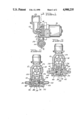
- FIG. 1 is a side elevational view in partial cross section, of a reversible pump arrangement embodying the invention
- FIG. 2 is a cross sectional view taken along the plane of the line 2--2 of FIG. 1, and looking in the direction of the arrows;
- FIG. 3 is a view similar to FIG. 2, showing a component thereof in a different operational condition.
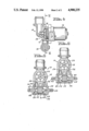
- FIG. 4 is a side elevational view in partial cross-section, of an alternate embodiment of the invention.
- FIG. 5 is a cross-sectional view taken along the plane of the line 5--5 of FIG. 4, and looking in the direction of the arrows;
- FIG. 6 is a view similar to FIG. 5, showing a component thereof in a different operational condition.
- FIG. 1 illustrates a reversible pump assembly 10 including an impeller housing 12, an outlet housing 14, and a motor housing 16.
- the impeller housing 12 includes a chamber 18 having an impeller 20 rotatably mounted therein, and an inlet passage 22 communicating with the chamber 18.
- a pair of outlet passages 24 and 26 lead from opposite sides of the impeller chamber 18 to a chamber 28 in the outlet housing 14.
- Oppositely disposed axially aligned tubular passages 30 and 32 extend from the chamber 28.
- the inner ends of the tubular passages 30 and 32 have respective chamfered ends 34 and 36 formed thereon.
- a cylindrical shaped piston 38 is slidably mounted in the chamber 28, intermediate the chamfered ends 34 and 36.
- the piston 38 includes conically shaped recesses 40 and 42 formed in opposite ends thereof, bottoming out in respective flat surfaces 44 and 46, on the centers of which respective bullet-nosed or substantially conically shaped projections 48 and 50 are formed for operative cooperation with the chamfered ends 34 and 36, as will be explained.
- the impeller 20 In operation, when activated in a clockwise direction (FIG. 2), the impeller 20 causes windshield washer fluid from the inlet passage 22 (FIG. 1) to be directed through the outlet passage 25 into the chamber 28, forcing the piston to move to the left in FIG. 2 until the projection 48 abuts against the chamfered end 34 of the tubular passage 30. This permits the fluid to be pumped through the tubular passage 32 to its intended destination, say, the front windshield.
- FIGS. 4 and 5 all elements identical to corresponding elements in FIGS. 1-3 bear the same reference numbers.
- a solid round piston 52 is slidably mounted in the chamber 28.
- Substantially cylindrical extensions 54 and 56 are formed on respective end faces 58 and 60 of the piston 52.
- Oppositely disposed axially aligned tubular passages 62 and 64 extend from the chamber 28.
- Chamfered edges 66 and 68 are formed on the respective inner ends of the tubular passages 62 and 64.
- An annular peripheral clearance 70 may be formed around the piston 52.
- FIGS. 4-6 arrangement The general operation of the FIGS. 4-6 arrangement is the same as for the FIGS. 1-3 arrangement, except that it is the distal end of the cylindrical extensions 54 and 56 which alternately abut against the respective chamfered edges 66 and 68 of the tubular passages 62 and 64 to permit fluid to be selectively pumped through one or the other of the tubular passages.
- the invention provides an improved pump and switching arrangement for a windshield and rear window washing system, including a slidably mounted piston of a particular configuration for effectively and efficiently selectively directing the fluid to either the windshield or rear window.
Landscapes
- Engineering & Computer Science (AREA)
- Mechanical Engineering (AREA)
- General Engineering & Computer Science (AREA)
- Water Supply & Treatment (AREA)
- Physics & Mathematics (AREA)
- Fluid Mechanics (AREA)
- Structures Of Non-Positive Displacement Pumps (AREA)
Abstract
Description
Claims (2)
Priority Applications (1)
| Application Number | Priority Date | Filing Date | Title |
|---|---|---|---|
| US07/308,059 US4900235A (en) | 1988-03-07 | 1989-02-09 | Reversible pump assembly |
Applications Claiming Priority (2)
| Application Number | Priority Date | Filing Date | Title |
|---|---|---|---|
| US07/164,833 US4824332A (en) | 1988-03-07 | 1988-03-07 | Reversible pump assembly |
| US07/308,059 US4900235A (en) | 1988-03-07 | 1989-02-09 | Reversible pump assembly |
Related Parent Applications (1)
| Application Number | Title | Priority Date | Filing Date |
|---|---|---|---|
| US07/164,833 Continuation-In-Part US4824332A (en) | 1988-03-07 | 1988-03-07 | Reversible pump assembly |
Publications (1)
| Publication Number | Publication Date |
|---|---|
| US4900235A true US4900235A (en) | 1990-02-13 |
Family
ID=26860894
Family Applications (1)
| Application Number | Title | Priority Date | Filing Date |
|---|---|---|---|
| US07/308,059 Expired - Lifetime US4900235A (en) | 1988-03-07 | 1989-02-09 | Reversible pump assembly |
Country Status (1)
| Country | Link |
|---|---|
| US (1) | US4900235A (en) |
Cited By (14)
| Publication number | Priority date | Publication date | Assignee | Title |
|---|---|---|---|---|
| US5071315A (en) * | 1989-07-31 | 1991-12-10 | Asmo Co., Ltd. | Windscreen washer pump for vehicle |
| US5186606A (en) * | 1989-04-29 | 1993-02-16 | Swf Auto-Electric Gmbh | Double feed pump, in particular for windshield washer systems in motor vehicles |
| US5486089A (en) * | 1994-02-28 | 1996-01-23 | Daewoo Electronics Co., Ltd. | Directional changeover pump |
| US5934872A (en) * | 1996-01-12 | 1999-08-10 | Jidosha Kenki Kogyo Kabushiki Kaisha | Washer pump for selectively supplying wash fluid to two areas |
| US5984644A (en) * | 1997-12-16 | 1999-11-16 | Ford Motor Company | Dual output window washer pump for an automotive vehicle |
| EP1120321A1 (en) * | 2000-01-28 | 2001-08-01 | Renault | Device for cleaning windscreen on automobile |
| US6461121B1 (en) * | 1998-07-08 | 2002-10-08 | Societe d'Etudes et de Realisations Industrielles et Commerciales “SERIC” | Monodirectional double outlet pump, and a system and method for washing automobile surfaces |
| US20060151532A1 (en) * | 2002-11-15 | 2006-07-13 | Rhea Vendors S.P.A. | Liquid supplying apparatus for vending machine |
| US20090114254A1 (en) * | 2007-11-05 | 2009-05-07 | Manuel Jeppe | Window cleaning system for windows of a motor vehicle |
| US20130126024A1 (en) * | 2011-11-17 | 2013-05-23 | Ryan P. Goss | Bi-Directional Pump |
| US20140166109A1 (en) * | 2010-10-05 | 2014-06-19 | Nifco Inc. | Fluid distribution valve, fluid supply system comprising same, and method for controlling the fluid supply system |
| US20140286747A1 (en) * | 2013-03-22 | 2014-09-25 | Johnson Electric S.A. | Pump having selectable outlets |
| US20160214577A1 (en) * | 2013-07-08 | 2016-07-28 | Mitsuba Corporation | Valve apparatus and washer apparatus |
| US20240026594A1 (en) * | 2020-12-15 | 2024-01-25 | Lg Electronics Inc. | Laundry treating apparatus |
Citations (9)
| Publication number | Priority date | Publication date | Assignee | Title |
|---|---|---|---|---|
| US1687523A (en) * | 1926-02-15 | 1928-10-16 | Edwin G Staude | Fluid-pressure pump for power-propelled vehicle-controlling means |
| US2567391A (en) * | 1946-06-27 | 1951-09-11 | Theodore E Mead | Exhaust valve structure |
| US2992652A (en) * | 1956-11-01 | 1961-07-18 | Louis F Guenther | Safety valve |
| US3753601A (en) * | 1971-08-09 | 1973-08-21 | J Hensley | Fluid actuated brake safety device |
| US4331295A (en) * | 1979-04-27 | 1982-05-25 | Hisanori Warihashi | Windshield washer |
| US4600361A (en) * | 1983-06-08 | 1986-07-15 | Strada Cantonale | Selectively controlled dual delivery pump, particularly for motor vehicle application |
| US4653977A (en) * | 1984-01-30 | 1987-03-31 | Flygt Aktienbolag | Pump for mixing and pumping liquids |
| US4679983A (en) * | 1983-05-11 | 1987-07-14 | Ford Motor Company | Water pump for window washer unit |
| US4728260A (en) * | 1986-04-30 | 1988-03-01 | Maruko Keihouki Kabushiki Kaisha | Direction-selectable sending-out pump |
-
1989
- 1989-02-09 US US07/308,059 patent/US4900235A/en not_active Expired - Lifetime
Patent Citations (9)
| Publication number | Priority date | Publication date | Assignee | Title |
|---|---|---|---|---|
| US1687523A (en) * | 1926-02-15 | 1928-10-16 | Edwin G Staude | Fluid-pressure pump for power-propelled vehicle-controlling means |
| US2567391A (en) * | 1946-06-27 | 1951-09-11 | Theodore E Mead | Exhaust valve structure |
| US2992652A (en) * | 1956-11-01 | 1961-07-18 | Louis F Guenther | Safety valve |
| US3753601A (en) * | 1971-08-09 | 1973-08-21 | J Hensley | Fluid actuated brake safety device |
| US4331295A (en) * | 1979-04-27 | 1982-05-25 | Hisanori Warihashi | Windshield washer |
| US4679983A (en) * | 1983-05-11 | 1987-07-14 | Ford Motor Company | Water pump for window washer unit |
| US4600361A (en) * | 1983-06-08 | 1986-07-15 | Strada Cantonale | Selectively controlled dual delivery pump, particularly for motor vehicle application |
| US4653977A (en) * | 1984-01-30 | 1987-03-31 | Flygt Aktienbolag | Pump for mixing and pumping liquids |
| US4728260A (en) * | 1986-04-30 | 1988-03-01 | Maruko Keihouki Kabushiki Kaisha | Direction-selectable sending-out pump |
Cited By (23)
| Publication number | Priority date | Publication date | Assignee | Title |
|---|---|---|---|---|
| US5186606A (en) * | 1989-04-29 | 1993-02-16 | Swf Auto-Electric Gmbh | Double feed pump, in particular for windshield washer systems in motor vehicles |
| US5071315A (en) * | 1989-07-31 | 1991-12-10 | Asmo Co., Ltd. | Windscreen washer pump for vehicle |
| US5486089A (en) * | 1994-02-28 | 1996-01-23 | Daewoo Electronics Co., Ltd. | Directional changeover pump |
| US5934872A (en) * | 1996-01-12 | 1999-08-10 | Jidosha Kenki Kogyo Kabushiki Kaisha | Washer pump for selectively supplying wash fluid to two areas |
| US5984644A (en) * | 1997-12-16 | 1999-11-16 | Ford Motor Company | Dual output window washer pump for an automotive vehicle |
| US6461121B1 (en) * | 1998-07-08 | 2002-10-08 | Societe d'Etudes et de Realisations Industrielles et Commerciales “SERIC” | Monodirectional double outlet pump, and a system and method for washing automobile surfaces |
| EP1120321A1 (en) * | 2000-01-28 | 2001-08-01 | Renault | Device for cleaning windscreen on automobile |
| FR2804396A1 (en) * | 2000-01-28 | 2001-08-03 | Renault | DEVICE FOR WASHING GLASS SURFACES FOR A MOTOR VEHICLE |
| US7624896B2 (en) * | 2002-11-15 | 2009-12-01 | Rhea Vendors S.P.A. | Liquid supplying apparatus for vending machine |
| US20060151532A1 (en) * | 2002-11-15 | 2006-07-13 | Rhea Vendors S.P.A. | Liquid supplying apparatus for vending machine |
| US20090114254A1 (en) * | 2007-11-05 | 2009-05-07 | Manuel Jeppe | Window cleaning system for windows of a motor vehicle |
| US20140166109A1 (en) * | 2010-10-05 | 2014-06-19 | Nifco Inc. | Fluid distribution valve, fluid supply system comprising same, and method for controlling the fluid supply system |
| US9261086B2 (en) * | 2010-10-05 | 2016-02-16 | Nifco Inc. | Fluid distribution valve, fluid supply system comprising same, and method for controlling the fluid supply system |
| US8894385B2 (en) * | 2011-11-17 | 2014-11-25 | Deere & Company | Bi-directional pump |
| CN103123040A (en) * | 2011-11-17 | 2013-05-29 | 迪尔公司 | Bi-directional pump |
| US20130126024A1 (en) * | 2011-11-17 | 2013-05-23 | Ryan P. Goss | Bi-Directional Pump |
| EP2594796A3 (en) * | 2011-11-17 | 2016-04-20 | Deere & Company | Bi-directional pump |
| CN103123040B (en) * | 2011-11-17 | 2016-08-31 | 迪尔公司 | Two-way pump |
| US20140286747A1 (en) * | 2013-03-22 | 2014-09-25 | Johnson Electric S.A. | Pump having selectable outlets |
| US9689403B2 (en) * | 2013-03-22 | 2017-06-27 | Johnson Electric S.A. | Pump having selectable outlets |
| US20160214577A1 (en) * | 2013-07-08 | 2016-07-28 | Mitsuba Corporation | Valve apparatus and washer apparatus |
| US9725075B2 (en) * | 2013-07-08 | 2017-08-08 | Mitsuba Corporation | Valve apparatus and washer apparatus |
| US20240026594A1 (en) * | 2020-12-15 | 2024-01-25 | Lg Electronics Inc. | Laundry treating apparatus |
Similar Documents
| Publication | Publication Date | Title |
|---|---|---|
| US4824332A (en) | Reversible pump assembly | |
| US4900235A (en) | Reversible pump assembly | |
| US4679983A (en) | Water pump for window washer unit | |
| EP0128446A1 (en) | Selectively controlled dual delivery pump, particularly for motor vehicle application | |
| US5213485A (en) | Air driven double diaphragm pump | |
| US4913401A (en) | Valve apparatus | |
| US2956586A (en) | Hose arrangement | |
| US5567118A (en) | Non-lubricated, air-actuated, pump-operating, shuttle valve arrangement, in a reciprocating pump | |
| US3730217A (en) | Check valve | |
| JPH0467039B2 (en) | ||
| US6749173B2 (en) | Valve arrangement and method of directing fluid flow | |
| US5344293A (en) | Double diaphragm leakproof sealing device for electric windscreen washer pumps | |
| US3985652A (en) | Dual coaxial bidirectional valves and filter assemblies and hydrostat systems containing the same | |
| EP0234802A2 (en) | Fluid pump | |
| US20030044285A1 (en) | Magnetic pumping system | |
| JPS63312589A (en) | Spool type directional control valve | |
| GB2317655A (en) | Reciprocating machine | |
| US5860797A (en) | Flow rate control device for a pump | |
| US4003397A (en) | Dual coaxial bidirectional valves and filter assemblies and hydrostat systems containing the same | |
| JPS62177379A (en) | Air pilot type passage switching valve | |
| GB1281657A (en) | Fluid-pressure-responsive logical elements | |
| US4531621A (en) | Flow control valve for fluid fan drive | |
| GB2052018A (en) | Non-return Valves | |
| US6478042B1 (en) | Valve, adapted to connect a flow module to a flow line | |
| KR200281968Y1 (en) | Vacuum connection pipe for vehicle brake booster |
Legal Events
| Date | Code | Title | Description |
|---|---|---|---|
| AS | Assignment |
Owner name: MCCORD WINN TEXTRON INC. Free format text: ASSIGNMENT OF ASSIGNORS INTEREST.;ASSIGNORS:PERKINS, JIMMIE G.;GRIM, JAMES W.;REEL/FRAME:005175/0772 Effective date: 19891016 |
|
| STCF | Information on status: patent grant |
Free format text: PATENTED CASE |
|
| FEPP | Fee payment procedure |
Free format text: PAYOR NUMBER ASSIGNED (ORIGINAL EVENT CODE: ASPN); ENTITY STATUS OF PATENT OWNER: LARGE ENTITY |
|
| FPAY | Fee payment |
Year of fee payment: 4 |
|
| FPAY | Fee payment |
Year of fee payment: 8 |
|
| FPAY | Fee payment |
Year of fee payment: 12 |
|
| AS | Assignment |
Owner name: CTEX SEAT COMFORT LIMITED, ENGLAND Free format text: ASSIGNMENT OF ASSIGNORS INTEREST;ASSIGNOR:MCCORD WINN TEXTRON INC.;REEL/FRAME:012906/0342 Effective date: 20001228 |