US4900143A - Ophthalmoscope handpiece with laser delivery system - Google Patents
Ophthalmoscope handpiece with laser delivery system Download PDFInfo
- Publication number
- US4900143A US4900143A US07/165,718 US16571888A US4900143A US 4900143 A US4900143 A US 4900143A US 16571888 A US16571888 A US 16571888A US 4900143 A US4900143 A US 4900143A
- Authority
- US
- United States
- Prior art keywords
- laser
- handpiece
- viewing aperture
- laser beam
- opening
- Prior art date
- Legal status (The legal status is an assumption and is not a legal conclusion. Google has not performed a legal analysis and makes no representation as to the accuracy of the status listed.)
- Expired - Fee Related
Links
- 230000008685 targeting Effects 0.000 claims abstract description 43
- 239000013307 optical fiber Substances 0.000 claims abstract description 20
- 230000008878 coupling Effects 0.000 claims abstract description 17
- 238000010168 coupling process Methods 0.000 claims abstract description 17
- 238000005859 coupling reaction Methods 0.000 claims abstract description 17
- 239000000835 fiber Substances 0.000 claims description 16
- 238000004891 communication Methods 0.000 claims description 5
- 238000010304 firing Methods 0.000 claims description 5
- 230000003287 optical effect Effects 0.000 claims description 5
- 230000004913 activation Effects 0.000 claims 1
- 238000001914 filtration Methods 0.000 claims 1
- 210000004220 fundus oculi Anatomy 0.000 abstract description 8
- 238000005286 illumination Methods 0.000 description 5
- 230000003902 lesion Effects 0.000 description 4
- 230000002207 retinal effect Effects 0.000 description 4
- 230000000994 depressogenic effect Effects 0.000 description 2
- 210000003128 head Anatomy 0.000 description 2
- 230000008439 repair process Effects 0.000 description 2
- 238000001356 surgical procedure Methods 0.000 description 2
- 206010038848 Retinal detachment Diseases 0.000 description 1
- 238000010276 construction Methods 0.000 description 1
- 230000003247 decreasing effect Effects 0.000 description 1
- 230000007547 defect Effects 0.000 description 1
- 230000000694 effects Effects 0.000 description 1
- 238000004519 manufacturing process Methods 0.000 description 1
- 238000012986 modification Methods 0.000 description 1
- 230000004048 modification Effects 0.000 description 1
- 210000001747 pupil Anatomy 0.000 description 1
- 230000000246 remedial effect Effects 0.000 description 1
- 230000004242 retinal defects Effects 0.000 description 1
Images

Classifications
-
- A—HUMAN NECESSITIES
- A61—MEDICAL OR VETERINARY SCIENCE; HYGIENE
- A61B—DIAGNOSIS; SURGERY; IDENTIFICATION
- A61B3/00—Apparatus for testing the eyes; Instruments for examining the eyes
- A61B3/10—Objective types, i.e. instruments for examining the eyes independent of the patients' perceptions or reactions
- A61B3/12—Objective types, i.e. instruments for examining the eyes independent of the patients' perceptions or reactions for looking at the eye fundus, e.g. ophthalmoscopes
- A61B3/1225—Objective types, i.e. instruments for examining the eyes independent of the patients' perceptions or reactions for looking at the eye fundus, e.g. ophthalmoscopes using coherent radiation
Definitions
- This invention relates to an ophthalmoscope handpiece with a laser delivery system for viewing the fundus oculi and delivering a remedial laser beam to the fundus.
- the handpiece includes a magnifying lens for providing a magnified view of the fundus, and laser delivery means for selectively directing a laser beam to the fundus.
- Ophthalmoscopes have long been used by oculists for viewing the fundus of the eye. Often a binocular indirect ophthalmoscope, which provides a stereoscopic view of the fundus, is used in conjunction with an ophthalmoscope handpiece which contains a magnifying lens which magnifies the oculist's view of the fundus oculi. Such handpieces can be easily positioned to survey the fundus from various angles such that a more comprehensive examination can be made. In addition to their diagnostic applications, in recent years ophthalmoscopes have been used to assist in the targeting of lasers used to correct retinal defects such as detached retinas. For example, U.S. Letters Patent No.
- 4,477,159 discloses a system which utilizes an ophthalmoscope to assist in the targeting of retinal lesions and which directs a laser beam to the targeted lesion.
- the patient's head is immobilized and a binocular indirect ophthalmoscope is used for viewing the fundus during targeting.
- the laser is fired from a delivery system mounted on or proximate the binocular ophthalmoscope.
- the binocular indirect ophthalmoscope the mobility of the delivery system is greatly decreased, and targeting of the laser can be difficult and time consuming.
- targeting of lesions located in the periphery of the fundus can be particularly difficult.
- Pat. No. 4,477,159 attempts to add mobility by placing the laser delivery means on a binocular indirect ophthalmoscope.
- targeting can still be difficult, particularly due to the inability to bring the delivery means in close proximity to the eye.
- small movements of the oculist's head or the patient's eye result in large targeting errors.
- Other related prior art is disclosed by U.S. Letters Pat. Nos. 4,582,405; 4,669,837; 4,669,839; 4,684,227; and 4,699,480.
- an ophthalmoscope handpiece with a laser delivery system for viewing the fundus oculi and delivering a laser beam to the fundus.
- Another object of the present invention is to provide an ophthalmoscope handpiece with laser delivery means which is highly mobile such that laser targeting is more accurate and more easily accomplished.
- Yet a further object of the present invention is to provide an ophthalmoscope handpiece which carries a laser delivery means which can be placed in close proximity to the eye so as to reduce targeting errors.
- Another object of the present invention is to provide an ophthalmoscope handpiece with a laser delivery system which is inexpensive to manufacture and maintain.
- the present invention provides an ophthalmoscope handpiece for viewing the fundus of the eye and for delivering a laser beam and laser targeting beam to the fundus to effect retinal repairs and for performing other ocular surgical procedures.
- the handpiece comprises a body having first and second end portions and having a viewing aperture therethrough so as to define a first opening at the first end portion and a second opening at the second end portion.
- the handpiece is provided with magnifying means, including a magnifying lens mounted in the viewing aperture for providing a magnified view of the fundus.
- An optical fiber coupling assembly is provided for connecting the handpiece to an optical fiber which communicates a laser targeting beam and a laser beam to the handpiece.
- the coupling assembly is received in a receptor provided in the body of the handpiece such that the targeting beam and the laser beam are selectively directed into the viewing aperture of the handpiece.
- Beam deflecting means mounted within the viewing aperture, selectively intercept the laser beam and targeting beam and redirect the beams through the first opening of the handpiece such that the beams can be directed to the fundus of the eye.
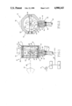
- FIG. 1 illustrates a side elevation view, in section, of an ophthalmoscope handpiece of the present invention
- FIG. 2 illustrates a front view, in section, of an ophthalmoscope handpiece of the present invention
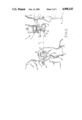
- FIG. 3 illustrates a side view of an ophthalmoscope handpiece of the present invention being used by an oculist to examine the fundus of a patient's eye;
- FIG. 4 illustrates a front view of a binocular indirect ophthalmoscope filter means of the present invention.
- an ophthalmoscope handpiece incorporating various features of the present invention is illustrated generally at 10 in the figures.
- the handpiece 10 is used by an oculist to examine the fundus oculi and to target and deliver a laser beam for effecting retinal repairs and for performing other ocular surgical procedures.
- the handpiece 10 is generally used in conjunction with a binocular indirect ophthalmoscope 12 (See FIGS. 3 and 4) which allows the fundus to be stereoscopically viewed by the oculist.
- the ophthalmoscope 12 comprises illumination means 14 which directs light through a light aperture 16 and into the eye 18 of the patient through the pupil of the eye.
- the light is reflected by the fundus and the reflected light is received through the optical aperture 20 of the ophthalmoscope.
- the reflected light received through the aperture 20 is then directed to a pair of eyepieces 22 by certain mirrors or reflective surfaces (not shown) to be perceived by the oculist 24 in the form of a stereoscopic view of the fundus oculi.
- the ophthalmoscope handpiece 10 generally comprises a body 26 defining first and second end portions 28 and 30, respectively, and having a viewing aperture 32 therethrough such that first an second openings 34 and 36 are defined at the first and second end portions 28 and 30, respectively.
- the handpiece 10 further comprises magnifying means which in the preferred embodiment comprises a magnifying lens 38 mounted within the viewing aperture 32. More specifically, the lens 38 is releasably received in a circumferential lens seat 40 provided in the interior walls of the aperture 32, and such interior walls define a threaded portion 42 between the lens seat 40 and the opening 36 for threadably receiving a lens retaining ring 44 which releasably holds the lens 38 in position.
- the lens 38 provides the oculist with a magnified view of the fundus to facilitate location of retinal lesions or other defects of the fundus oculi.
- the ophthalmoscope handpiece 10 also comprises laser delivery means including an optical fiber coupling assembly 46, and beam deflecting means 48.
- the coupling assembly 46 serves as a means for connecting the handpiece 10 to an optical fiber 50.
- the optical fiber 50 is connected to a suitable laser generating means 51 and to a further illumination means 53 which, as will be discussed below, produces a narrow beam of light for targeting the laser beam (See FIG. 1).
- the coupling assembly 46 comprises a housing 52 defining first and second end portions 54 and 56, respectively, the first end portion 54 being threadably received in a receptor 58 provided in the body 26.
- a beam passage 60 extends through the housing 52 from the first end portion 54 to the second end portion 56.
- the passageway defines a further lens seat 62 for receiving a fiber focusing lens 64, and at the second end portion 54 a fiber optic connector 66 is provided for connecting the optical fiber 50 to the housing 52, thereby placing the passage 60 in communication with the fiber 50.
- a fiber optic connector 66 is provided for connecting the optical fiber 50 to the housing 52, thereby placing the passage 60 in communication with the fiber 50.
- the fiber coupling assembly 46 is oriented such that the common path, illustrated at 67, of the laser beam and laser targeting beam, is substantially perpendicular to the axis 65 of the viewing aperture 32.
- the handpiece 10 is provided with the above-referenced beam deflection means 48.
- the deflection means 48 comprises a transparent member 68 pivotally mounted in the handpiece 10 so as to bisect the viewing aperture 32.
- the transparent member 68 defines a forward surface 70 carrying a centrally disposed reflective surface portion 72 which intercepts the targeting beam and the laser beam at, or proximate, the axis of the aperture 32.
- the transparent member 68 is pivotally secured at its opposite ends to the body 26 of the handpiece 10 such that the reflective surface portion 72 can be positioned at substantially a forty-five (45) degree angle to the axis of the aperture 32 such that the targeting and laser beams are redirected to a path substantially coaxial with the aperture 32.
- the pivotal mounting of the transparent member 68 allows the angle of the reflective surface portion 72 to be adjusted and, thus, the exit path of the laser and targeting beams to be adjusted.
- the transparent member 68, with its reflective surface portion 72 merely represents one preferred beam deflection means, and it is contemplated that other suitable means can be utilized for redirecting the laser and laser targeting beams if desired.
- the handpiece 10 when in use, the handpiece 10 is held in front of the patient's eye 18 and with the aid of the binocular ophthalmoscope 12, the oculist 24 views (along sight line 73) the fundus through the magnifying lens 38 of the handpiece 10, with the illumination means 14 of the binocular ophthalmoscope 12 providing the necessary illumination for viewing.
- the narrow targeting beam generated by the further illumination means 53, and communicated to the handpiece 10 by the fiber 50 reflects off of the fundus so as to provide an illuminated spot on the fundus where the laser beam will strike when fired.
- the laser is targeted by manipulating the handpiece 10 to place the illuminated spot produced by the targeting beam at the location at which laser impact is desired.
- the laser is fired by a suitable laser actuating means such as the foot pedal 74 (See FIG. 1).
- a suitable laser actuating means such as the foot pedal 74 (See FIG. 1).
- the handpiece can optionally be provided with a safety switch 76, connected to the laser generating means 51 by conventional circuitry, which must be manually depressed, or otherwise actuated by the oculist, before the laser actuator means, i.e., the pedal 74, will fire the laser.
- a safety switch 76 connected to the laser generating means 51 by conventional circuitry, which must be manually depressed, or otherwise actuated by the oculist, before the laser actuator means, i.e., the pedal 74, will fire the laser.
- a filter means 82 is provided for mounting on the binocular ophthalmoscope 12 to filter out laser reflection.
- the filter means 82 comprises a filter actuator 84 secured to the ophthalmoscope 12 and provided with a pivoting actuator arm 86 which carries a filter panel 88.
- the actuator 84 is connected by conventional circuitry, including switching means, to the laser generating means 51 such that as the foot pedal 74 is depressed, the actuator 84 pivots the actuator arm 86 so as to place the filter panel 88 in front of the optical aperture 20 of the ophthalmoscope 12. And, only when the filter panel 88 is in place in front of the aperture 20 does the switching means allow the laser to fire.
- the ophthalmoscope handpiece 10 with its laser delivery system provides great advantages over the prior art.
- the laser delivery system is highly mobile, and, in fact, can be wielded by the oculist much like a scalpel. Also, the ability to bring the point of laser delivery in close proximity to the patient's eye enhances targeting accuracy and allows better access to the periphery of the fundus.
Abstract
Description
Claims (7)
Priority Applications (1)
| Application Number | Priority Date | Filing Date | Title |
|---|---|---|---|
| US07/165,718 US4900143A (en) | 1988-03-09 | 1988-03-09 | Ophthalmoscope handpiece with laser delivery system |
Applications Claiming Priority (1)
| Application Number | Priority Date | Filing Date | Title |
|---|---|---|---|
| US07/165,718 US4900143A (en) | 1988-03-09 | 1988-03-09 | Ophthalmoscope handpiece with laser delivery system |
Publications (1)
| Publication Number | Publication Date |
|---|---|
| US4900143A true US4900143A (en) | 1990-02-13 |
Family
ID=22600156
Family Applications (1)
| Application Number | Title | Priority Date | Filing Date |
|---|---|---|---|
| US07/165,718 Expired - Fee Related US4900143A (en) | 1988-03-09 | 1988-03-09 | Ophthalmoscope handpiece with laser delivery system |
Country Status (1)
| Country | Link |
|---|---|
| US (1) | US4900143A (en) |
Cited By (26)
| Publication number | Priority date | Publication date | Assignee | Title |
|---|---|---|---|---|
| US5339120A (en) * | 1992-11-16 | 1994-08-16 | Oglesby Jr Frank L | Retina evaluation reticle apparatus |
| US5400092A (en) * | 1991-12-17 | 1995-03-21 | Mira, Inc. | Binocular ophthalmoscope |
| US5413555A (en) * | 1993-04-30 | 1995-05-09 | Mcmahan; William H. | Laser delivery system |
| US20040199149A1 (en) * | 1996-03-21 | 2004-10-07 | Myers Raymond I. | Lenticular refractive surgery of presbyopia, other refractive errors, and cataract retardation |
| WO2005077308A1 (en) | 2004-01-14 | 2005-08-25 | Optical System & Research For Industry And Science Osyris | Apparatus and method for treating corneal neovascularization or blood vessel accumulation on the conjunctiva |
| US20070173794A1 (en) * | 2006-01-20 | 2007-07-26 | Frey Rudolph W | System and method for treating the structure of the human lens with a laser |
| EP1872753A1 (en) * | 2006-06-30 | 2008-01-02 | Alcon, Inc. | Multifunction surgical probe |
| US20100004643A1 (en) * | 2006-01-20 | 2010-01-07 | Frey Rudolph W | System and method for improving the accommodative amplitude and increasing the refractive power of the human lens with a laser |
| US20100022995A1 (en) * | 2008-07-25 | 2010-01-28 | Frey Rudolph W | Method and system for removal and replacement of lens material from the lens of an eye |
| US20100022994A1 (en) * | 2008-07-25 | 2010-01-28 | Frey Rudolph W | Liquid filled index matching device for ophthalmic laser procedures |
| US20100022996A1 (en) * | 2008-07-25 | 2010-01-28 | Frey Rudolph W | Method and system for creating a bubble shield for laser lens procedures |
| US20100292678A1 (en) * | 2006-01-20 | 2010-11-18 | Frey Rudolph W | System and method for providing laser shot patterns to the lens of an eye |
| US20110022036A1 (en) * | 2009-07-24 | 2011-01-27 | Frey Rudolph W | System and method for performing ladar assisted procedures on the lens of an eye |
| US20110022035A1 (en) * | 2009-07-24 | 2011-01-27 | Porter Gerrit N | Liquid holding interface device for ophthalmic laser procedures |
| US20110160710A1 (en) * | 2009-07-24 | 2011-06-30 | Frey Rudolph W | Laser system and method for performing and sealing corneal incisions in the eye |
| US20110166557A1 (en) * | 2009-07-24 | 2011-07-07 | Naranjo-Tackman Ramon | Laser system and method for astigmatic corrections in asssociation with cataract treatment |
| US20110190740A1 (en) * | 2010-02-01 | 2011-08-04 | Lensar, Inc. | Placido ring measurement of astigmatism axis and laser marking of astigmatism axis |
| US8262646B2 (en) | 2006-01-20 | 2012-09-11 | Lensar, Inc. | System and method for providing the shaped structural weakening of the human lens with a laser |
| US8556425B2 (en) | 2010-02-01 | 2013-10-15 | Lensar, Inc. | Purkinjie image-based alignment of suction ring in ophthalmic applications |
| USD694890S1 (en) | 2010-10-15 | 2013-12-03 | Lensar, Inc. | Laser system for treatment of the eye |
| USD695408S1 (en) | 2010-10-15 | 2013-12-10 | Lensar, Inc. | Laser system for treatment of the eye |
| US8617146B2 (en) | 2009-07-24 | 2013-12-31 | Lensar, Inc. | Laser system and method for correction of induced astigmatism |
| US8801186B2 (en) | 2010-10-15 | 2014-08-12 | Lensar, Inc. | System and method of scan controlled illumination of structures within an eye |
| US9393154B2 (en) | 2011-10-28 | 2016-07-19 | Raymond I Myers | Laser methods for creating an antioxidant sink in the crystalline lens for the maintenance of eye health and physiology and slowing presbyopia development |
| US9889043B2 (en) | 2006-01-20 | 2018-02-13 | Lensar, Inc. | System and apparatus for delivering a laser beam to the lens of an eye |
| US10463541B2 (en) | 2011-03-25 | 2019-11-05 | Lensar, Inc. | System and method for correcting astigmatism using multiple paired arcuate laser generated corneal incisions |
Citations (2)
| Publication number | Priority date | Publication date | Assignee | Title |
|---|---|---|---|---|
| US3583795A (en) * | 1968-07-17 | 1971-06-08 | Optotechnik Gmbh | Optical systems for ophthalmoscopes |
| US3698099A (en) * | 1971-01-29 | 1972-10-17 | American Optical Corp | Ophthalmoscopes |
-
1988
- 1988-03-09 US US07/165,718 patent/US4900143A/en not_active Expired - Fee Related
Patent Citations (2)
| Publication number | Priority date | Publication date | Assignee | Title |
|---|---|---|---|---|
| US3583795A (en) * | 1968-07-17 | 1971-06-08 | Optotechnik Gmbh | Optical systems for ophthalmoscopes |
| US3698099A (en) * | 1971-01-29 | 1972-10-17 | American Optical Corp | Ophthalmoscopes |
Cited By (42)
| Publication number | Priority date | Publication date | Assignee | Title |
|---|---|---|---|---|
| US5400092A (en) * | 1991-12-17 | 1995-03-21 | Mira, Inc. | Binocular ophthalmoscope |
| US5339120A (en) * | 1992-11-16 | 1994-08-16 | Oglesby Jr Frank L | Retina evaluation reticle apparatus |
| US5413555A (en) * | 1993-04-30 | 1995-05-09 | Mcmahan; William H. | Laser delivery system |
| US7655002B2 (en) | 1996-03-21 | 2010-02-02 | Second Sight Laser Technologies, Inc. | Lenticular refractive surgery of presbyopia, other refractive errors, and cataract retardation |
| US20040199149A1 (en) * | 1996-03-21 | 2004-10-07 | Myers Raymond I. | Lenticular refractive surgery of presbyopia, other refractive errors, and cataract retardation |
| US20100114079A1 (en) * | 1996-03-21 | 2010-05-06 | Second Sight Laser Technologies, Inc. | Lenticular refractive surgery of presbyopia, other refractive errors, and cataract retardation |
| WO2005077308A1 (en) | 2004-01-14 | 2005-08-25 | Optical System & Research For Industry And Science Osyris | Apparatus and method for treating corneal neovascularization or blood vessel accumulation on the conjunctiva |
| US9889043B2 (en) | 2006-01-20 | 2018-02-13 | Lensar, Inc. | System and apparatus for delivering a laser beam to the lens of an eye |
| US20070173794A1 (en) * | 2006-01-20 | 2007-07-26 | Frey Rudolph W | System and method for treating the structure of the human lens with a laser |
| US20100004643A1 (en) * | 2006-01-20 | 2010-01-07 | Frey Rudolph W | System and method for improving the accommodative amplitude and increasing the refractive power of the human lens with a laser |
| US9180051B2 (en) | 2006-01-20 | 2015-11-10 | Lensar Inc. | System and apparatus for treating the lens of an eye |
| US8262646B2 (en) | 2006-01-20 | 2012-09-11 | Lensar, Inc. | System and method for providing the shaped structural weakening of the human lens with a laser |
| US9375349B2 (en) | 2006-01-20 | 2016-06-28 | Lensar, Llc | System and method for providing laser shot patterns to the lens of an eye |
| US9545338B2 (en) | 2006-01-20 | 2017-01-17 | Lensar, Llc. | System and method for improving the accommodative amplitude and increasing the refractive power of the human lens with a laser |
| US10842675B2 (en) | 2006-01-20 | 2020-11-24 | Lensar, Inc. | System and method for treating the structure of the human lens with a laser |
| US20070173795A1 (en) * | 2006-01-20 | 2007-07-26 | Frey Rudolph W | System and apparatus for treating the lens of an eye |
| US20100292678A1 (en) * | 2006-01-20 | 2010-11-18 | Frey Rudolph W | System and method for providing laser shot patterns to the lens of an eye |
| EP1872753A1 (en) * | 2006-06-30 | 2008-01-02 | Alcon, Inc. | Multifunction surgical probe |
| US20080004608A1 (en) * | 2006-06-30 | 2008-01-03 | Alcon, Inc. | Multifunction surgical probe |
| US20100042079A1 (en) * | 2008-07-25 | 2010-02-18 | Frey Rudolph W | Method and System for Removal and Replacement of Lens Material fron the Lens of an Eye |
| US8500723B2 (en) | 2008-07-25 | 2013-08-06 | Lensar, Inc. | Liquid filled index matching device for ophthalmic laser procedures |
| US20100022996A1 (en) * | 2008-07-25 | 2010-01-28 | Frey Rudolph W | Method and system for creating a bubble shield for laser lens procedures |
| US20100022994A1 (en) * | 2008-07-25 | 2010-01-28 | Frey Rudolph W | Liquid filled index matching device for ophthalmic laser procedures |
| US20100022995A1 (en) * | 2008-07-25 | 2010-01-28 | Frey Rudolph W | Method and system for removal and replacement of lens material from the lens of an eye |
| US8708491B2 (en) | 2008-07-25 | 2014-04-29 | Lensar, Inc. | Method and system for measuring an eye |
| US8480659B2 (en) | 2008-07-25 | 2013-07-09 | Lensar, Inc. | Method and system for removal and replacement of lens material from the lens of an eye |
| US20110166557A1 (en) * | 2009-07-24 | 2011-07-07 | Naranjo-Tackman Ramon | Laser system and method for astigmatic corrections in asssociation with cataract treatment |
| US20110160710A1 (en) * | 2009-07-24 | 2011-06-30 | Frey Rudolph W | Laser system and method for performing and sealing corneal incisions in the eye |
| US20110022036A1 (en) * | 2009-07-24 | 2011-01-27 | Frey Rudolph W | System and method for performing ladar assisted procedures on the lens of an eye |
| US20110022035A1 (en) * | 2009-07-24 | 2011-01-27 | Porter Gerrit N | Liquid holding interface device for ophthalmic laser procedures |
| US8617146B2 (en) | 2009-07-24 | 2013-12-31 | Lensar, Inc. | Laser system and method for correction of induced astigmatism |
| US8465478B2 (en) | 2009-07-24 | 2013-06-18 | Lensar, Inc. | System and method for performing LADAR assisted procedures on the lens of an eye |
| US8758332B2 (en) | 2009-07-24 | 2014-06-24 | Lensar, Inc. | Laser system and method for performing and sealing corneal incisions in the eye |
| US8382745B2 (en) | 2009-07-24 | 2013-02-26 | Lensar, Inc. | Laser system and method for astigmatic corrections in association with cataract treatment |
| US8556425B2 (en) | 2010-02-01 | 2013-10-15 | Lensar, Inc. | Purkinjie image-based alignment of suction ring in ophthalmic applications |
| US20110190740A1 (en) * | 2010-02-01 | 2011-08-04 | Lensar, Inc. | Placido ring measurement of astigmatism axis and laser marking of astigmatism axis |
| US8801186B2 (en) | 2010-10-15 | 2014-08-12 | Lensar, Inc. | System and method of scan controlled illumination of structures within an eye |
| USD695408S1 (en) | 2010-10-15 | 2013-12-10 | Lensar, Inc. | Laser system for treatment of the eye |
| USD694890S1 (en) | 2010-10-15 | 2013-12-03 | Lensar, Inc. | Laser system for treatment of the eye |
| US10463541B2 (en) | 2011-03-25 | 2019-11-05 | Lensar, Inc. | System and method for correcting astigmatism using multiple paired arcuate laser generated corneal incisions |
| US9393154B2 (en) | 2011-10-28 | 2016-07-19 | Raymond I Myers | Laser methods for creating an antioxidant sink in the crystalline lens for the maintenance of eye health and physiology and slowing presbyopia development |
| US9937078B2 (en) | 2011-10-28 | 2018-04-10 | Raymond I Myers | Laser methods for creating an antioxidant sink in the crystalline lens for the maintenance of eye health and physiology and slowing presbyopia development |
Similar Documents
| Publication | Publication Date | Title |
|---|---|---|
| US4900143A (en) | Ophthalmoscope handpiece with laser delivery system | |
| US5997141A (en) | System for treating the fundus of an eye | |
| US5126877A (en) | Illumination system for a surgical microscope | |
| US4582405A (en) | Ophthalmological combination instrument for diagnosis and treatment | |
| US4477159A (en) | Photocoagulator | |
| US6096028A (en) | Multi-slot laser surgery | |
| US5295989A (en) | Light cable for use in an apparatus for ophthalmic operation using a laser beam | |
| US4779968A (en) | Coaxial illuminating system for operation microscopes | |
| EP2012696B1 (en) | Dynamic optical surgical system utilizing a fixed relationship between target tissue visualization and beam delivery | |
| US4565197A (en) | Laser ophthalmic surgical system | |
| KR101862809B1 (en) | White coherent laser light launched into nano fibers for surgical illumination | |
| US5252999A (en) | Laser apparatus including binocular indirect ophthalmoscope | |
| US5537164A (en) | Retroilluminating indirect gonioprism | |
| JPH04244151A (en) | Laser operation apparatus for ophthalmology | |
| US5283598A (en) | Illumination of the cornea for profilometry | |
| JPH1099281A (en) | Ophthalmic observation device | |
| JPH0348807B2 (en) | ||
| US5101826A (en) | Noncontact type tonometer | |
| US11957412B2 (en) | Imaging device for ophthalmic laser system using off-axis miniature camera | |
| JP2892007B2 (en) | Non-contact tonometer | |
| US6830335B2 (en) | Ophthalmoscope laser attachment | |
| US20210275017A1 (en) | Imaging device for ophthalmic laser system using off-axis miniature camera | |
| EP3214994B1 (en) | Lens system for inspection of an eye | |
| JPS61226016A (en) | Non-contact type tonometer | |
| JP2024047996A (en) | Light source device for ophthalmic device and ophthalmic device |
Legal Events
| Date | Code | Title | Description |
|---|---|---|---|
| AS | Assignment |
Owner name: ELECTRO-OPTICS LABORATORY, INC., COUNTY OF KNOX, T Free format text: ASSIGNMENT OF ASSIGNORS INTEREST.;ASSIGNORS:BESSLER, MICHAEL;HUTCHINSON, DONALD P.;REEL/FRAME:004872/0632 Effective date: 19880302 Owner name: ELECTRO-OPTICS LABORATORY, INC., A TN CORP.,TENNES Free format text: ASSIGNMENT OF ASSIGNORS INTEREST;ASSIGNORS:BESSLER, MICHAEL;HUTCHINSON, DONALD P.;REEL/FRAME:004872/0632 Effective date: 19880302 |
|
| REMI | Maintenance fee reminder mailed | ||
| LAPS | Lapse for failure to pay maintenance fees | ||
| FP | Lapsed due to failure to pay maintenance fee |
Effective date: 19940213 |
|
| STCH | Information on status: patent discontinuation |
Free format text: PATENT EXPIRED DUE TO NONPAYMENT OF MAINTENANCE FEES UNDER 37 CFR 1.362 |