US4900063A - Clamping connection unit - Google Patents
Clamping connection unit Download PDFInfo
- Publication number
- US4900063A US4900063A US07/311,984 US31198489A US4900063A US 4900063 A US4900063 A US 4900063A US 31198489 A US31198489 A US 31198489A US 4900063 A US4900063 A US 4900063A
- Authority
- US
- United States
- Prior art keywords
- coupling
- pipes
- coupling halves
- internal
- chamfered
- Prior art date
- Legal status (The legal status is an assumption and is not a legal conclusion. Google has not performed a legal analysis and makes no representation as to the accuracy of the status listed.)
- Expired - Lifetime
Links
Images
Classifications
-
- F—MECHANICAL ENGINEERING; LIGHTING; HEATING; WEAPONS; BLASTING
- F16—ENGINEERING ELEMENTS AND UNITS; GENERAL MEASURES FOR PRODUCING AND MAINTAINING EFFECTIVE FUNCTIONING OF MACHINES OR INSTALLATIONS; THERMAL INSULATION IN GENERAL
- F16L—PIPES; JOINTS OR FITTINGS FOR PIPES; SUPPORTS FOR PIPES, CABLES OR PROTECTIVE TUBING; MEANS FOR THERMAL INSULATION IN GENERAL
- F16L23/00—Flanged joints
- F16L23/02—Flanged joints the flanges being connected by members tensioned axially
- F16L23/024—Flanged joints the flanges being connected by members tensioned axially characterised by how the flanges are joined to, or form an extension of, the pipes
- F16L23/028—Flanged joints the flanges being connected by members tensioned axially characterised by how the flanges are joined to, or form an extension of, the pipes the flanges being held against a shoulder
- F16L23/0286—Flanged joints the flanges being connected by members tensioned axially characterised by how the flanges are joined to, or form an extension of, the pipes the flanges being held against a shoulder the shoulder not being formed from the pipe
-
- F—MECHANICAL ENGINEERING; LIGHTING; HEATING; WEAPONS; BLASTING
- F16—ENGINEERING ELEMENTS AND UNITS; GENERAL MEASURES FOR PRODUCING AND MAINTAINING EFFECTIVE FUNCTIONING OF MACHINES OR INSTALLATIONS; THERMAL INSULATION IN GENERAL
- F16L—PIPES; JOINTS OR FITTINGS FOR PIPES; SUPPORTS FOR PIPES, CABLES OR PROTECTIVE TUBING; MEANS FOR THERMAL INSULATION IN GENERAL
- F16L23/00—Flanged joints
- F16L23/04—Flanged joints the flanges being connected by members tensioned in the radial plane
- F16L23/08—Flanged joints the flanges being connected by members tensioned in the radial plane connection by tangentially arranged pin and nut
- F16L23/10—Flanged joints the flanges being connected by members tensioned in the radial plane connection by tangentially arranged pin and nut with a pivoting or swinging pin
-
- Y—GENERAL TAGGING OF NEW TECHNOLOGICAL DEVELOPMENTS; GENERAL TAGGING OF CROSS-SECTIONAL TECHNOLOGIES SPANNING OVER SEVERAL SECTIONS OF THE IPC; TECHNICAL SUBJECTS COVERED BY FORMER USPC CROSS-REFERENCE ART COLLECTIONS [XRACs] AND DIGESTS
- Y10—TECHNICAL SUBJECTS COVERED BY FORMER USPC
- Y10S—TECHNICAL SUBJECTS COVERED BY FORMER USPC CROSS-REFERENCE ART COLLECTIONS [XRACs] AND DIGESTS
- Y10S285/00—Pipe joints or couplings
- Y10S285/917—Metallic seals
Definitions
- This invention relates to a clamping connection unit for releasably clamping together two cylindrical pipes, comprising two abutting coupling halves, one at each pipe end, an elastic sealing ring (O-ring) placed between them and a clamping connection pressing the two coupling halves together.
- a clamping connection unit for releasably clamping together two cylindrical pipes, comprising two abutting coupling halves, one at each pipe end, an elastic sealing ring (O-ring) placed between them and a clamping connection pressing the two coupling halves together.
- the flange connection between the pipes must be absolutely tight to ensure that the sealing material will not be damaged and dead spaces must be avoided at the flange connections because they would act as harbouring places for the formation of deposits or decomposition products which could give rise to manufacturing breakdown, for example due to the blockage of filters.
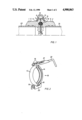
- FIG. 1 is a section through a coupling wall with the clamping connection unit according to the invention and pipe ends inserted in position
- FIG. 2 is a view in perspective of a conventional commercial form of clamping connection
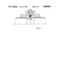
- FIG. 3 shows another embodiment of a clamping connection unit.
- each coupling wall has a circular cylindrical annular groove (17,18) situated between the internal surfaces (3,4) and the external surface (5,6) on the otherwise smooth end face.
- each groove is V-shaped so that an annular gap which is rectangular in cross-section is formed between the two coupling halves or pipe ends, but the edges of the cross-section at the centre of the coupling halves may be rounded off.
- An O-ring (16) is inserted as sealing ring in this gap.
- the pipe ends (23,24) are fitted into corresponding circular cylindrical recesses on the internal surface of the coupling halves.
- the internal diameters of the pipes have the same diameter as the abutting internal surfaces 3,4 of the coupling halves so that all the internal walls are smoothly adjoining.
- the coupling halves On the side situated externally to the pipes, the coupling halves have annular ridges (7,8).
- the adjacent surfaces (9,10) of these ridges extend radially while the surfaces (11,12) facing away from one another are chamfered off.
- the clamping connection is formed by a conventional commercial pipe clamp (15) shown in FIG. 2.
- a conventional commercial pipe clamp 15 shown in FIG. 2.
- it comprises two clamping jaws (13,14), each in the form of a half ring, with the internal surfaces chamfered off in the form of a V conforming to the chamfered surfaces (11,12) of the aforesaid ridges.
- Each end of the half ring of the jaw is curved in the form of a hook (19) or eye and two adjacent curved ends are held together by joint clamps (20,21).
- One of the joint clamps preferably has a bore with a screw thread at one end in which a screw (22) may be turned to press against the curved end (19) to produce the clamping connection.
- each coupling half may have a trough-shaped recess (25,26) extending in the axial direction from the ridges (7,8) to receive the ends of the clamping jaws when the two halves are pressed together, as shown in FIG. 3.
- the internal surfaces of the clamping jaws are chamfered off so that they are V-shaped in section to conform to the chamfered surfaces of the ridges so that the coupling halves can be pressed together under a uniform pressure extending over the whole annular surface of the ridges.
- the two coupling halves are centered by an O-ring fitted into a special double V-shaped O-ring recess,
- the metallic sealing surfaces are only in contact with each other on the internal contacting surfaces 27 and 28 of the coupling, through which the liquid is transported, so that no elastic sealing material will come into direct contact with the liquid,
- the clamping connection unit is easy to clean by virtue of its special design
- the seal may be used both under conditions of excess pressure and under a vacuum.
Abstract
Description
Claims (3)
Applications Claiming Priority (2)
| Application Number | Priority Date | Filing Date | Title |
|---|---|---|---|
| DE3806630 | 1988-03-02 | ||
| DE3806630A DE3806630A1 (en) | 1988-03-02 | 1988-03-02 | CLAMP CONNECTION UNIT |
Publications (1)
| Publication Number | Publication Date |
|---|---|
| US4900063A true US4900063A (en) | 1990-02-13 |
Family
ID=6348563
Family Applications (1)
| Application Number | Title | Priority Date | Filing Date |
|---|---|---|---|
| US07/311,984 Expired - Lifetime US4900063A (en) | 1988-03-02 | 1989-02-16 | Clamping connection unit |
Country Status (4)
| Country | Link |
|---|---|
| US (1) | US4900063A (en) |
| EP (1) | EP0330946B1 (en) |
| JP (1) | JP2857404B2 (en) |
| DE (2) | DE3806630A1 (en) |
Cited By (14)
| Publication number | Priority date | Publication date | Assignee | Title |
|---|---|---|---|---|
| US5429397A (en) * | 1990-07-26 | 1995-07-04 | Kanao; Shiro | Corrugated pipe with joint and method of forming the latter on the former |
| EP0969238A1 (en) | 1998-06-29 | 2000-01-05 | Sinvaco N.V. | Vacuum tight coupling for tube sections |
| US6139068A (en) * | 1998-07-08 | 2000-10-31 | Advanced Micro Devices, Inc. | Union lock for maintaining connection between two conduits |
| US6375194B1 (en) * | 1996-08-23 | 2002-04-23 | Mosel Vitelic, Inc. | Method for semiconductor wafer processing system |
| US6752435B1 (en) * | 2002-05-07 | 2004-06-22 | Felix L. Sorkin | Symmetrical coupler apparatus for use with precast concrete segmental construction |
| US20080099221A1 (en) * | 2006-10-26 | 2008-05-01 | James Edward Lynch | Wellbore top drive systems |
| US20090224488A1 (en) * | 2008-03-04 | 2009-09-10 | Daniel Measurement And Control, Inc. | System and method of a flange seal ring |
| US20110101679A1 (en) * | 2009-10-13 | 2011-05-05 | Crigler John R | Methods, systems and apparatuses for segmental duct couplers |
| US20170167648A1 (en) * | 2015-12-10 | 2017-06-15 | Yodogawa Hu-Tech Co., Ltd. | Tube with coupling |
| US9879804B2 (en) | 2013-06-17 | 2018-01-30 | Structural Technologies, Llc | Duct coupler devices, systems, and related methods |
| CN108150743A (en) * | 2017-11-17 | 2018-06-12 | 江苏壹鼎崮机电科技有限公司 | A kind of long-life tube pipe connecting |
| CN112368502A (en) * | 2018-05-28 | 2021-02-12 | 绝对天才有限公司 | Mounting device |
| US20210317934A1 (en) * | 2020-04-09 | 2021-10-14 | Todd Anthony Travis | Retaining ring system and method of use |
| US11480274B2 (en) * | 2016-04-26 | 2022-10-25 | Janak H. Handa | Pipe coupling |
Families Citing this family (3)
| Publication number | Priority date | Publication date | Assignee | Title |
|---|---|---|---|---|
| DE4237089C2 (en) * | 1992-11-03 | 2001-02-15 | Emtec Magnetics Gmbh | Device for cleaning pipelines |
| CN203671121U (en) * | 2013-08-07 | 2014-06-25 | 德梅斯特(上海)环保设备有限公司 | Connecting device and pipeline component assembly of plastic pipeline and flushing pipeline of mist eliminator |
| DE102019214700A1 (en) * | 2019-09-25 | 2021-03-25 | Glatt Gesellschaft Mit Beschränkter Haftung | Method for producing a pipe arrangement and pipe arrangement |
Citations (10)
| Publication number | Priority date | Publication date | Assignee | Title |
|---|---|---|---|---|
| NL286538A (en) * | ||||
| GB554512A (en) * | 1942-01-05 | 1943-07-07 | British Thomson Houston Co Ltd | Improvements relating to pipe joints and the like |
| US3464722A (en) * | 1968-04-19 | 1969-09-02 | Sam Larkin | Pipe coupling having segmented clamping means |
| US3498649A (en) * | 1967-08-16 | 1970-03-03 | Anton Pfeuffer | Pipe clamping and centering device |
| US3544138A (en) * | 1969-04-07 | 1970-12-01 | Ulrich C Von Eiff | Coupling assembly for conduits |
| US3794361A (en) * | 1970-10-13 | 1974-02-26 | Sandvik Ab | Pipe couplings |
| DE2311458A1 (en) * | 1973-03-08 | 1974-09-12 | Mannesmann Leichtbau Gmbh | CONNECTOR FOR PIPE ENDS |
| EP0134448A1 (en) * | 1983-07-04 | 1985-03-20 | Karl Hock | Plug connection |
| DE8437061U1 (en) * | 1984-12-18 | 1985-05-02 | Reifen-Ihle GmbH, 8870 Günzburg | PIPE CONNECTION |
| US4627646A (en) * | 1982-05-13 | 1986-12-09 | Bernhard Kessel | Pipe fitting |
Family Cites Families (5)
| Publication number | Priority date | Publication date | Assignee | Title |
|---|---|---|---|---|
| JPS51725A (en) * | 1974-06-24 | 1976-01-06 | Mitsutomi Sangyo Kk | Ankaakanamonono umekomi koho |
| DE2819921A1 (en) * | 1978-05-06 | 1979-11-15 | Neumo Gmbh | Connector for two pipes or fitting for transporting milk etc. - is hinged with internal profile, clamped hydraulically for bolting over sockets |
| JPS5551192A (en) * | 1978-10-09 | 1980-04-14 | Ikuhiro Iwata | Connecting method of polybutenee1 resin pipe |
| DE3240582C2 (en) * | 1982-11-03 | 1985-09-26 | Bernhard 8071 Lenting Kessel | Pipe flange |
| DE3328137A1 (en) * | 1983-08-04 | 1985-02-21 | Friedrich 7405 Dettenhausen Linnemann | Vacuum-tube connection |
-
1988
- 1988-03-02 DE DE3806630A patent/DE3806630A1/en not_active Withdrawn
-
1989
- 1989-02-16 US US07/311,984 patent/US4900063A/en not_active Expired - Lifetime
- 1989-02-20 EP EP89102866A patent/EP0330946B1/en not_active Expired - Lifetime
- 1989-02-20 DE DE8989102866T patent/DE58900288D1/en not_active Expired - Lifetime
- 1989-03-01 JP JP1046701A patent/JP2857404B2/en not_active Expired - Fee Related
Patent Citations (10)
| Publication number | Priority date | Publication date | Assignee | Title |
|---|---|---|---|---|
| NL286538A (en) * | ||||
| GB554512A (en) * | 1942-01-05 | 1943-07-07 | British Thomson Houston Co Ltd | Improvements relating to pipe joints and the like |
| US3498649A (en) * | 1967-08-16 | 1970-03-03 | Anton Pfeuffer | Pipe clamping and centering device |
| US3464722A (en) * | 1968-04-19 | 1969-09-02 | Sam Larkin | Pipe coupling having segmented clamping means |
| US3544138A (en) * | 1969-04-07 | 1970-12-01 | Ulrich C Von Eiff | Coupling assembly for conduits |
| US3794361A (en) * | 1970-10-13 | 1974-02-26 | Sandvik Ab | Pipe couplings |
| DE2311458A1 (en) * | 1973-03-08 | 1974-09-12 | Mannesmann Leichtbau Gmbh | CONNECTOR FOR PIPE ENDS |
| US4627646A (en) * | 1982-05-13 | 1986-12-09 | Bernhard Kessel | Pipe fitting |
| EP0134448A1 (en) * | 1983-07-04 | 1985-03-20 | Karl Hock | Plug connection |
| DE8437061U1 (en) * | 1984-12-18 | 1985-05-02 | Reifen-Ihle GmbH, 8870 Günzburg | PIPE CONNECTION |
Cited By (18)
| Publication number | Priority date | Publication date | Assignee | Title |
|---|---|---|---|---|
| US5429397A (en) * | 1990-07-26 | 1995-07-04 | Kanao; Shiro | Corrugated pipe with joint and method of forming the latter on the former |
| US6375194B1 (en) * | 1996-08-23 | 2002-04-23 | Mosel Vitelic, Inc. | Method for semiconductor wafer processing system |
| EP0969238A1 (en) | 1998-06-29 | 2000-01-05 | Sinvaco N.V. | Vacuum tight coupling for tube sections |
| US6139068A (en) * | 1998-07-08 | 2000-10-31 | Advanced Micro Devices, Inc. | Union lock for maintaining connection between two conduits |
| US6752435B1 (en) * | 2002-05-07 | 2004-06-22 | Felix L. Sorkin | Symmetrical coupler apparatus for use with precast concrete segmental construction |
| US20080099221A1 (en) * | 2006-10-26 | 2008-05-01 | James Edward Lynch | Wellbore top drive systems |
| US7419012B2 (en) | 2006-10-26 | 2008-09-02 | Varco I/P, Inc. | Wellbore top drive systems |
| US9625068B2 (en) | 2008-03-04 | 2017-04-18 | Daniel Measurement And Control, Inc. | System and method of a flange seal ring |
| US20090224488A1 (en) * | 2008-03-04 | 2009-09-10 | Daniel Measurement And Control, Inc. | System and method of a flange seal ring |
| US8177238B2 (en) | 2008-03-04 | 2012-05-15 | Daniel Measurement And Control, Inc. | System and method of a flange seal ring |
| US20110101679A1 (en) * | 2009-10-13 | 2011-05-05 | Crigler John R | Methods, systems and apparatuses for segmental duct couplers |
| US9879804B2 (en) | 2013-06-17 | 2018-01-30 | Structural Technologies, Llc | Duct coupler devices, systems, and related methods |
| US20170167648A1 (en) * | 2015-12-10 | 2017-06-15 | Yodogawa Hu-Tech Co., Ltd. | Tube with coupling |
| US10094497B2 (en) * | 2015-12-10 | 2018-10-09 | Yodogawa Hu-Tech Co., Ltd. | Tube with coupling |
| US11480274B2 (en) * | 2016-04-26 | 2022-10-25 | Janak H. Handa | Pipe coupling |
| CN108150743A (en) * | 2017-11-17 | 2018-06-12 | 江苏壹鼎崮机电科技有限公司 | A kind of long-life tube pipe connecting |
| CN112368502A (en) * | 2018-05-28 | 2021-02-12 | 绝对天才有限公司 | Mounting device |
| US20210317934A1 (en) * | 2020-04-09 | 2021-10-14 | Todd Anthony Travis | Retaining ring system and method of use |
Also Published As
| Publication number | Publication date |
|---|---|
| JPH01255784A (en) | 1989-10-12 |
| JP2857404B2 (en) | 1999-02-17 |
| DE3806630A1 (en) | 1989-09-14 |
| EP0330946B1 (en) | 1991-09-18 |
| DE58900288D1 (en) | 1991-10-24 |
| EP0330946A1 (en) | 1989-09-06 |
Similar Documents
| Publication | Publication Date | Title |
|---|---|---|
| US4900063A (en) | Clamping connection unit | |
| US4480861A (en) | Pipe joint and apparatus therefor | |
| US4779900A (en) | Segmented pipe joint retainer glands | |
| US6123363A (en) | Self-centering low profile connection with trapped gasket | |
| US4067534A (en) | Pipe coupler assembly | |
| US5941576A (en) | Connector and coupling means | |
| CA2075696C (en) | Pipe connecting apparatus | |
| US4896903A (en) | Segmented pipe joint retainer glands | |
| US3689110A (en) | Fluid line coupling | |
| US4310184A (en) | Polyolefin pipe connector sleeve | |
| US3851901A (en) | Mechanical pipe couplings | |
| US924039A (en) | Pipe-fitting. | |
| NL8401879A (en) | POWER LINE CONNECTIONS. | |
| US20110049878A1 (en) | Profiled Gasket For Lined Piping | |
| US3423111A (en) | Plain end pipe joint | |
| EP1080322B1 (en) | Pipe connection gasket | |
| US4544186A (en) | Unitary clamp action fitting | |
| CA1110292A (en) | Flange sealing joint with removable metal gasket | |
| US6045033A (en) | Pipe connection and method | |
| CN100365342C (en) | Piping joint for food | |
| US5176411A (en) | Re-usable coupling for sanitary hoses | |
| US4063758A (en) | Coupling for pipes | |
| EP3436730B1 (en) | Locking pipe joint device with indicator | |
| US4629220A (en) | Method and apparatus for quick-coupling connecting nipple for plastic pipe | |
| WO1996012910A1 (en) | Clamp for line fitting |
Legal Events
| Date | Code | Title | Description |
|---|---|---|---|
| AS | Assignment |
Owner name: AGFA-GEVAERT AKTIENGESELLSCHAFT, A CORP. OF GERMAN Free format text: ASSIGNMENT OF ASSIGNORS INTEREST.;ASSIGNORS:BAARFUSSER, JOHANN;BECK, CLEMENS;GANZ, HERBERT;AND OTHERS;REEL/FRAME:005045/0476 Effective date: 19890130 |
|
| STCF | Information on status: patent grant |
Free format text: PATENTED CASE |
|
| FEPP | Fee payment procedure |
Free format text: PAYOR NUMBER ASSIGNED (ORIGINAL EVENT CODE: ASPN); ENTITY STATUS OF PATENT OWNER: LARGE ENTITY |
|
| FEPP | Fee payment procedure |
Free format text: PAYOR NUMBER ASSIGNED (ORIGINAL EVENT CODE: ASPN); ENTITY STATUS OF PATENT OWNER: LARGE ENTITY Free format text: PAYER NUMBER DE-ASSIGNED (ORIGINAL EVENT CODE: RMPN); ENTITY STATUS OF PATENT OWNER: LARGE ENTITY |
|
| REFU | Refund |
Free format text: REFUND PROCESSED. MAINTENANCE FEE HAS ALREADY BEEN PAID (ORIGINAL EVENT CODE: R160); ENTITY STATUS OF PATENT OWNER: LARGE ENTITY |
|
| FEPP | Fee payment procedure |
Free format text: PAYER NUMBER DE-ASSIGNED (ORIGINAL EVENT CODE: RMPN); ENTITY STATUS OF PATENT OWNER: LARGE ENTITY Free format text: PAYOR NUMBER ASSIGNED (ORIGINAL EVENT CODE: ASPN); ENTITY STATUS OF PATENT OWNER: LARGE ENTITY |
|
| AS | Assignment |
Owner name: BASF MAGNETICS GMBH, GERMANY Free format text: ASSIGNMENT OF ASSIGNORS INTEREST.;ASSIGNOR:AGFA-GEVAERT AG;REEL/FRAME:006332/0392 Effective date: 19921021 |
|
| FEPP | Fee payment procedure |
Free format text: PAYER NUMBER DE-ASSIGNED (ORIGINAL EVENT CODE: RMPN); ENTITY STATUS OF PATENT OWNER: LARGE ENTITY Free format text: PAYOR NUMBER ASSIGNED (ORIGINAL EVENT CODE: ASPN); ENTITY STATUS OF PATENT OWNER: LARGE ENTITY |
|
| FPAY | Fee payment |
Year of fee payment: 4 |
|
| AS | Assignment |
Owner name: BASF MAGNETICS GMBH, GERMANY Free format text: MERGER;ASSIGNOR:BASF MAGNETICS GMBH;REEL/FRAME:008553/0545 Effective date: 19960725 |
|
| FPAY | Fee payment |
Year of fee payment: 8 |
|
| AS | Assignment |
Owner name: EMTEC MAGNETICS GMBH, GERMANY Free format text: CHANGE OF NAME;ASSIGNOR:BASF MAGNETICS GMBH;REEL/FRAME:008800/0848 Effective date: 19970117 |
|
| FEPP | Fee payment procedure |
Free format text: PAYER NUMBER DE-ASSIGNED (ORIGINAL EVENT CODE: RMPN); ENTITY STATUS OF PATENT OWNER: LARGE ENTITY |
|
| FPAY | Fee payment |
Year of fee payment: 12 |