US4900024A - Bowling alley bumper system - Google Patents
Bowling alley bumper system Download PDFInfo
- Publication number
- US4900024A US4900024A US07/313,710 US31371089A US4900024A US 4900024 A US4900024 A US 4900024A US 31371089 A US31371089 A US 31371089A US 4900024 A US4900024 A US 4900024A
- Authority
- US
- United States
- Prior art keywords
- bumper
- gutter
- alley
- extending
- guide surface
- Prior art date
- Legal status (The legal status is an assumption and is not a legal conclusion. Google has not performed a legal analysis and makes no representation as to the accuracy of the status listed.)
- Expired - Lifetime
Links
Images
Classifications
-
- A—HUMAN NECESSITIES
- A63—SPORTS; GAMES; AMUSEMENTS
- A63D—BOWLING GAMES, e.g. SKITTLES, BOCCE OR BOWLS; INSTALLATIONS THEREFOR; BAGATELLE OR SIMILAR GAMES; BILLIARDS
- A63D5/00—Accessories for bowling-alleys or table alleys
-
- A—HUMAN NECESSITIES
- A63—SPORTS; GAMES; AMUSEMENTS
- A63D—BOWLING GAMES, e.g. SKITTLES, BOCCE OR BOWLS; INSTALLATIONS THEREFOR; BAGATELLE OR SIMILAR GAMES; BILLIARDS
- A63D5/00—Accessories for bowling-alleys or table alleys
- A63D2005/003—Means for preventing the bowling ball to enter the gutter
Definitions
- This invention relates to bowling alley bumper systems and more particularly to such systems in which elongated retractable bumpers are disposed alongside the gutters.
- Bowling alley bumper systems have heretofore been proposed, illustrative of which is that which is described in AMF Publication "New Products on Parade” published in 1965; and those described and claimed in U.S. Pat. No. 3,046,012 granted to David H. Marx for “Bowling Alley” on July 24, 1962; 4,330,122 granted to Zena Sheinberg et al. for "Convertible Bowling Alley” on May 18, 1982; and 4,420,155 granted on Zena Sheinberg et al. for "Convertible Bowling Alley” on Dec. 13, 1983.
- the improved bowling alley bumper system includes retractably mounted bumpers that are deployed alongside conventional bowling alley gutters. Ordinarly, the bumpers are retracted and are positioned alongside the outer peripheries of the gutters so as to fully expose the gutters as in conventional bowling alleys. However, when it is desired to provide bumpering, the bumpers are extended into position so that they lie parallel to the gutters and nearer the alley surfaces so as to ward off bowling balls that otherwise would fall into the gutters.
- a plurality of elongated members are retractably mounted alongside and parallel to the axis of a bowling alley, thereby providing permanent mounting while permitting extension for activation and retraction for deactivation, thus facilitating storage and use.
- nesting swivel mountings are employed for providing the aforementioned extension and retraction on adjacent alleys, thus simplifying such extension and retraction and economizing needed space.
- the swivel mountings are adapted for motorized actuation, thus adapting the system for remote control and operation.
- the aforementioned swivel mountings render the bumpering system simple in construction and operation, thus reducing cost and complexity.
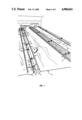
- FIG. 1 is a perspective view depicting a bowling alley fitted out a bumpering system constructed in accordance with the principles of the invention
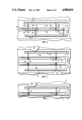
- FIG. 2 is a plan view illustrating a pair of bumpers mounted in partially nesting relationship on a relative narrow median separating two adjacent alleys;
- FIG. 3 is a view illustrating a pair of bumpers mounted in side-by-side relationship on a wider median separating two adjacent alleys and illustrating a bowling ball in contact with the bumpering surface of one of the bumpers;
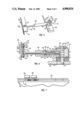
- FIG. 4 is a plan view illustrating a single bumper lying alongside an alley as it is impacted by a bowling ball;
- FIG. 5 is a perspective view of a typical mounting swivel mounted near the end of one of the bumpers;
- FIG. 6 is a sectional view depicting the preferred internal construction of one of the swivel arms of FIGS. 1-5;
- FIG. 7 is an elevation view of the assembly of FIG. 2.
- FIG. 1 depicts a bowling alley fitted out a bumpering system constructed in accordance with the principles of the invention.
- a portion of a conventional multi-alley bowling emporium 10 having alleys 11, 12 and 13.
- Alley 13 is seen to be an outside alley; that is, an alley having only one adjacent alley (i.e., alley 12); whereas alley 12 has two adjacent alleys, i.e., alleys 11 and 13.
- a pair of gutters such as gutters 14 and 15 between which there is positioned a longitudinal median or guide surface such as guide member 16 which marks the outer peripheries 17 and 18 of the gutters.
- this median or guide member is of sufficient width so as to provide needed separation between gutters and is surfaced with a horizontal cap such as cap 19 which may be constructed of any suitable material such as a wooden plank.
- a cap ordinarily extends essentiallythe entire length of the gutters (as shown) and consequently marks essentially the entire length of the alley.
- FIG. 1 reveals the presence of a conventional bowling ball 22 in progress down alley 12 and in contact with bumpering member 23 which is shown in the extended (active) position so as to guard gutter 15 and prevent balls from falling therein.
- a bumpering member 24 is shown to be in its extended position on the opposite side of alley 12 so as to guard its gutter 25 correspondingly.
- the bumpers are mounted by projecting supports such as supports 26-33 which preferably are metallic rods, although other similar supports may readily be employed in practicing the principles of the invention.
- the supports e.g. members 26-33
- swivels such as swivels 34-41 which provide connection to and support by the aforementioned guide member 16.
- an intermediate mounting member 42 is provided for ease of assembly so that all of the swivels 34-41 may be attached thereto so as to provide an assembly that is convenient to mount on an alley guide member such as member 16.
- the intermediate mounting member 42 could be eliminated or modified, and the swivels 34-41 either mounted directly to the guide member or to independent, separate mounting members, one for each swivel but shorter in length than the single guide member shown in the Figures.
- FIG. 2 is a plan view illustrating a pair of bumpers mounted in partially nesting relationship on a relative narrow guide member (median) separating two adjacent alleys. This median corresponds to median guide member 16 of FIG. 1 and therefore is identified with the symbols 16a.
- Deployment of the bumpers between their active and inactive positions may be readily accomplished by a manual swiveling movement of the bumpers or by motive power such as is illustrated by the conventional motor/gear box assemblies 44a and 45a depicted in FIG. 2.
- These assemblies although shown separately, may be combined into a single assembly in accordance with principles well known to those skilled in the art. However, by using separate assemblies (as shown), provision is made for the individual deployment of the bumper associated with each gutter.
- each alley can be individually conditioned separately for bumper ball operation or normal alley function. Since medians ordinarily separate two different alleys from each other, it will be evident that if a single actuator is employed to deploy adjacent bumpers, one half of each such adjacent alleys will be conditioned for bumper ball operation. Accordingly, it normally is undesirable to actuate adjacent bumpers from a common source. If it is desired to utilize a common actuator to condition an alley for bumper operation, an extending arm, chain or other similar member could be attached to the actuator and positioned or extended beneath the alley surface (or high overhead so as not to interfere with other alley operations), and the other bumper for the alley could be connected thereto and actuated thereby.
- FIG. 2 there are depicted the median guide member 16a gutters 14a and 15a, bumpers 23a and 43a, support arms 28a, 29a, 32a and 33a, and swivels 37a and 41a. Also shown are activating motor/gear box assemblies 44a and 45a.
- the bumpering members 23a and 43a are shown in their extended (activated) positions where they are positioned sufficiently distant from median guide member 16a so as to prevent bowling balls from entering gutters 14a or 15a.
- supports 28a, 29a, 32a and 33a (and the remaining supports) need not extend outwardly the full dimension of the gutter but only sufficiently so as to cause a bowling ball to impact the bumper (e.g., bumper 23a, 43a) before the lower surface of the ball in contact with the alley surface can contact part of the gutter.
- the bumpers may be extended to less or more than the inner edges of the gutters.
- the retracted (inactive) position of the bumpers is depicted by dashed lines which are designed by identifying symbols that include suffix letters "b".
- the retracted position of bumper 23a is shown by the dashed lines 23b
- the retracted position of bumper 43a is shown by dashed lines 43b.
- the retracted position of support arm 28a is shown by dashed lines 28b
- the retracted position of support arm 32a is shown by dashed lines 32b.
- Motor/gear box assemblies are well known in the art, and any of a number of commercially available types are suited for use in motorizing the bumper assemblies hereof. Examples of suitable motor/gear box assemblies are those manufactured by General Electric Company, Westinghouse Electric and the Grainger Company. These motor/gear box assemblies may be activated by conventional controls such as push buttons or switches that may be positioned at any convenient location such as at the motor/gearbox assembly or at a common control point.
- FIG. 3 is similar to that of FIG. 2 except that manual rather than motor action is depicted, that each bumper has its own separate supporting base, and that the median guide member is sufficiently wide so as to accommodate such separation.
- a pair of adjacent gutters 50 and 51 which are separated by a median guide member 52 on top of which are affixed two intermediate mounting members 53 and 54.
- These intermediate mounting members 53 and 54 serve as supports for swivels 55-58 in a manner similar to that described with respect to FIGS. 1 and 2.
- Shown in extended position are bumpers 59 and 60 which, when in retracted condition take the positions 59a and 60a represented by the corresponding dashed lines.
- FIG. 4 illustrates details of a single bumper lying alongside an alley as it is impacted by a bowling ball.
- a group of alleys e.g., alley 13 of FIG. 1
- the gutter 70 bounded by alley surface 71 and median guide member 72.
- an intermediate mounting member 73 which serves as a support for swivels 74 and 75.
- these swivels 74 and 75 may be operated manually or by actuator.
- FIG. 5 illustrates the preferred embodiment of the supports and swivels employed in practicing the inventive concepts hereof.
- a swivel assembly 110 which is mounted on supporting base 105.
- Such swivel assembly is shown in greater detail in FIG. 6.
- support arm 100 which may be rod shaped (as shown) or any other suitable geometry as will be evident to those skilled in the art.
- Connecting arm 100 to swivel assembly 110 is collar housing position 106 which also is described in greater detail with respect to FIG. 6.
- Connecting arm 100 is fastened to bumper 103 by fastening assembly 107 which also is shown in detail in FIG. 6.
- extending support arm 100 lies in a lower plane than that of the lower surface 101 of horizontal part 102 of bumper 103. Accordingly, when in its retracted position, lower surface 101 lies at a higher position than the top surface of swivel assembly 110 and clears it sufficiently so as to permit effective retraction.
- suitable clearance could be provided for in other ways. For example, such clearance could be provided by an offset in the axis of arm 100, the swivel could be shortened or recessed within member 105 and a fan shaped slot cut in part of member 102, or in a number of other ways that will be evident to those skilled in the art.
- Swivel assembly 110 is seen to comprise central bolt-like member 120 having theaded shaft 122 teminating in end 123.
- collar 124 Mounted on threaded shaft 122 is collar 124 and conventional nut 125.
- bearing assembly 121 which comprises conventional ball bearings 111 disposed between collar 124 and bearing race 112.
- spacing washers such as those depicted at 113-115. These washers 113-115 provide for adjustment of the vertical position of arm 100 with respect to member 105.
- Arm 100 may be fastened to collar 124 through collar portion 106 by means of conventional threads on the exterior of inner part 108 thereof which mate with female threads within a conventional recess 109 in collar 124.
- a shock absorbing assembly within extending support arm 100 collar portion 106 there is preferably provided a shock absorbing assembly, although the shock of impact of bowling balls on the bumpers may be absorbed merely by providing cushioning material 116 on the surfaces thereof. If other alternative means of providing shock absorption are provided, the arm 100 may be continuous and omit the absorbing assembly as included within collar 106. However, in the preferred embodiment, a spring-loaded piston-like mechanism is provided (as shown in FIG. 6) to provide smooth cushioning of bowling ball impact and to extend the useful life of both ball and bumper.
- collar housing 106 there is provided within collar housing 106 a cylindrical recess 130 bounded at one end 131 by a spring stop plug 132 and at the remaining end 133 by the inner end 134 of collar 135 which, in turn, is mounted on extending support arm 100 as shown.
- Communicating from the exterior to the interior of cylindrical recess 130 is longitudinal slot 136 which has opposing ends 137 and 138 which provide limits to the movement of vertical stop member 139. Since stop member 139 is affixed to collar 135, provision is made to contain the limits of travel of collar 135 (and hence the extending portion of support arm 100) within collar housing 106.
- Fastening assembly 107 comprises connecting swivel assembly 140 which is seen to interconnect the horizontal part 102 of bumper assembly 103 with support arm 100.
- Connecting swivel assembly 140 comprises body 144 to which arm 100 is fastened by any suitable means known in the art such as by screwing the threaded end 145 into a female threaded recess 146.
- aperture 147 Extending vertically through body 144 is aperture 147 which may be have a smooth interior so as to provide one part of a sleeve-type bearing for co-acting with the exterior surface of rod-like shaft 148 so that shaft 148 may rotate (swivel) therein.
- Shaft 148 preferably is threaded at both ends so that it can be retained within body 144 by bottom nut 149, top nut 150 and jam nut 151.
- either a slight clearance between the top surface of body 144 and the bottom surface of nut 150 and/or a slight clearance between the top surface of jam nut 151 and the lower surface 101 of horizontal part 102 of bumper 103 may provide the needed clearance so that arm 100 can swivel with respect to bumper 103.
- fastening nut 152 At the upper end of assembly 107 is seen fastening nut 152 which prevents bumper 103 from becoming disengaged from swivel assembly 140.
- the ends of arm 100 may be affixed to their respective connecting members 124 and 144 by any suitable means such as threaded connections. However, other means of attachment may readily be employed such a shrink fitting.
- FIG. 7 is an elevation view of the assembly of FIG. 2; and as will be observed, it depicts the preferred mode of powering the activation and deactivation of the bumpers.
- the two above-described conventional motor drive pinion gear assemblies 44a and 45a which are connected to swivel assemblies 37a and 41a and cause them to swivel upon application of energizing power to the motors.
- the motor drive pinion gear assemblies are mounted sufficiently above the upper surface of median guide member 16a so as to provide necessary clearance for retracting the bumpers.
- Any suitable control device such as a push button, switch or computer (not shown) may be employed to energize and de-energize the motors and, of course, conventional limit switches are preferably included so as to prevent overdrive.
Landscapes
- Fittings On The Vehicle Exterior For Carrying Loads, And Devices For Holding Or Mounting Articles (AREA)
Abstract
Description
Claims (20)
Priority Applications (1)
| Application Number | Priority Date | Filing Date | Title |
|---|---|---|---|
| US07/313,710 US4900024A (en) | 1989-02-22 | 1989-02-22 | Bowling alley bumper system |
Applications Claiming Priority (1)
| Application Number | Priority Date | Filing Date | Title |
|---|---|---|---|
| US07/313,710 US4900024A (en) | 1989-02-22 | 1989-02-22 | Bowling alley bumper system |
Publications (1)
| Publication Number | Publication Date |
|---|---|
| US4900024A true US4900024A (en) | 1990-02-13 |
Family
ID=23216814
Family Applications (1)
| Application Number | Title | Priority Date | Filing Date |
|---|---|---|---|
| US07/313,710 Expired - Lifetime US4900024A (en) | 1989-02-22 | 1989-02-22 | Bowling alley bumper system |
Country Status (1)
| Country | Link |
|---|---|
| US (1) | US4900024A (en) |
Cited By (21)
| Publication number | Priority date | Publication date | Assignee | Title |
|---|---|---|---|---|
| US5154418A (en) * | 1991-03-28 | 1992-10-13 | Alex Wortman | Deflecting cushion for bowling alley |
| US5181716A (en) * | 1992-03-03 | 1993-01-26 | Amf Bowling, Inc. | Bowling alley bumper system |
| WO1993004746A1 (en) * | 1991-09-12 | 1993-03-18 | Amf Bowling, Inc. | Bowling alley bumper system |
| US5207422A (en) * | 1992-02-25 | 1993-05-04 | Beene Bobby R | Bowling alley bumper system |
| US5297998A (en) * | 1992-06-11 | 1994-03-29 | Greiner Brian D | Bumpering device for bowling lanes |
| US5322476A (en) * | 1992-06-23 | 1994-06-21 | Alex Wortman | Bowling alley recessed rail deflector |
| US5358448A (en) * | 1993-07-13 | 1994-10-25 | Amf Bowling, Inc. | Bumper bowling game and erratically rollable weighted bowling ball |
| US5380251A (en) * | 1994-04-06 | 1995-01-10 | Heddon; Will | Bowling alley bumper system and method |
| US5415591A (en) * | 1994-09-20 | 1995-05-16 | Beene; Bobby R. | Arcuate gutter displacement for bumper bowling |
| US5417616A (en) * | 1994-07-07 | 1995-05-23 | Amf Bowling, Inc. | Spring biased bumper bowling system |
| US5577971A (en) * | 1992-07-31 | 1996-11-26 | File; Jonathan P. | Method of playing a combination game of bowling and random number matching |
| US5582549A (en) * | 1995-06-26 | 1996-12-10 | File; Jon P. | Method of playing a bowling game |
| US5584766A (en) * | 1992-07-31 | 1996-12-17 | File; Jon P. | Method of playing a bumper bowling system |
| US5681224A (en) * | 1996-12-12 | 1997-10-28 | Asahi Engineering & Trading Co., Ltd. | Automatic bumper system for bowling |
| US5800274A (en) * | 1996-09-20 | 1998-09-01 | Amf Bowling, Inc. | Bowling alley bumper system for producing visual effects |
| US5857918A (en) * | 1997-07-30 | 1999-01-12 | Amf Bowling, Inc. | Bumper system for a bowling alley |
| US6402629B1 (en) | 2000-06-20 | 2002-06-11 | Will Heddon | Retractable bowling alley bumper system |
| US20050221904A1 (en) * | 2004-04-01 | 2005-10-06 | Ford Gary J | Flooring system for bowling alley |
| EP1767254A4 (en) * | 2004-05-26 | 2007-12-26 | Bld Oriental Ltd | Bowling game apparatus |
| US20080227558A1 (en) * | 2007-03-12 | 2008-09-18 | Brunswick Bowling & Billilards Corporation | Bowling bumper system with lowered leading edge |
| US20170282052A1 (en) * | 2014-08-07 | 2017-10-05 | Tod S. Lyter | Bowling pin setting systems and methods wtih reconfigurable pinsetting array |
Citations (5)
| Publication number | Priority date | Publication date | Assignee | Title |
|---|---|---|---|---|
| US2628103A (en) * | 1950-07-08 | 1953-02-10 | Baciel E Parmer | Attachment for shuffleboard game boards |
| US3046012A (en) * | 1959-07-01 | 1962-07-24 | David H Marx | Bowling alley |
| US3401933A (en) * | 1965-02-23 | 1968-09-17 | Brunswick Corp | Carom bowling game |
| US4330122A (en) * | 1979-12-26 | 1982-05-18 | Zena Sheinberg | Convertible bowling alley |
| US4420155A (en) * | 1979-12-26 | 1983-12-13 | Zena Sheinberg | Convertible bowling alley |
-
1989
- 1989-02-22 US US07/313,710 patent/US4900024A/en not_active Expired - Lifetime
Patent Citations (6)
| Publication number | Priority date | Publication date | Assignee | Title |
|---|---|---|---|---|
| US2628103A (en) * | 1950-07-08 | 1953-02-10 | Baciel E Parmer | Attachment for shuffleboard game boards |
| US3046012A (en) * | 1959-07-01 | 1962-07-24 | David H Marx | Bowling alley |
| US3401933A (en) * | 1965-02-23 | 1968-09-17 | Brunswick Corp | Carom bowling game |
| US4330122A (en) * | 1979-12-26 | 1982-05-18 | Zena Sheinberg | Convertible bowling alley |
| US4420155A (en) * | 1979-12-26 | 1983-12-13 | Zena Sheinberg | Convertible bowling alley |
| US4330122B1 (en) * | 1979-12-26 | 1988-03-29 |
Non-Patent Citations (2)
| Title |
|---|
| AMF "New Products on Parade" believed to be an exerpt from Magic Triangle News published by AMF Co., Bowling Products Group, Aug. 1965, p. 13 (copy enclosed). |
| AMF New Products on Parade believed to be an exerpt from Magic Triangle News published by AMF Co., Bowling Products Group, Aug. 1965, p. 13 (copy enclosed). * |
Cited By (32)
| Publication number | Priority date | Publication date | Assignee | Title |
|---|---|---|---|---|
| US5154418A (en) * | 1991-03-28 | 1992-10-13 | Alex Wortman | Deflecting cushion for bowling alley |
| US5405295A (en) * | 1991-09-12 | 1995-04-11 | Amf Bowling, Inc. | Bowling alley bumper system |
| WO1993004746A1 (en) * | 1991-09-12 | 1993-03-18 | Amf Bowling, Inc. | Bowling alley bumper system |
| AU655320B2 (en) * | 1991-09-12 | 1994-12-15 | Amf Bowling, Inc | Bowling alley bumper system |
| US5207422A (en) * | 1992-02-25 | 1993-05-04 | Beene Bobby R | Bowling alley bumper system |
| WO1993016774A1 (en) * | 1992-02-25 | 1993-09-02 | Beene Bobby R | Improved bowling alley bumper system |
| WO1993017763A1 (en) * | 1992-03-03 | 1993-09-16 | Amf Bowling, Inc. | Bowling alley bumper system |
| USRE35232E (en) * | 1992-03-03 | 1996-05-07 | Amf Bowling, Inc. | Bowling alley bumper system |
| US5181716A (en) * | 1992-03-03 | 1993-01-26 | Amf Bowling, Inc. | Bowling alley bumper system |
| US5297998A (en) * | 1992-06-11 | 1994-03-29 | Greiner Brian D | Bumpering device for bowling lanes |
| US5322476A (en) * | 1992-06-23 | 1994-06-21 | Alex Wortman | Bowling alley recessed rail deflector |
| US5584766A (en) * | 1992-07-31 | 1996-12-17 | File; Jon P. | Method of playing a bumper bowling system |
| US5577971A (en) * | 1992-07-31 | 1996-11-26 | File; Jonathan P. | Method of playing a combination game of bowling and random number matching |
| US5358448A (en) * | 1993-07-13 | 1994-10-25 | Amf Bowling, Inc. | Bumper bowling game and erratically rollable weighted bowling ball |
| US5380251A (en) * | 1994-04-06 | 1995-01-10 | Heddon; Will | Bowling alley bumper system and method |
| US5417616A (en) * | 1994-07-07 | 1995-05-23 | Amf Bowling, Inc. | Spring biased bumper bowling system |
| AU700922B2 (en) * | 1994-09-20 | 1999-01-14 | Bobby R. Beene | Arcuate gutter displacement for bumper bowling |
| US5415591A (en) * | 1994-09-20 | 1995-05-16 | Beene; Bobby R. | Arcuate gutter displacement for bumper bowling |
| WO1996009097A1 (en) | 1994-09-20 | 1996-03-28 | Beene Bobby R | Arcuate gutter displacement for bumper bowling |
| US5582549A (en) * | 1995-06-26 | 1996-12-10 | File; Jon P. | Method of playing a bowling game |
| US5800274A (en) * | 1996-09-20 | 1998-09-01 | Amf Bowling, Inc. | Bowling alley bumper system for producing visual effects |
| US5681224A (en) * | 1996-12-12 | 1997-10-28 | Asahi Engineering & Trading Co., Ltd. | Automatic bumper system for bowling |
| US5857918A (en) * | 1997-07-30 | 1999-01-12 | Amf Bowling, Inc. | Bumper system for a bowling alley |
| US6402629B1 (en) | 2000-06-20 | 2002-06-11 | Will Heddon | Retractable bowling alley bumper system |
| US20050221904A1 (en) * | 2004-04-01 | 2005-10-06 | Ford Gary J | Flooring system for bowling alley |
| US8734263B2 (en) | 2004-04-01 | 2014-05-27 | Qubicaamf Worldwide Llc | Flooring system for bowling alley |
| EP1767254A4 (en) * | 2004-05-26 | 2007-12-26 | Bld Oriental Ltd | Bowling game apparatus |
| US20090264213A1 (en) * | 2004-05-26 | 2009-10-22 | Bld Oriental, Ltd. | Bowling game apparatus |
| US7677986B2 (en) * | 2004-05-26 | 2010-03-16 | Bld Oriental, Ltd. | Shifting guides for gutter ball prevention on a bowling alley |
| US20080227558A1 (en) * | 2007-03-12 | 2008-09-18 | Brunswick Bowling & Billilards Corporation | Bowling bumper system with lowered leading edge |
| US7575521B2 (en) | 2007-03-12 | 2009-08-18 | Brunswick Bowling & Billiards Corporation | Bowling bumper system with lowered leading edge |
| US20170282052A1 (en) * | 2014-08-07 | 2017-10-05 | Tod S. Lyter | Bowling pin setting systems and methods wtih reconfigurable pinsetting array |
Similar Documents
| Publication | Publication Date | Title |
|---|---|---|
| US4900024A (en) | Bowling alley bumper system | |
| US5238287A (en) | Front mount telescopic arm truck cover system | |
| US3762742A (en) | Electrically positioned step for vehicles | |
| ES2528445T3 (en) | Foot guard for an elevator car | |
| ES2043300T3 (en) | AUTONOMOUS LOADING AND UNLOADING DEVICE, INTEGRATED IN AN AIRCRAFT. | |
| EP0663874A1 (en) | Front mount telescopic arm truck cover system | |
| JPH04303308A (en) | Modular freight driving device for conveyor | |
| CA2299065A1 (en) | Retractable running board | |
| PT87339A (en) | BOLT OF RECIRCULATING BALLS BY DEFLECTOR OF SEMIESFERIC SUPPORTS WITH CORRUGATED-SPHERIDAL MOVEMENT FOR THE SELF-ALIGNMENT OF THE NUT OF THE NUT-DEFLECTOR ASSEMBLY | |
| ES2056863T3 (en) | SET OF CONVEYOR TRACK FOR EXTENSIBLE AND RETRACTABLE AGUILON MACHINES. | |
| US5454136A (en) | Forced air vehicle dryer and proximity control system therefor | |
| US5719553A (en) | Sealed electrical actuator assembly for hinged vehicle safety devices | |
| US6139056A (en) | Mechanical jack for automotive vehicles | |
| AU655320B2 (en) | Bowling alley bumper system | |
| US7070510B2 (en) | Bowling alley bumper system | |
| US5380251A (en) | Bowling alley bumper system and method | |
| JPS61192444A (en) | Cabin for machining-center | |
| US5243503A (en) | Fog-light assembly | |
| US5297998A (en) | Bumpering device for bowling lanes | |
| ES2091742T3 (en) | CONSOLE FOR MOUNTING SYSTEM OF ROLLING POSTS AND THE LIKE. | |
| US4989812A (en) | Body with deployable support means | |
| US20050037852A1 (en) | Bowling alley bumper system | |
| US4245715A (en) | Automatic drive prevention | |
| DE4202381A1 (en) | Motion-sensitive anti-theft alarm for motor vehicle - responds with microswitch closure to lengthening or lateral deflection or ground-contacting telescopic probe under floor | |
| JP2023066770A (en) | Vehicular step device |
Legal Events
| Date | Code | Title | Description |
|---|---|---|---|
| STCF | Information on status: patent grant |
Free format text: PATENTED CASE |
|
| FEPP | Fee payment procedure |
Free format text: PAYOR NUMBER ASSIGNED (ORIGINAL EVENT CODE: ASPN); ENTITY STATUS OF PATENT OWNER: LARGE ENTITY |
|
| FPAY | Fee payment |
Year of fee payment: 4 |
|
| AS | Assignment |
Owner name: AMF BOWLING, INC., VIRGINIA Free format text: ASSIGNMENT OF ASSIGNORS INTEREST;ASSIGNORS:CHANDLER, JOHN, MRS., HEIR TO JOHN CHANDLER, DECEASED;BEENE, BOBBY R.;REEL/FRAME:007428/0238 Effective date: 19950301 |
|
| AS | Assignment |
Owner name: CITICORP USA, INC., NEW YORK Free format text: SECURITY INTEREST;ASSIGNORS:AMF GROUP INC.;AMF BCO-CHINA, INC., A VA CORP.;AMF BCO-FRANCE ONE, INC., A VA CORP.;AND OTHERS;REEL/FRAME:007991/0086 Effective date: 19960501 |
|
| REMI | Maintenance fee reminder mailed | ||
| FEPP | Fee payment procedure |
Free format text: PAT HLDR NO LONGER CLAIMS SMALL ENT STAT AS INDIV INVENTOR (ORIGINAL EVENT CODE: LSM1); ENTITY STATUS OF PATENT OWNER: LARGE ENTITY |
|
| FEPP | Fee payment procedure |
Free format text: PAYER NUMBER DE-ASSIGNED (ORIGINAL EVENT CODE: RMPN); ENTITY STATUS OF PATENT OWNER: LARGE ENTITY |
|
| FPAY | Fee payment |
Year of fee payment: 8 |
|
| SULP | Surcharge for late payment | ||
| FPAY | Fee payment |
Year of fee payment: 12 |
|
| AS | Assignment |
Owner name: BANKERS TRUST COMPANY, NEW YORK Free format text: GRANT OF PATENT SECURITY INTEREST;ASSIGNOR:AMF BOWLING PRODUCTS, INC.;REEL/FRAME:012775/0126 Effective date: 20020228 |
|
| AS | Assignment |
Owner name: AMF GROUP INC., VIRGINIA Free format text: RELEASE BY SECURED PARTY;ASSIGNOR:CITICORP USA, INC.;REEL/FRAME:012762/0782 Effective date: 20020320 |
|
| AS | Assignment |
Owner name: AMF BOWLING PRODUCTS, INC., VIRGINIA Free format text: RELEASE OF SECURITY INTEREST;ASSIGNOR:DEUTSCHE BANK TRUST COMPANY AMERICAS;REEL/FRAME:015209/0222 Effective date: 20040227 Owner name: CREDIT SUISSE FIRST BOSTON, CAYMAN, NEW YORK Free format text: SECURITY INTEREST;ASSIGNOR:AMF BOWLING PRODUCTS, INC. (FORMERLY KNOWN AS AMF BOWLING, INC.);REEL/FRAME:015209/0370 Effective date: 20040227 |
|
| AS | Assignment |
Owner name: AMF BOWLING PRODUCTS, LLC, VIRGINIA Free format text: CONVERSION;ASSIGNOR:AMF BOWLING PRODUCTS, INC.;REEL/FRAME:016097/0542 Effective date: 20050606 |
|
| AS | Assignment |
Owner name: QUBICAAMF WORLDWIDE, LLC, VIRGINIA Free format text: CHANGE OF NAME;ASSIGNOR:AMF BOWLING PRODUCTS, LLC;REEL/FRAME:017325/0229 Effective date: 20050915 |
|
| AS | Assignment |
Owner name: ANTARES CAPITAL CORPORATION AS COLLATERAL AGENT, I Free format text: GRANT OF SECURITY INTEREST;ASSIGNOR:QUBICAAMF WORLDWIDE, LLC;REEL/FRAME:017125/0046 Effective date: 20051007 |
|
| AS | Assignment |
Owner name: ANTARES CAPITAL CORPORATION, ILLINOIS Free format text: RELEASE BY SECURED PARTY;ASSIGNOR:QUBICAAMF WORLDWIDE, LLC;REEL/FRAME:031703/0102 Effective date: 20131029 |