US4899827A - Oil well fire control system - Google Patents
Oil well fire control system Download PDFInfo
- Publication number
- US4899827A US4899827A US07/326,514 US32651489A US4899827A US 4899827 A US4899827 A US 4899827A US 32651489 A US32651489 A US 32651489A US 4899827 A US4899827 A US 4899827A
- Authority
- US
- United States
- Prior art keywords
- chemicals
- spool apparatus
- untreated water
- hydrocarbons
- flow
- Prior art date
- Legal status (The legal status is an assumption and is not a legal conclusion. Google has not performed a legal analysis and makes no representation as to the accuracy of the status listed.)
- Expired - Lifetime
Links
- 239000003129 oil well Substances 0.000 title abstract description 3
- 239000000126 substance Substances 0.000 claims abstract description 36
- XLYOFNOQVPJJNP-UHFFFAOYSA-N water Substances O XLYOFNOQVPJJNP-UHFFFAOYSA-N 0.000 claims abstract description 34
- 229930195733 hydrocarbon Natural products 0.000 claims abstract 8
- 150000002430 hydrocarbons Chemical class 0.000 claims abstract 8
- 238000002347 injection Methods 0.000 claims abstract 2
- 239000007924 injection Substances 0.000 claims abstract 2
- 229910000831 Steel Inorganic materials 0.000 claims description 7
- 238000005553 drilling Methods 0.000 claims description 7
- 239000010959 steel Substances 0.000 claims description 7
- 241000601170 Clematis lasiantha Species 0.000 claims 1
- 230000003213 activating effect Effects 0.000 claims 1
- 230000004913 activation Effects 0.000 claims 1
- JZUFKLXOESDKRF-UHFFFAOYSA-N Chlorothiazide Chemical compound C1=C(Cl)C(S(=O)(=O)N)=CC2=C1NCNS2(=O)=O JZUFKLXOESDKRF-UHFFFAOYSA-N 0.000 abstract description 7
- IJGRMHOSHXDMSA-UHFFFAOYSA-N Atomic nitrogen Chemical compound N#N IJGRMHOSHXDMSA-UHFFFAOYSA-N 0.000 abstract description 6
- CURLTUGMZLYLDI-UHFFFAOYSA-N Carbon dioxide Chemical compound O=C=O CURLTUGMZLYLDI-UHFFFAOYSA-N 0.000 abstract description 6
- LFVGISIMTYGQHF-UHFFFAOYSA-N ammonium dihydrogen phosphate Chemical compound [NH4+].OP(O)([O-])=O LFVGISIMTYGQHF-UHFFFAOYSA-N 0.000 abstract description 3
- 229910002092 carbon dioxide Inorganic materials 0.000 abstract description 3
- 239000001569 carbon dioxide Substances 0.000 abstract description 3
- 229910052757 nitrogen Inorganic materials 0.000 abstract description 3
- 239000012530 fluid Substances 0.000 abstract 1
- 230000008878 coupling Effects 0.000 description 16
- 238000010168 coupling process Methods 0.000 description 16
- 238000005859 coupling reaction Methods 0.000 description 16
- 210000002445 nipple Anatomy 0.000 description 3
- 238000009434 installation Methods 0.000 description 2
- XSQUKJJJFZCRTK-UHFFFAOYSA-N Urea Chemical compound NC(N)=O XSQUKJJJFZCRTK-UHFFFAOYSA-N 0.000 description 1
- 239000000654 additive Substances 0.000 description 1
- 239000004202 carbamide Substances 0.000 description 1
- 239000007795 chemical reaction product Substances 0.000 description 1
- 238000004821 distillation Methods 0.000 description 1
- 238000012986 modification Methods 0.000 description 1
- 230000004048 modification Effects 0.000 description 1
- 229910000028 potassium bicarbonate Inorganic materials 0.000 description 1
- 235000015497 potassium bicarbonate Nutrition 0.000 description 1
- 239000011736 potassium bicarbonate Substances 0.000 description 1
- TYJJADVDDVDEDZ-UHFFFAOYSA-M potassium hydrogencarbonate Chemical compound [K+].OC([O-])=O TYJJADVDDVDEDZ-UHFFFAOYSA-M 0.000 description 1
- 239000000843 powder Substances 0.000 description 1
- 238000007789 sealing Methods 0.000 description 1
Images

Classifications
-
- A—HUMAN NECESSITIES
- A62—LIFE-SAVING; FIRE-FIGHTING
- A62C—FIRE-FIGHTING
- A62C3/00—Fire prevention, containment or extinguishing specially adapted for particular objects or places
- A62C3/06—Fire prevention, containment or extinguishing specially adapted for particular objects or places of highly inflammable material, e.g. light metals, petroleum products
-
- E—FIXED CONSTRUCTIONS
- E21—EARTH OR ROCK DRILLING; MINING
- E21B—EARTH OR ROCK DRILLING; OBTAINING OIL, GAS, WATER, SOLUBLE OR MELTABLE MATERIALS OR A SLURRY OF MINERALS FROM WELLS
- E21B35/00—Methods or apparatus for preventing or extinguishing fires
Definitions
- the present invention provides a system and apparatus for delaying the ignition of fire at a well site or the extinguishing of a fire at a well site.
- Spool apparatus is positioned at the well site above well-known and well-utilized blow-out preventors and above the "Hydril" but below the mud return line.
- Spool apparatus is equipped with a plurality of check valves for receiving a plurality of conduits for transporting chemicals in a storage area to such spool apparatus.
- a source of water which may be untreated insofar as distillation or chemical additives is concerned and such source of water is utilized when and if the chemicals are dissipated.
- a novel check valve has been developed for incorporating into the present system to allow the water to be delivered after chemicals from the storage tanks have been dissipated.
- FIG. 1 is a side, elevational view of a well drilling rig showing installation of the spool apparatus and storage tanks of the present invention
- FIG. 2 is an enlarged side, elevational view of the spool apparatus shown in FIG. 1;
- FIG. 3 is top, partial sectional view of the spool apparatus shown in FIG. 2;
- FIG. 4 is an upper, perspective view of a coupling used with the flexible conduits or hoses which provide chemicals and water to the spool apparatus;
- FIG. 5 is an elevational, partial sectional view of the novel check valve utilized in the present invention.
- FIG. 6 is an elevational, sectional enlarged view of the water supply end of the check valve of FIG. 5;
- FIG. 7 is an enlarged view of the structure of the connection of the check valve shown in FIG. 5.
- FIG. 1 is a side, elevational view of a well drilling rig showing installation of the spool apparatus and storage tanks of the present invention.
- Spool apparatus 10 is connected above the "Hydril” 12 with a steel ring flange 14 on the bottom of the spool apparatus 10.
- the spool apparatus 10 is attached to the mud return line 16 below the mud return nipple 18 with a steel ring flange 20.
- the spool apparatus 10 is positioned in vertical alignment as part of the "Stack" to the Hydril 12 and the mud return line 16 so that the drill string 22 in the drill pipe casing 24 maybe accommodated.
- conduit 32 is connected to a water supply source (not shown) and conduit 34 is connected to a plurality of storage tanks such as storage tank 36, 38 and 40.
- storage tanks may be positioned on a trailer or skid 42 having support members such as vertical support 44 and vertical support 46.
- Horizontal member 48 may be connected between vertical support 44 and 46 to stabilize and contain the storage tanks.
- a control head 50 is positioned above tank 36 and when control head 50 is manually actuated or activated through means such as an electrical impulse in line 52 allows chemicals stored in storage tanks 36, 38 and 40 to be fed through line 34 to the spool apparatus of the present invention.
- conduit 32 provides a source of water which may be utilized when the chemicals in storage tanks 36, 38 and 40 have been dissipated.
- the drilling rig utilized in practicing the present invention includes a frame 60 positioned on a floor 62.
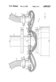
- FIG. 2 is an enlarged side, elevational view of the spool apparatus shown in FIG. 1.
- Mud return line 16 has spool apparatus 10 positioned below flange 64 which is adjacent and connected to steel ring flange 20 of spool apparatus 10.
- Steel ring flange 14 of spool apparatus 10 is adjacent and connected to flange 66 on Hydril 12.
- Spool apparatus 10 includes a plurality of check valves such as check valve 26. There are four check valves utilized in the embodiment of the invention shown and described. Check valve 26 is connected through line 68 which goes to connector 70 on coupling 28 which is connected to conduit 32. A suitable union 72 connects coupling 28 and conduit 32.
- line 74 from check valve 26 goes to connector 76 on coupling 78 which is connected to conduit 34 with union 80.
- Other lines similar to line 68 and line 74 are partially visable in FIG. 2 but, for simplicity reasons, the operation of check valve 26 only will be explained in connection with FIG. 2.
- conduit 34 provides chemicals for delaying ignition of a fire or for the extinguishing of a fire which may have started.
- a source of water is provided through conduit 32 to actuate check valve 26 so that water is provided instead of chemicals to extinguish the fire at the well site.
- the other three check valves and their associated lines act to allow water to be used to extinguish the fire at the well site after the chemicals have been dissipated.
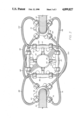
- FIG. 3 is a top, partial sectional view of the spool apparatus shown in FIG. 2.
- Conduit 32 is shown connected to union 72 which is connected to coupling 28.
- Connector 70 has line 68 connected thereto and goes to check valve 26 as explained in connection with FIG. 2.
- Line 82 is connected to connector 84 and to check valve 86.
- Line 88 is connected from check valve 86 to connector 90 on coupling 78 which is connected to conduit 34 as explained previously.
- the actuation of check valve 86 to provide water after the chemicals have been dissipated is the same as explained in connection with check valve 26.
- line 74 connects check valve 26 to coupling 78 through connector 76.
- Check valve 92 is connected through line 96 to coupling 78 and through line 98 to coupling 28.
- Check valve 100 is connected through line 102 to coupling 28 and through line 104 to coupling 78.
- Check valve 26 has a cylindrial member 106 welded with weld 108 and weld 110 to member 112 of spool apparatus 10.
- Steel ring flange 14 is shown with a plurality of openings such as opening 114 to allow connection of the spool apparatus 10 to the Hydril as explained previously.
- Operation of the check valves 26, 86, 92, and 100 is an important feature of the present invention because such operation allows water to pass through openings such as bore 116 in cylindrical member 106 after chemicals have been used but have been dissipated. Fire may be prevented by using water but generally chemicals are more effective in extinguishing a fire at the well site.
- FIG. 4 is an upper, perspective view of a coupling used with the flexible conduits or hoses which provide chemicals and water to the spool apparatus 10.
- the coupling shown in FIG. 4 may be coupling 28, for example, and has threads 120 at the upper portion of cylindrical member 122.
- Four members 124, 126, 128 and 130 are positioned at the lower portion of cylindrical member 122 and are equidistant from each other at an arcuate angle of 90° from each other.
- FIG. 5 is an elevational, partial sectional view of the novel check valve utilized in the present invention and may be, for example, check valve 26 which has been explained in use previously.
- Check valve 26 includes a cylindrical member 132 having threads 134 and 136 at each end.
- a connector 138 having threads 140 is threadedly connected to cylindrical member 132.
- Line 74 is connected to connector 138 with nipple 142.
- Nipple 142 has an O-ring 144.
- Orifice 146 includes a seat 148 having a ball 150 which may be steel.
- Ball 150 is held or positioned on seat 148 with a spring 152 having one end positioned on ball 150 and the other end positioned on shoulder 154 of bushing 155 having an O-ring 157 within connector 156.
- Connector 156 joins line 68 to cylindrical member 132 having spring 152 positioned in bore 158 and in bore 159 of bushing 155.
- Bore 158 is in communication with bore 116 of cylindrical member 106 which is connected to cylindrical member 132 with weld 108 and to member 112 with weld 110.
- Plug 162 having O-rings 164 and 166 is positioned on shoulder 168 of the large diameter portion 170 of bore 116.
- bore 116 provides chemicals from line 74 upon actuation of the control head 50 shown in FIG. 1.
- the pressurized chemicals in line 74 cause ball 150 to move from seat 148 by compressing or contracting spring 152 and ball 150 is positioned on seat 161 to block the passage of water from line 68.
- spring 152 causes ball 150 to move into seat 148 and water from line 68 goes through bore 158 and bore 116.
- the check valve shown in FIG. 1 allows pressurized chemicals to pass from line 74 through bore 158 and bore 116 and ruptures the plug 162.
- water from line 68 passes through bore 158 and bore 116.
- FIG. 6 is an elevational, sectional enlarged view of the water supply end of the check valve of FIG. 5.
- Spring 152 is positioned on shoulder 154 of bushing 155 having O-ring 157 and O-ring 172 on line 68 within connector 156 having threads 134.
- water in line 68 passes through bore 159 when ball 150 is not positioned on seat 161.
- Plug 162 prevents water from passing through bore 116 until the system is activated and chemicals pass from line 74 through bore 116 while water is shut off when ball 150 is positioned on seat 161.
- FIG. 7 is an enlarged view of the structure of the connection of the check valve shown in FIG. 5.
- Cylindrical member 106 is joined to member 112 with weld 110.
- Large diameter portion 170 of bore 116 has plug 162 positioned on shoulder 168.
- O-rings 164 and 166 provide sealing of plug 162 within bore 116 until pressure from line 74 blows-out or ruptures plug 162 as explained previously.
- the present invention provides an improvement over the system shown in my prior '506 patent by allowing inexpensive water to be used along with chemicals in delaying ignition of a fire or in the extinguishing of a fire at a well site thereby improving safety, minimizing possible loss of equipment, and also minimizing permanent damage to equipment at the well site including the drilling rig.
Landscapes
- Engineering & Computer Science (AREA)
- Life Sciences & Earth Sciences (AREA)
- Mining & Mineral Resources (AREA)
- Geology (AREA)
- Emergency Management (AREA)
- Environmental & Geological Engineering (AREA)
- Public Health (AREA)
- Business, Economics & Management (AREA)
- Chemical & Material Sciences (AREA)
- Physics & Mathematics (AREA)
- Oil, Petroleum & Natural Gas (AREA)
- Health & Medical Sciences (AREA)
- Fluid Mechanics (AREA)
- General Chemical & Material Sciences (AREA)
- Chemical Kinetics & Catalysis (AREA)
- General Life Sciences & Earth Sciences (AREA)
- Geochemistry & Mineralogy (AREA)
- Safety Valves (AREA)
Abstract
Description
Claims (1)
Priority Applications (2)
| Application Number | Priority Date | Filing Date | Title |
|---|---|---|---|
| US07/326,514 US4899827A (en) | 1988-08-01 | 1989-03-21 | Oil well fire control system |
| PCT/US1990/000766 WO1990011430A1 (en) | 1989-03-21 | 1990-02-09 | Oil well fire control system |
Applications Claiming Priority (2)
| Application Number | Priority Date | Filing Date | Title |
|---|---|---|---|
| US22681888A | 1988-08-01 | 1988-08-01 | |
| US07/326,514 US4899827A (en) | 1988-08-01 | 1989-03-21 | Oil well fire control system |
Related Parent Applications (1)
| Application Number | Title | Priority Date | Filing Date |
|---|---|---|---|
| US22681888A Continuation-In-Part | 1988-08-01 | 1988-08-01 |
Publications (1)
| Publication Number | Publication Date |
|---|---|
| US4899827A true US4899827A (en) | 1990-02-13 |
Family
ID=23272538
Family Applications (1)
| Application Number | Title | Priority Date | Filing Date |
|---|---|---|---|
| US07/326,514 Expired - Lifetime US4899827A (en) | 1988-08-01 | 1989-03-21 | Oil well fire control system |
Country Status (2)
| Country | Link |
|---|---|
| US (1) | US4899827A (en) |
| WO (1) | WO1990011430A1 (en) |
Cited By (15)
| Publication number | Priority date | Publication date | Assignee | Title |
|---|---|---|---|---|
| US5146995A (en) * | 1991-05-06 | 1992-09-15 | Hilton & Chris Enterprises | Oil well fire extinguisher having upper and lower external flame retardant-dispersing rings |
| US5156212A (en) * | 1991-05-21 | 1992-10-20 | Bryant Thomas B | Method and system for controlling high pressure flow, such as in containment of oil and gas well fires |
| FR2676499A1 (en) * | 1991-05-17 | 1992-11-20 | Djet Sarl | Method and device for extinguishing a vertical column of burning products |
| US5437332A (en) * | 1991-04-10 | 1995-08-01 | Pfeffer; John L. | Control system for wild oil and gas wells and other uncontrolled dangerous discharges |
| WO1998028517A1 (en) * | 1996-12-23 | 1998-07-02 | Paul Robert Sprehe | Well drilling system with closed circulation of gas drilling fluid and fire suppression apparatus |
| US5829528A (en) * | 1997-03-31 | 1998-11-03 | Enhanced Energy, Inc. | Ignition suppression system for down hole antennas |
| US5992544A (en) * | 1996-12-23 | 1999-11-30 | Sprehe; Paul Robert | Fire suppression apparatus for well drilling system |
| WO2000052293A3 (en) * | 1999-03-03 | 2001-01-18 | Fmc Corp | Explosion prevention system for internal turret mooring system |
| GB2390020A (en) * | 2002-06-27 | 2003-12-31 | Alec Melvin | Extinguishing oil and gas well blow-out fires |
| US20040050095A1 (en) * | 2002-08-08 | 2004-03-18 | Brigham William D. | Nitrogen generator |
| US20100012334A1 (en) * | 2005-01-17 | 2010-01-21 | Amrona Ag | Inertization Method for Preventing Fires |
| US8746357B2 (en) | 2006-10-20 | 2014-06-10 | Ada Technologies, Inc. | Fine water mist multiple orientation discharge fire extinguisher |
| US9540907B1 (en) | 2013-08-28 | 2017-01-10 | Jaco du Plessis | In-line fire control system for a hydrocarbon fluid stream |
| CN109538154A (en) * | 2018-12-19 | 2019-03-29 | 中国石油集团川庆钻探工程有限公司 | Well control equipment for nitrogen drilling of high-pressure reservoir |
| CN109577902A (en) * | 2018-12-19 | 2019-04-05 | 中国石油集团川庆钻探工程有限公司 | Well control method for nitrogen drilling of high-pressure reservoir |
Families Citing this family (3)
| Publication number | Priority date | Publication date | Assignee | Title |
|---|---|---|---|---|
| RU2143544C1 (en) * | 1998-02-16 | 1999-12-27 | Федеральный центр двойных технологий "Союз" | Method, device and system for suppressing gushers on flame in gas, oil, and gas-oil wells |
| RU2366802C2 (en) * | 2007-07-09 | 2009-09-10 | Ринат Юсупович Шафеев | Facility for fire prvention |
| RU2770220C1 (en) * | 2021-08-12 | 2022-04-14 | Федеральное государственное автономное образовательное учреждение высшего образования "Сибирский федеральный университет" | Method for extinguishing well fire with gas extinguishing agent and device for its implementation |
Citations (6)
| Publication number | Priority date | Publication date | Assignee | Title |
|---|---|---|---|---|
| US730085A (en) * | 1902-04-14 | 1903-06-02 | Anton Julius Gustav Edward Berg | Cylinder relief-valve. |
| US1958155A (en) * | 1932-01-15 | 1934-05-08 | Skelly Oil Co | Automatic multiple valve unit |
| US2138988A (en) * | 1937-09-14 | 1938-12-06 | Phillips Petroleum Co | Automatic change-over device |
| US3763936A (en) * | 1970-03-03 | 1973-10-09 | Petroles Co Franc Des | Method and apparatus for injecting fire extinguishing liquids into a fuel-carrying pipe |
| US4316506A (en) * | 1979-11-01 | 1982-02-23 | Lizzy Emergency Systems, Inc. | Oil well blow-out safety system |
| US4337831A (en) * | 1980-03-07 | 1982-07-06 | Thaxton Darrel G | Fire extinguishing apparatus for oil wells |
Family Cites Families (1)
| Publication number | Priority date | Publication date | Assignee | Title |
|---|---|---|---|---|
| US2371293A (en) * | 1945-03-13 | Hydraulic valve |
-
1989
- 1989-03-21 US US07/326,514 patent/US4899827A/en not_active Expired - Lifetime
-
1990
- 1990-02-09 WO PCT/US1990/000766 patent/WO1990011430A1/en not_active Ceased
Patent Citations (6)
| Publication number | Priority date | Publication date | Assignee | Title |
|---|---|---|---|---|
| US730085A (en) * | 1902-04-14 | 1903-06-02 | Anton Julius Gustav Edward Berg | Cylinder relief-valve. |
| US1958155A (en) * | 1932-01-15 | 1934-05-08 | Skelly Oil Co | Automatic multiple valve unit |
| US2138988A (en) * | 1937-09-14 | 1938-12-06 | Phillips Petroleum Co | Automatic change-over device |
| US3763936A (en) * | 1970-03-03 | 1973-10-09 | Petroles Co Franc Des | Method and apparatus for injecting fire extinguishing liquids into a fuel-carrying pipe |
| US4316506A (en) * | 1979-11-01 | 1982-02-23 | Lizzy Emergency Systems, Inc. | Oil well blow-out safety system |
| US4337831A (en) * | 1980-03-07 | 1982-07-06 | Thaxton Darrel G | Fire extinguishing apparatus for oil wells |
Cited By (22)
| Publication number | Priority date | Publication date | Assignee | Title |
|---|---|---|---|---|
| US5437332A (en) * | 1991-04-10 | 1995-08-01 | Pfeffer; John L. | Control system for wild oil and gas wells and other uncontrolled dangerous discharges |
| US5146995A (en) * | 1991-05-06 | 1992-09-15 | Hilton & Chris Enterprises | Oil well fire extinguisher having upper and lower external flame retardant-dispersing rings |
| FR2676499A1 (en) * | 1991-05-17 | 1992-11-20 | Djet Sarl | Method and device for extinguishing a vertical column of burning products |
| US5156212A (en) * | 1991-05-21 | 1992-10-20 | Bryant Thomas B | Method and system for controlling high pressure flow, such as in containment of oil and gas well fires |
| WO1998028517A1 (en) * | 1996-12-23 | 1998-07-02 | Paul Robert Sprehe | Well drilling system with closed circulation of gas drilling fluid and fire suppression apparatus |
| US5890549A (en) * | 1996-12-23 | 1999-04-06 | Sprehe; Paul Robert | Well drilling system with closed circulation of gas drilling fluid and fire suppression apparatus |
| US5975219A (en) * | 1996-12-23 | 1999-11-02 | Sprehe; Paul Robert | Method for controlling entry of a drillstem into a wellbore to minimize surge pressure |
| US5992544A (en) * | 1996-12-23 | 1999-11-30 | Sprehe; Paul Robert | Fire suppression apparatus for well drilling system |
| US5829528A (en) * | 1997-03-31 | 1998-11-03 | Enhanced Energy, Inc. | Ignition suppression system for down hole antennas |
| WO2000052293A3 (en) * | 1999-03-03 | 2001-01-18 | Fmc Corp | Explosion prevention system for internal turret mooring system |
| US6341572B1 (en) | 1999-03-03 | 2002-01-29 | Fmc Corporation | Explosion prevention system for internal turret mooring system |
| WO2000058600A1 (en) * | 1999-03-26 | 2000-10-05 | Formation Preservation, Inc. | Fire suppression apparatus for well drilling system |
| GB2390020A (en) * | 2002-06-27 | 2003-12-31 | Alec Melvin | Extinguishing oil and gas well blow-out fires |
| GB2390020B (en) * | 2002-06-27 | 2005-04-13 | Alec Melvin | A high fluid velocity generation device for extinguishing oil and gas well blow-out fires |
| US20040050095A1 (en) * | 2002-08-08 | 2004-03-18 | Brigham William D. | Nitrogen generator |
| WO2004015347A3 (en) * | 2002-08-08 | 2004-09-30 | Pacific Cons Ind L P | Nitrogen generator |
| US6910350B2 (en) * | 2002-08-08 | 2005-06-28 | Pacific Consolidated Industries, Llc | Nitrogen generator |
| US20100012334A1 (en) * | 2005-01-17 | 2010-01-21 | Amrona Ag | Inertization Method for Preventing Fires |
| US8746357B2 (en) | 2006-10-20 | 2014-06-10 | Ada Technologies, Inc. | Fine water mist multiple orientation discharge fire extinguisher |
| US9540907B1 (en) | 2013-08-28 | 2017-01-10 | Jaco du Plessis | In-line fire control system for a hydrocarbon fluid stream |
| CN109538154A (en) * | 2018-12-19 | 2019-03-29 | 中国石油集团川庆钻探工程有限公司 | Well control equipment for nitrogen drilling of high-pressure reservoir |
| CN109577902A (en) * | 2018-12-19 | 2019-04-05 | 中国石油集团川庆钻探工程有限公司 | Well control method for nitrogen drilling of high-pressure reservoir |
Also Published As
| Publication number | Publication date |
|---|---|
| WO1990011430A1 (en) | 1990-10-04 |
Similar Documents
| Publication | Publication Date | Title |
|---|---|---|
| US4899827A (en) | Oil well fire control system | |
| US3782458A (en) | Upright, swivelable buoyed conduit for offshore system | |
| US11492248B2 (en) | Method and apparatus for multi-line fuel delivery | |
| US4176986A (en) | Subsea riser and flotation means therefor | |
| US4095421A (en) | Subsea energy power supply | |
| US6186239B1 (en) | Casing annulus remediation system | |
| US3354951A (en) | Marine drilling apparatus | |
| US4163477A (en) | Method and apparatus for closing underwater wells | |
| US5826610A (en) | Breakaway coupling device | |
| US7464751B1 (en) | High pressure adapter assembly for use on blow out preventers | |
| US4316506A (en) | Oil well blow-out safety system | |
| US5699822A (en) | Breakaway coupling device | |
| US8448915B2 (en) | Increased shear power for subsea BOP shear rams | |
| US9540907B1 (en) | In-line fire control system for a hydrocarbon fluid stream | |
| US20110284236A1 (en) | Negative accumulator for BOP shear rams | |
| US20110284237A1 (en) | Drilling riser release method | |
| AU2017350844B2 (en) | Relief well injection spool apparatus and method for killing a blowing well | |
| NO338633B1 (en) | Method for underbalanced wellbore and system for supplying density-reducing fluid to a subsea location | |
| US3847214A (en) | Well and pipeline construction | |
| US3463227A (en) | Fire arrester for a petroleum well | |
| US2041394A (en) | Fire extinguisher and blowout preventer | |
| NO316888B1 (en) | Security system and method for providing an additional security barrier on a wellhead | |
| EP3294981B1 (en) | Method and system for controlling gas flow | |
| US5146995A (en) | Oil well fire extinguisher having upper and lower external flame retardant-dispersing rings | |
| US20220136366A1 (en) | Hydraulic accumulator system |
Legal Events
| Date | Code | Title | Description |
|---|---|---|---|
| AS | Assignment |
Owner name: DOUG POOLE INTERESTS, TEXAS Free format text: ASSIGNMENT OF ASSIGNORS INTEREST.;ASSIGNOR:POOLE, DOUGLAS;REEL/FRAME:006251/0977 Effective date: 19920923 |
|
| REMI | Maintenance fee reminder mailed | ||
| FEPP | Fee payment procedure |
Free format text: PETITION RELATED TO MAINTENANCE FEES DENIED/DISMISSED (ORIGINAL EVENT CODE: PMFD); ENTITY STATUS OF PATENT OWNER: SMALL ENTITY Free format text: PETITION RELATED TO MAINTENANCE FEES FILED (ORIGINAL EVENT CODE: PMFP); ENTITY STATUS OF PATENT OWNER: SMALL ENTITY |
|
| FEPP | Fee payment procedure |
Free format text: PETITION RELATED TO MAINTENANCE FEES FILED (ORIGINAL EVENT CODE: PMFP); ENTITY STATUS OF PATENT OWNER: SMALL ENTITY |
|
| FEPP | Fee payment procedure |
Free format text: PETITION RELATED TO MAINTENANCE FEES GRANTED (ORIGINAL EVENT CODE: PMFG); ENTITY STATUS OF PATENT OWNER: SMALL ENTITY |
|
| REIN | Reinstatement after maintenance fee payment confirmed | ||
| FP | Lapsed due to failure to pay maintenance fee |
Effective date: 19940213 |
|
| FPAY | Fee payment |
Year of fee payment: 4 |
|
| SULP | Surcharge for late payment | ||
| STCF | Information on status: patent grant |
Free format text: PATENTED CASE |
|
| DP | Notification of acceptance of delayed payment of maintenance fee |