US4899726A - Furnace inducer outlet elbow - Google Patents
Furnace inducer outlet elbow Download PDFInfo
- Publication number
- US4899726A US4899726A US07/242,922 US24292288A US4899726A US 4899726 A US4899726 A US 4899726A US 24292288 A US24292288 A US 24292288A US 4899726 A US4899726 A US 4899726A
- Authority
- US
- United States
- Prior art keywords
- inducer
- vent pipe
- rectangular
- flow
- outlet assembly
- Prior art date
- Legal status (The legal status is an assumption and is not a legal conclusion. Google has not performed a legal analysis and makes no representation as to the accuracy of the status listed.)
- Expired - Lifetime
Links
- 239000000411 inducer Substances 0.000 title claims abstract description 86
- 239000007789 gas Substances 0.000 claims description 13
- 230000007704 transition Effects 0.000 claims description 7
- 238000009833 condensation Methods 0.000 claims description 5
- 230000005494 condensation Effects 0.000 claims description 5
- 238000000034 method Methods 0.000 claims description 3
- 238000007789 sealing Methods 0.000 claims description 2
- 239000013536 elastomeric material Substances 0.000 claims 2
- 230000015572 biosynthetic process Effects 0.000 claims 1
- 239000000463 material Substances 0.000 claims 1
- 229920001084 poly(chloroprene) Polymers 0.000 claims 1
- 239000003546 flue gas Substances 0.000 abstract description 5
- 230000000452 restraining effect Effects 0.000 abstract 1
- 239000000567 combustion gas Substances 0.000 description 5
- 238000009434 installation Methods 0.000 description 5
- 238000002485 combustion reaction Methods 0.000 description 4
- UGFAIRIUMAVXCW-UHFFFAOYSA-N Carbon monoxide Chemical compound [O+]#[C-] UGFAIRIUMAVXCW-UHFFFAOYSA-N 0.000 description 2
- 230000004888 barrier function Effects 0.000 description 1
- 238000010276 construction Methods 0.000 description 1
- 239000000446 fuel Substances 0.000 description 1
- 238000012423 maintenance Methods 0.000 description 1
- 238000004519 manufacturing process Methods 0.000 description 1
- 230000013011 mating Effects 0.000 description 1
- 238000012986 modification Methods 0.000 description 1
- 230000004048 modification Effects 0.000 description 1
- 230000008569 process Effects 0.000 description 1
- 230000008439 repair process Effects 0.000 description 1
- 238000011144 upstream manufacturing Methods 0.000 description 1
- XLYOFNOQVPJJNP-UHFFFAOYSA-N water Substances O XLYOFNOQVPJJNP-UHFFFAOYSA-N 0.000 description 1
Images
Classifications
-
- F—MECHANICAL ENGINEERING; LIGHTING; HEATING; WEAPONS; BLASTING
- F23—COMBUSTION APPARATUS; COMBUSTION PROCESSES
- F23L—SUPPLYING AIR OR NON-COMBUSTIBLE LIQUIDS OR GASES TO COMBUSTION APPARATUS IN GENERAL ; VALVES OR DAMPERS SPECIALLY ADAPTED FOR CONTROLLING AIR SUPPLY OR DRAUGHT IN COMBUSTION APPARATUS; INDUCING DRAUGHT IN COMBUSTION APPARATUS; TOPS FOR CHIMNEYS OR VENTILATING SHAFTS; TERMINALS FOR FLUES
- F23L17/00—Inducing draught; Tops for chimneys or ventilating shafts; Terminals for flues
- F23L17/005—Inducing draught; Tops for chimneys or ventilating shafts; Terminals for flues using fans
-
- F—MECHANICAL ENGINEERING; LIGHTING; HEATING; WEAPONS; BLASTING
- F24—HEATING; RANGES; VENTILATING
- F24H—FLUID HEATERS, e.g. WATER OR AIR HEATERS, HAVING HEAT-GENERATING MEANS, e.g. HEAT PUMPS, IN GENERAL
- F24H8/00—Fluid heaters characterised by means for extracting latent heat from flue gases by means of condensation
- F24H8/006—Means for removing condensate from the heater
-
- Y—GENERAL TAGGING OF NEW TECHNOLOGICAL DEVELOPMENTS; GENERAL TAGGING OF CROSS-SECTIONAL TECHNOLOGIES SPANNING OVER SEVERAL SECTIONS OF THE IPC; TECHNICAL SUBJECTS COVERED BY FORMER USPC CROSS-REFERENCE ART COLLECTIONS [XRACs] AND DIGESTS
- Y02—TECHNOLOGIES OR APPLICATIONS FOR MITIGATION OR ADAPTATION AGAINST CLIMATE CHANGE
- Y02B—CLIMATE CHANGE MITIGATION TECHNOLOGIES RELATED TO BUILDINGS, e.g. HOUSING, HOUSE APPLIANCES OR RELATED END-USER APPLICATIONS
- Y02B30/00—Energy efficient heating, ventilation or air conditioning [HVAC]
Definitions
- This invention relates generally to induced draft furnaces and, more particularly, to a transition member for interconnecting an inducer housing discharge opening to a vent pipe for a condensing furnace.
- a motor driven inducer blower is provided to enhance the mixing of combustion air with the fuel in order to better facilitate the combustion process.
- the inducer may be located upstream and be of the blow-through type, it is more common to place it downstream of the combustion process so as to draw the supply air into the burner and cause the combustion gases to flow through the heat exchangers and the vent pipe to be discharged outside.
- the discharge air to the vent pipe is normally at a sufficiently high temperature that condensation does not occur within the vent pipe.
- the temperature of the discharge gas in the vent pipe is sufficiently low that condensation is likely to occur. If such condensation runs back into the inducer, damage may occur.
- Condensing furnace vent pipes are normally installed so as to come out the side of the furnace. For ease of installation, it may be easier to place the vent pipe through the top of the furnace; however, it is preferred that the top of the furnace be relatively unobscured by such piping to leave space for the filters or air cleaner assembly. Since the particular furnace installation requirements will vary with respect to the desirability for left or right side discharge, provision is normally made for installation in either direction by the serviceman in the field. This is commonly accomplished by the use of some type of transition device such as an inducer outlet box or assembly which is used to turn the flow of the discharge air from its upward path exiting the inducer housing, to a substantially horizontal flow to the vent pipe in either the left or right side.
- transition device such as an inducer outlet box or assembly which is used to turn the flow of the discharge air from its upward path exiting the inducer housing, to a substantially horizontal flow to the vent pipe in either the left or right side.
- Another object of the present invention is the provision for an inducer outlet assembly which prevents the flow of condensate from the vent pipe to the inducer housing.
- Yet another object of the present invention is the provision for an inducer outlet assembly which offers a minimum restriction to the flow of exhaust gases therethrough.
- Still another object of the present invention is the provision for an inducer outlet assembly which can be attached to a rectangular inducer discharge opening without attendant leakage.
- Another object of the present invention is the provision for securing a rectangular inducer outlet assembly to a rectangular inducer discharge opening in such a manner that leakage does not occur therebetween.
- Yet another object of the present invention is the provision for an inducer outlet assembly which is easy to assemble and disassemble.
- Still another object of the present invention is the provision for an inducer outlet assembly which is easy to manufacture and effective in use.
- an inducer outlet assembly for attachment between a furnace flue gas draft inducer outlet and a vent pipe, is provided with a well portion near the end which attaches to the vent pipe.
- the well portion includes a bottom wall with a condensate drainage opening therein, and an adjoining vertical wall which rises to a vertical height which is substantially higher than the attached vent pipe lower wall such that any condensate that tends to flow down the vent pipe toward the inducer will tend to be restricted by the vertical wall and be collected by the well so it can be drained off by the condensate drainage opening.
- the inducer outlet assembly is provided with a smooth rounded corner from the top of said well vertical wall to a vertical section of the inducer outlet assembly which connects to the inducer housing.
- the rounded corner provides for minimal flow restriction as the exhaust gases turn the corner in their flow from the inducer housing to the vent pipe.
- an air tight connection is made between a rectangular overlapping portion of the flexible inducer outlet assembly and an overlapped rectangular portion of the inducer housing by forming a crown intermediate each of the inducer assembly rectangular sides.
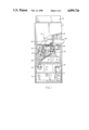
- FIG. 1 is a partially broken away front elevational view of a furnace in accordance with the present invention.
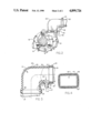
- FIG. 2 is an enlarged view of the inducer and inducer outlet elbow portion thereof.
- FIG. 3 is a longitudinal sectional view of the inducer outlet elbow portion thereof.
- FIG. 4 is a sectional view of the installed inducer outlet elbow as seen along lines 4--4 in FIG. 2.
- the invention is shown generally at 10 as applied to a downflow furnace 11 wherein the circulating air flows downwardly over the heat exchanger(s) and the combustion gases flow upwardly through the heat exchanger(s) (not shown).
- the air cleaner assembly 12 is shown at the top of the furnace.
- a burner assembly 13 has a manifold 14 leading to a plurality of spaced burners into which gas is supplied by way of a gas valve 16.
- the combustion gases rise from the burners and flow through a primary heat exchanger (not shown) to an intermediate chamber 17.
- the combustion gases then flow through a condensing heat exchanger (not shown), where further heat is removed therefrom, and then to a draft inducer 18.
- the inducer 18, which is driven by a motor 19, operates in a conventional manner to draw air into the combustion burners and through the primary and condensing heat exchangers, and finally to the inducer housing assembly 21 where it is discharged by way of an inducer housing discharge elbow 22 to a vent pipe 23.
- the condensate is allowed to enter the inducer housing assembly 21, damage may occur to the inducer. Accordingly, it is necessary to capture and dispose of the condensate before it reaches the inducer housing assembly. This is accomplished in accordance with the present invention by providing appropriate structure within the discharge elbow 22 for collection and disposal of the condensate.
- the condensate is first collected in a structure to be described hereinafter, and then it is drained by way of a vent drain tube 24 and condensate drain tube 26 to a condensate trap assembly 27 from which it is then drained to an appropriate location such as to the outside.
- the inducer housing discharge elbow 22 with its condensate collection structure and the related devices for interconnecting it between the inducer housing assembly 21 and the vent pipe 23, is shown in greater detail.
- the elbow 22 can be oriented in either direction to thereby accommodate the individual installation requirements. That is, although it is shown installed in such a position as to discharge from the right side of the furnace as shown in FIG. 1, it may just as well be turned 180° such that it accommodates a vent pipe emerging from the left side of the furnace.
- the elbow 22 is shown to include a large radius side 28 and a small radius side 29, with both having smooth curving surfaces to permit the relatively unrestricted flow of exhaust gases through the channel 31 formed therebetween.
- the small radius side 29 of the elbow 22 is comprised of the integrally connected straight upwardly extending section 32, a curved section 33, and a straight horizontally extending section 34.
- a well structure 36 which is defined on two sides by side and bottom walls 37 and 38, respectively. The well 36 functions to prevent the flow of condensate into the inducer housing assembly 21 in a manner to be described hereinafter.
- a condensate discharge drain 39 Depending from the well bottom wall 38 is a condensate discharge drain 39 with its associated opening 41.
- the vent drain tube 24 is connected to the condensate discharge drain 39 as shown in FIG. 1.
- a suitable clamp 44 such as a hose clamp or the like, is secured in the depression 43 as shown in FIGS. 2 and 3.
- the inner diameter of the vent pipe 23 is only slightly above the well bottom wall 38, with the well side wall 37 extending vertically thereabove a substantial distance.
- the flue gas discharge opening 46 in the inducer housing assembly 21 is defined by a rectangular structure 47.
- a rectangular structure is more easily formed than would be a round structure at the discharge end of the inducer housing assembly 21.
- an outlet box assembly as set forth in U.S. Pat. No. 4,603,680 mentioned hereinabove, a rectangular discharge opening is easily adaptable to such an assembly.
- the clamp 49 tended to maintain a tight, leak-proof seal at the corners of the inlet lip 48 but not at the spaces therebetween, especially near the midpoint of the sides.
- the present invention addresses this problem by making the inlet lip of variable thickness as shown in FIG. 4.
- the inlet lip 48 is of minimum thickness at its corners and of increasing thickness toward the midpoint of its sides.
Landscapes
- Engineering & Computer Science (AREA)
- Chemical & Material Sciences (AREA)
- Combustion & Propulsion (AREA)
- Mechanical Engineering (AREA)
- General Engineering & Computer Science (AREA)
- Physics & Mathematics (AREA)
- Thermal Sciences (AREA)
- Incineration Of Waste (AREA)
Abstract
Description
Claims (14)
Priority Applications (3)
| Application Number | Priority Date | Filing Date | Title |
|---|---|---|---|
| US07/242,922 US4899726A (en) | 1988-09-12 | 1988-09-12 | Furnace inducer outlet elbow |
| CA000605811A CA1287780C (en) | 1988-09-12 | 1989-07-17 | Furnace inducer outlet elbow |
| CA000615893A CA1312348C (en) | 1988-09-12 | 1990-10-11 | Furnace inducer outlet elbow |
Applications Claiming Priority (1)
| Application Number | Priority Date | Filing Date | Title |
|---|---|---|---|
| US07/242,922 US4899726A (en) | 1988-09-12 | 1988-09-12 | Furnace inducer outlet elbow |
Publications (1)
| Publication Number | Publication Date |
|---|---|
| US4899726A true US4899726A (en) | 1990-02-13 |
Family
ID=22916654
Family Applications (1)
| Application Number | Title | Priority Date | Filing Date |
|---|---|---|---|
| US07/242,922 Expired - Lifetime US4899726A (en) | 1988-09-12 | 1988-09-12 | Furnace inducer outlet elbow |
Country Status (2)
| Country | Link |
|---|---|
| US (1) | US4899726A (en) |
| CA (1) | CA1287780C (en) |
Cited By (31)
| Publication number | Priority date | Publication date | Assignee | Title |
|---|---|---|---|---|
| US5309890A (en) * | 1993-07-30 | 1994-05-10 | Carrier Corporation | Dual-sided condensate trap for furnace |
| US5341795A (en) * | 1993-06-30 | 1994-08-30 | Carrier Corporation | Inducer for condensing furnace |
| US5368010A (en) * | 1992-07-29 | 1994-11-29 | Consolidated Industries Corp. | Multi-position forced air furnace |
| US5375586A (en) * | 1993-08-11 | 1994-12-27 | Inter-City Products Corporation (Usa) | Condensate isolator and drainage system for furnace |
| US5379749A (en) * | 1993-08-16 | 1995-01-10 | Carrier Corporation | Condensate trap for multi-poise furnace |
| US5620302A (en) * | 1995-08-31 | 1997-04-15 | Fasco Industries, Inc. | Dynamic condensate evacuator for high efficiency gas furnaces |
| US5630368A (en) * | 1993-05-24 | 1997-05-20 | The University Of Tennessee Research Corporation | Coal feed and injection system for a coal-fired firetube boiler |
| US5704343A (en) * | 1996-09-11 | 1998-01-06 | American Standard Inc. | Furnace condensate trap |
| EP0924437A3 (en) * | 1997-12-17 | 2000-02-23 | L.N. di NATALINI LINO & C. - S.r.l. | Fan casing with condensate collection and drainage |
| US6305369B1 (en) * | 2000-10-18 | 2001-10-23 | Carrier Corporation | Safeguard for furnace draft system |
| US6536378B2 (en) | 2000-01-11 | 2003-03-25 | Fasco Industries, Inc. | Apparatus for evacuating condensation from furnace pipe systems |
| US20050047922A1 (en) * | 2003-09-03 | 2005-03-03 | Brown Fred A. | Apparatus and method for maintaining an operating condition for a blower |
| US20050252213A1 (en) * | 2004-05-17 | 2005-11-17 | Brown Fred A | Condensation removal for use with a draft inducer |
| GB2415033A (en) * | 2004-06-11 | 2005-12-14 | Neil Kirby | A flue turret elbow with a channel guiding condensation to a reservoir in a collector |
| US20060065211A1 (en) * | 2004-09-01 | 2006-03-30 | Aos Holding Company | Blower and method of conveying fluids |
| US20060185620A1 (en) * | 2002-09-09 | 2006-08-24 | Brown Fred A | Condensation removal for use with a draft inducer |
| US20070052230A1 (en) * | 2005-08-24 | 2007-03-08 | Rcf Technologies, Inc. | Duct sealing apparatus |
| US20070236010A1 (en) * | 2006-04-06 | 2007-10-11 | Campau Daniel N | Connector for corrugated conduit |
| US20090193822A1 (en) * | 2004-07-02 | 2009-08-06 | Aqualizer, Llc | Moisture condensation control system |
| US20130129491A1 (en) * | 2011-04-19 | 2013-05-23 | Zhongshan Broad-Ocean Motor Manufacturing Co., Ltd. | Water drainage system for blower |
| US20140339809A1 (en) * | 2013-05-20 | 2014-11-20 | Ford Global Technologies, Llc | Hose and system for hose clamp registration |
| US9038622B2 (en) | 2010-10-15 | 2015-05-26 | Carrier Corporation | Condensate collector system for multi-poise gas furnace system |
| US9074791B2 (en) | 2010-10-15 | 2015-07-07 | Carrier Corporation | Gas furnace condensate collector box |
| WO2017218096A1 (en) * | 2016-06-15 | 2017-12-21 | Regal Beloit America, Inc. | Water heater blower assembly having a low exhaust port |
| US10488077B2 (en) | 2015-06-15 | 2019-11-26 | Carrier Corporation | Furnace inducer elbow, gas furnace system having elbow, and method of manufacturing elbow |
| US10746414B2 (en) | 2017-04-28 | 2020-08-18 | Trane International Inc. | Flue vent adapter for multi-poise furnace |
| US11015836B2 (en) | 2016-06-15 | 2021-05-25 | Regal Beloit America, Inc. | Water heater blower assembly having a low exhaust port |
| US20220082111A1 (en) * | 2019-09-02 | 2022-03-17 | Zhongshan Broad-Ocean Motor Co., Ltd. | Adapter for induced draft fan and induced draft fan comprising the same |
| US11306944B2 (en) | 2016-06-15 | 2022-04-19 | Regal Beloit America, Inc. | Water heater blower assembly having a low exhaust port |
| US20220196284A1 (en) * | 2020-12-22 | 2022-06-23 | Noritz Corporation | Combustion device and water heating device |
| US11473857B2 (en) * | 2020-01-04 | 2022-10-18 | Intellihot, Inc. | Modular exhaust |
Citations (8)
| Publication number | Priority date | Publication date | Assignee | Title |
|---|---|---|---|---|
| US2171023A (en) * | 1938-12-19 | 1939-08-29 | Buxton Jay | Rubber faucet extension |
| US2824575A (en) * | 1954-07-12 | 1958-02-25 | Milprint Inc | Air conditioner attachment |
| US4059293A (en) * | 1975-12-01 | 1977-11-22 | Sipler Clarence L | Connector |
| US4380348A (en) * | 1981-02-18 | 1983-04-19 | Clamp-All Corp. | Pipe clamping assembly |
| US4583770A (en) * | 1982-11-04 | 1986-04-22 | Oy Wiik & Hoglund Ab | Pipe joint seal |
| US4603680A (en) * | 1984-12-10 | 1986-08-05 | Carrier Corporation | Furnace inducer outlet box assembly |
| US4653466A (en) * | 1983-01-06 | 1987-03-31 | Amana Refrigeration, Inc. | Apparatus and method for removing recuperative condensate |
| US4763695A (en) * | 1986-06-20 | 1988-08-16 | Buckhorn Rubber Products, Inc. | Coupling hose assembly |
-
1988
- 1988-09-12 US US07/242,922 patent/US4899726A/en not_active Expired - Lifetime
-
1989
- 1989-07-17 CA CA000605811A patent/CA1287780C/en not_active Expired - Lifetime
Patent Citations (8)
| Publication number | Priority date | Publication date | Assignee | Title |
|---|---|---|---|---|
| US2171023A (en) * | 1938-12-19 | 1939-08-29 | Buxton Jay | Rubber faucet extension |
| US2824575A (en) * | 1954-07-12 | 1958-02-25 | Milprint Inc | Air conditioner attachment |
| US4059293A (en) * | 1975-12-01 | 1977-11-22 | Sipler Clarence L | Connector |
| US4380348A (en) * | 1981-02-18 | 1983-04-19 | Clamp-All Corp. | Pipe clamping assembly |
| US4583770A (en) * | 1982-11-04 | 1986-04-22 | Oy Wiik & Hoglund Ab | Pipe joint seal |
| US4653466A (en) * | 1983-01-06 | 1987-03-31 | Amana Refrigeration, Inc. | Apparatus and method for removing recuperative condensate |
| US4603680A (en) * | 1984-12-10 | 1986-08-05 | Carrier Corporation | Furnace inducer outlet box assembly |
| US4763695A (en) * | 1986-06-20 | 1988-08-16 | Buckhorn Rubber Products, Inc. | Coupling hose assembly |
Cited By (44)
| Publication number | Priority date | Publication date | Assignee | Title |
|---|---|---|---|---|
| US5368010A (en) * | 1992-07-29 | 1994-11-29 | Consolidated Industries Corp. | Multi-position forced air furnace |
| US5630368A (en) * | 1993-05-24 | 1997-05-20 | The University Of Tennessee Research Corporation | Coal feed and injection system for a coal-fired firetube boiler |
| US5341795A (en) * | 1993-06-30 | 1994-08-30 | Carrier Corporation | Inducer for condensing furnace |
| US5309890A (en) * | 1993-07-30 | 1994-05-10 | Carrier Corporation | Dual-sided condensate trap for furnace |
| US5375586A (en) * | 1993-08-11 | 1994-12-27 | Inter-City Products Corporation (Usa) | Condensate isolator and drainage system for furnace |
| US5379749A (en) * | 1993-08-16 | 1995-01-10 | Carrier Corporation | Condensate trap for multi-poise furnace |
| US5620302A (en) * | 1995-08-31 | 1997-04-15 | Fasco Industries, Inc. | Dynamic condensate evacuator for high efficiency gas furnaces |
| US5704343A (en) * | 1996-09-11 | 1998-01-06 | American Standard Inc. | Furnace condensate trap |
| EP0924437A3 (en) * | 1997-12-17 | 2000-02-23 | L.N. di NATALINI LINO & C. - S.r.l. | Fan casing with condensate collection and drainage |
| US6536378B2 (en) | 2000-01-11 | 2003-03-25 | Fasco Industries, Inc. | Apparatus for evacuating condensation from furnace pipe systems |
| US6305369B1 (en) * | 2000-10-18 | 2001-10-23 | Carrier Corporation | Safeguard for furnace draft system |
| US6595201B2 (en) * | 2000-10-18 | 2003-07-22 | Carrier Corporation | Safeguard for furnace draft system |
| US7363882B2 (en) | 2002-09-09 | 2008-04-29 | Comair Rotron, Inc. | Condensation removal for use with a draft inducer |
| US20060185620A1 (en) * | 2002-09-09 | 2006-08-24 | Brown Fred A | Condensation removal for use with a draft inducer |
| US20050047922A1 (en) * | 2003-09-03 | 2005-03-03 | Brown Fred A. | Apparatus and method for maintaining an operating condition for a blower |
| US20050252213A1 (en) * | 2004-05-17 | 2005-11-17 | Brown Fred A | Condensation removal for use with a draft inducer |
| GB2415033A (en) * | 2004-06-11 | 2005-12-14 | Neil Kirby | A flue turret elbow with a channel guiding condensation to a reservoir in a collector |
| US20090193822A1 (en) * | 2004-07-02 | 2009-08-06 | Aqualizer, Llc | Moisture condensation control system |
| US8028438B2 (en) * | 2004-07-02 | 2011-10-04 | Aqualizer, Llc | Moisture condensation control system |
| US7354244B2 (en) | 2004-09-01 | 2008-04-08 | Aos Holding Company | Blower and method of conveying fluids |
| US20060065211A1 (en) * | 2004-09-01 | 2006-03-30 | Aos Holding Company | Blower and method of conveying fluids |
| US20070052230A1 (en) * | 2005-08-24 | 2007-03-08 | Rcf Technologies, Inc. | Duct sealing apparatus |
| US7452005B2 (en) * | 2005-08-24 | 2008-11-18 | Rcf Technologies, Inc. | Duct sealing apparatus |
| US20070236010A1 (en) * | 2006-04-06 | 2007-10-11 | Campau Daniel N | Connector for corrugated conduit |
| US9074791B2 (en) | 2010-10-15 | 2015-07-07 | Carrier Corporation | Gas furnace condensate collector box |
| US9038622B2 (en) | 2010-10-15 | 2015-05-26 | Carrier Corporation | Condensate collector system for multi-poise gas furnace system |
| US20130129491A1 (en) * | 2011-04-19 | 2013-05-23 | Zhongshan Broad-Ocean Motor Manufacturing Co., Ltd. | Water drainage system for blower |
| US20140339809A1 (en) * | 2013-05-20 | 2014-11-20 | Ford Global Technologies, Llc | Hose and system for hose clamp registration |
| US9683691B2 (en) * | 2013-05-20 | 2017-06-20 | Ford Global Technologies, Llc | Hose and system for hose clamp registration |
| US10578236B2 (en) | 2013-05-20 | 2020-03-03 | Ford Global Technologies, Llc | Hose and system for hose clamp registration |
| US10488077B2 (en) | 2015-06-15 | 2019-11-26 | Carrier Corporation | Furnace inducer elbow, gas furnace system having elbow, and method of manufacturing elbow |
| GB2567077A (en) * | 2016-06-15 | 2019-04-03 | Regal Beloit America Inc | Water heater blower assembly having a low exhaust port |
| US10443891B2 (en) | 2016-06-15 | 2019-10-15 | Regal Beloit America, Inc. | Water heater blower assembly having a low exhaust port |
| WO2017218096A1 (en) * | 2016-06-15 | 2017-12-21 | Regal Beloit America, Inc. | Water heater blower assembly having a low exhaust port |
| GB2567077B (en) * | 2016-06-15 | 2020-09-16 | Regal Beloit America Inc | Water heater blower assembly having a low exhaust port |
| US11015836B2 (en) | 2016-06-15 | 2021-05-25 | Regal Beloit America, Inc. | Water heater blower assembly having a low exhaust port |
| US11215379B2 (en) | 2016-06-15 | 2022-01-04 | Regal Beloit America, Inc. | Water heater blower assembly having a low exhaust port |
| US11306944B2 (en) | 2016-06-15 | 2022-04-19 | Regal Beloit America, Inc. | Water heater blower assembly having a low exhaust port |
| US11971196B2 (en) | 2016-06-15 | 2024-04-30 | Regal Beloit America, Inc. | Water heater blower assembly having a low exhaust port |
| US10746414B2 (en) | 2017-04-28 | 2020-08-18 | Trane International Inc. | Flue vent adapter for multi-poise furnace |
| US20220082111A1 (en) * | 2019-09-02 | 2022-03-17 | Zhongshan Broad-Ocean Motor Co., Ltd. | Adapter for induced draft fan and induced draft fan comprising the same |
| US11788554B2 (en) * | 2019-09-02 | 2023-10-17 | Zhongshan Broad-Ocean Motor Co., Ltd. | Adapter for induced draft fan and induced draft fan comprising the same |
| US11473857B2 (en) * | 2020-01-04 | 2022-10-18 | Intellihot, Inc. | Modular exhaust |
| US20220196284A1 (en) * | 2020-12-22 | 2022-06-23 | Noritz Corporation | Combustion device and water heating device |
Also Published As
| Publication number | Publication date |
|---|---|
| CA1287780C (en) | 1991-08-20 |
Similar Documents
| Publication | Publication Date | Title |
|---|---|---|
| US4899726A (en) | Furnace inducer outlet elbow | |
| US4481935A (en) | Flue pipe connection | |
| US5375586A (en) | Condensate isolator and drainage system for furnace | |
| US4603680A (en) | Furnace inducer outlet box assembly | |
| US10145581B2 (en) | Condensate pan with condensate trap | |
| US5775318A (en) | Forced air condensing furnace and heat exchanger manifold therefor | |
| US5400853A (en) | Modular heating/cooling coil design and coil flow connector | |
| US5379751A (en) | Inducer collector box seal for induction condenser furnace | |
| US5313930A (en) | Air intake for furnace | |
| US6053162A (en) | Balanced flue sealed vent terminal assembly | |
| US5582159A (en) | Condensate handlers for multi-poise furnace | |
| CA2077126A1 (en) | High Efficiency Induced Draft Condensing Furnace with Horizontal Plastic Vent Termination Assembly | |
| EP0056670A2 (en) | Assembly comprising a heat recovery device | |
| US4892045A (en) | Condensate drain system | |
| CA1312348C (en) | Furnace inducer outlet elbow | |
| US11473857B2 (en) | Modular exhaust | |
| CN218993687U (en) | Condensing gas water heater | |
| US20080072892A1 (en) | Catch for condensates | |
| CN216114653U (en) | Heating and hot water supply device | |
| CN115523504B (en) | Blocking covers, exhaust pipes, exhaust systems and gas water heaters | |
| MXPA06010145A (en) | Looped system fuel-fired fluid heating/storage device. | |
| EP0762054A1 (en) | Pressure ring for roof duct | |
| CA1235970A (en) | Flue pipe connection | |
| CN215372087U (en) | Can collect organic waste gas of hydrops and collect conveying system | |
| CN209326081U (en) | A kind of gas heater of modified flue and its composition |
Legal Events
| Date | Code | Title | Description |
|---|---|---|---|
| AS | Assignment |
Owner name: CARRIER CORPORATION, CARRIER PARKWAY, SYRACUSE, NY Free format text: ASSIGNMENT OF ASSIGNORS INTEREST.;ASSIGNOR:WATERMAN, TIMOTHY J.;REEL/FRAME:004969/0515 Effective date: 19880901 Owner name: CARRIER CORPORATION, NEW YORK Free format text: ASSIGNMENT OF ASSIGNORS INTEREST;ASSIGNOR:WATERMAN, TIMOTHY J.;REEL/FRAME:004969/0515 Effective date: 19880901 |
|
| STCF | Information on status: patent grant |
Free format text: PATENTED CASE |
|
| AS | Assignment |
Owner name: CARRIER CORPORATION, A DE CORP., NEW YORK Free format text: ASSIGNOR HERBY CONFIRMS THE ENTIRE INTEREST IN SAID INVENTION TO ASSIGNEE IN AS ASSIGNMENT EXECUTED ON SEPTEMBER 1, 1988;ASSIGNOR:WATERMAN, TIMOTHY J.;REEL/FRAME:005562/0982 Effective date: 19901210 |
|
| FEPP | Fee payment procedure |
Free format text: PAYOR NUMBER ASSIGNED (ORIGINAL EVENT CODE: ASPN); ENTITY STATUS OF PATENT OWNER: LARGE ENTITY |
|
| FPAY | Fee payment |
Year of fee payment: 4 |
|
| FPAY | Fee payment |
Year of fee payment: 8 |
|
| FPAY | Fee payment |
Year of fee payment: 12 |