US4899628A - Dynamically compensating counterbalance - Google Patents
Dynamically compensating counterbalance Download PDFInfo
- Publication number
- US4899628A US4899628A US07/205,688 US20568888A US4899628A US 4899628 A US4899628 A US 4899628A US 20568888 A US20568888 A US 20568888A US 4899628 A US4899628 A US 4899628A
- Authority
- US
- United States
- Prior art keywords
- slide
- counterweight
- housing
- cylinder
- compensating
- Prior art date
- Legal status (The legal status is an assumption and is not a legal conclusion. Google has not performed a legal analysis and makes no representation as to the accuracy of the status listed.)
- Expired - Fee Related
Links
- 239000012530 fluid Substances 0.000 claims abstract description 76
- 238000005520 cutting process Methods 0.000 claims abstract description 15
- 239000000463 material Substances 0.000 claims abstract description 10
- 238000006073 displacement reaction Methods 0.000 claims abstract description 7
- 230000004044 response Effects 0.000 claims description 13
- 238000003754 machining Methods 0.000 claims description 8
- 229910000831 Steel Inorganic materials 0.000 claims description 5
- 239000010959 steel Substances 0.000 claims description 5
- 230000000717 retained effect Effects 0.000 claims description 4
- 230000013011 mating Effects 0.000 claims description 2
- 241000632072 Rallus tenuirostris Species 0.000 claims 1
- 230000000875 corresponding effect Effects 0.000 description 9
- 230000007246 mechanism Effects 0.000 description 7
- 125000006850 spacer group Chemical group 0.000 description 5
- 230000008901 benefit Effects 0.000 description 4
- 238000010276 construction Methods 0.000 description 4
- 230000008859 change Effects 0.000 description 3
- 238000005461 lubrication Methods 0.000 description 3
- 244000309464 bull Species 0.000 description 2
- 239000003638 chemical reducing agent Substances 0.000 description 2
- 238000012986 modification Methods 0.000 description 2
- 230000004048 modification Effects 0.000 description 2
- 229920006364 Rulon (plastic) Polymers 0.000 description 1
- GYDJEQRTZSCIOI-UHFFFAOYSA-N Tranexamic acid Chemical compound NCC1CCC(C(O)=O)CC1 GYDJEQRTZSCIOI-UHFFFAOYSA-N 0.000 description 1
- 229910001080 W alloy Inorganic materials 0.000 description 1
- MEOSMFUUJVIIKB-UHFFFAOYSA-N [W].[C] Chemical compound [W].[C] MEOSMFUUJVIIKB-UHFFFAOYSA-N 0.000 description 1
- 230000001154 acute effect Effects 0.000 description 1
- 239000003831 antifriction material Substances 0.000 description 1
- 238000011109 contamination Methods 0.000 description 1
- 230000008878 coupling Effects 0.000 description 1
- 238000010168 coupling process Methods 0.000 description 1
- 238000005859 coupling reaction Methods 0.000 description 1
- 230000003247 decreasing effect Effects 0.000 description 1
- 230000001627 detrimental effect Effects 0.000 description 1
- 238000010586 diagram Methods 0.000 description 1
- 230000000694 effects Effects 0.000 description 1
- 239000002783 friction material Substances 0.000 description 1
- 238000004519 manufacturing process Methods 0.000 description 1
- 239000000843 powder Substances 0.000 description 1
- 230000036316 preload Effects 0.000 description 1
Images

Classifications
-
- B—PERFORMING OPERATIONS; TRANSPORTING
- B23—MACHINE TOOLS; METAL-WORKING NOT OTHERWISE PROVIDED FOR
- B23B—TURNING; BORING
- B23B29/00—Holders for non-rotary cutting tools; Boring bars or boring heads; Accessories for tool holders
- B23B29/03—Boring heads
- B23B29/034—Boring heads with tools moving radially, e.g. for making chamfers or undercuttings
- B23B29/03432—Boring heads with tools moving radially, e.g. for making chamfers or undercuttings radially adjustable during manufacturing
- B23B29/03467—Boring heads with tools moving radially, e.g. for making chamfers or undercuttings radially adjustable during manufacturing by means of gears and racks
-
- B—PERFORMING OPERATIONS; TRANSPORTING
- B23—MACHINE TOOLS; METAL-WORKING NOT OTHERWISE PROVIDED FOR
- B23Q—DETAILS, COMPONENTS, OR ACCESSORIES FOR MACHINE TOOLS, e.g. ARRANGEMENTS FOR COPYING OR CONTROLLING; MACHINE TOOLS IN GENERAL CHARACTERISED BY THE CONSTRUCTION OF PARTICULAR DETAILS OR COMPONENTS; COMBINATIONS OR ASSOCIATIONS OF METAL-WORKING MACHINES, NOT DIRECTED TO A PARTICULAR RESULT
- B23Q1/00—Members which are comprised in the general build-up of a form of machine, particularly relatively large fixed members
- B23Q1/25—Movable or adjustable work or tool supports
- B23Q1/44—Movable or adjustable work or tool supports using particular mechanisms
- B23Q1/48—Movable or adjustable work or tool supports using particular mechanisms with sliding pairs and rotating pairs
- B23Q1/4804—Movable or adjustable work or tool supports using particular mechanisms with sliding pairs and rotating pairs a single rotating pair followed perpendicularly by a single sliding pair
-
- B—PERFORMING OPERATIONS; TRANSPORTING
- B23—MACHINE TOOLS; METAL-WORKING NOT OTHERWISE PROVIDED FOR
- B23Q—DETAILS, COMPONENTS, OR ACCESSORIES FOR MACHINE TOOLS, e.g. ARRANGEMENTS FOR COPYING OR CONTROLLING; MACHINE TOOLS IN GENERAL CHARACTERISED BY THE CONSTRUCTION OF PARTICULAR DETAILS OR COMPONENTS; COMBINATIONS OR ASSOCIATIONS OF METAL-WORKING MACHINES, NOT DIRECTED TO A PARTICULAR RESULT
- B23Q11/00—Accessories fitted to machine tools for keeping tools or parts of the machine in good working condition or for cooling work; Safety devices specially combined with or arranged in, or specially adapted for use in connection with, machine tools
- B23Q11/0032—Arrangements for preventing or isolating vibrations in parts of the machine
- B23Q11/0035—Arrangements for preventing or isolating vibrations in parts of the machine by adding or adjusting a mass, e.g. counterweights
-
- G—PHYSICS
- G01—MEASURING; TESTING
- G01M—TESTING STATIC OR DYNAMIC BALANCE OF MACHINES OR STRUCTURES; TESTING OF STRUCTURES OR APPARATUS, NOT OTHERWISE PROVIDED FOR
- G01M1/00—Testing static or dynamic balance of machines or structures
- G01M1/30—Compensating imbalance
- G01M1/36—Compensating imbalance by adjusting position of masses built-in the body to be tested
-
- Y—GENERAL TAGGING OF NEW TECHNOLOGICAL DEVELOPMENTS; GENERAL TAGGING OF CROSS-SECTIONAL TECHNOLOGIES SPANNING OVER SEVERAL SECTIONS OF THE IPC; TECHNICAL SUBJECTS COVERED BY FORMER USPC CROSS-REFERENCE ART COLLECTIONS [XRACs] AND DIGESTS
- Y10—TECHNICAL SUBJECTS COVERED BY FORMER USPC
- Y10T—TECHNICAL SUBJECTS COVERED BY FORMER US CLASSIFICATION
- Y10T82/00—Turning
- Y10T82/12—Radially moving rotating tool inside bore
- Y10T82/125—Tool simultaneously moving axially
-
- Y—GENERAL TAGGING OF NEW TECHNOLOGICAL DEVELOPMENTS; GENERAL TAGGING OF CROSS-SECTIONAL TECHNOLOGIES SPANNING OVER SEVERAL SECTIONS OF THE IPC; TECHNICAL SUBJECTS COVERED BY FORMER USPC CROSS-REFERENCE ART COLLECTIONS [XRACs] AND DIGESTS
- Y10—TECHNICAL SUBJECTS COVERED BY FORMER USPC
- Y10T—TECHNICAL SUBJECTS COVERED BY FORMER US CLASSIFICATION
- Y10T82/00—Turning
- Y10T82/25—Lathe
- Y10T82/2529—Revolvable cutter heads
Definitions
- This invention pertains to balancing devices, and more particularly to apparatus for balancing rotating bodies having variable mass centers.
- the challenges of designing and building equipment capable of efficiently and accurately producing round parts extends to machine tools wherein a contouring head machines a stationary workpiece.
- An exemplary contouring machine is the NumeriboreTM machine manufactured by the Davis Tool Division of AMCA International Corporation.
- contouring heads Because of the high speeds demanded of modern contouring machines, the contouring heads must be accurately balanced. Unbalanced conditions result in inaccurate geometries. When cutting varying bore sizes or other tapered surfaces of revolution with contouring heads, the changing distance of the cutting tool and tool slide from the axis of rotation requires the application of a correspondingly changing counterbalance force.
- the balancing problem is aggravated when contouring is performed by relatively small heads.
- the small envelope required for the contouring head to machine specific workpieces makes it very difficult to provide sufficient mass to properly counterbalance the cutting tool and slide.
- the problem is especially acute in contouring heads having relatively large slide travels and high rotational speeds.
- U.S. Pat. No. 4,577,535 describes a contouring machine tool having a counterbalanced contouring head. A pair of counterweights are geared inside the contouring head to move radially to the axis of rotation in the opposite direction as the cutting tool and slide. While generally satisfactory, the system of the U.S. Pat. No. 4,577,535 has a maximum operating speed that is somewhat lower than desired.
- U.S. Pat. No. 4,620,464 discloses a counterbalanced boring head, but the tool travel available is very limited. Other known counterbalance systems are also unable to satisfactorily compensate for variations in the positions of the radially moveable parts and variations in the weights of the radially movable parts of high speed contouring heads.
- a dynamically compensating counterbalance is provided that is operable over wide variations of speeds, center of mass eccentricities, and masses of the eccentric parts. This is accomplished by apparatus that includes fluid actuated counterweights and a servo controlled tuning system.
- the dynamically compensating counterbalance may be incorporated into a machine tool contouring head that is mounted for rotation about a central axis.
- Contouring head mounting may be to the rotary sleeve of a generally conventional headstock.
- the contouring head includes a housing guided in and bolted to the sleeve.
- the housing is formed with a generally T-shaped passage, through which a slide is reciprocable in directions radial to the central axis. To the slide is mounted cutting tool.
- the contouring head includes a mechanism that is driven by a spindle received within the sleeve.
- the spindle reciprocates along the central axis under the control of a conventional numerical control system.
- the drive mechanism between the spindle and the contouring head slide is preferably an anti-backlash drive, such as a wound-up gear train, as is known in the art. Reciprocation of the spindle inside the rotating sleeve produces corresponding radial motion of the slide and cutting tool for varying the diameter or profile of a workpiece being machined by the contouring head.
- the contouring head of the present invention includes a counterweight that is received within hollow regions of the contouring head slide and housing.
- the counterweight reciprocates parallel to, in the opposite direction of, and in the same general plane as the slide.
- opposite reciprocation of the counterweight in correlation with the slide is accomplished by providing the counterbalance system with at least two fluid cylinders having their respective casings secured to the contouring head housing.
- the piston rod of one of the cylinders is connected to the slide.
- the piston rod of the second cylinder is connected to the counterweight.
- the piston side of the first or slide cylinder is ported to the piston side of the second cylinder, with a fixed amount of incompressible fluid trapped between the two cylinders. There need be no fluid on the piston rod side of either cylinder.
- the counterweight and slide are designed such that their respective centers of mass are radially opposite of the central axis of rotation, as viewed longitudinally along the central axis, irrespective of their relative positions within the contouring head housing. Further, the counterweight center of mass is located between the central axis and the second or counterweight cylinder. Consequently, when the contouring head is rotated about the central axis, the counterweight exerts a centrifugal force on the fluid in the second cylinder, thereby producing pressure on the pistons in both cylinders. Because the slide is under numerical control, the pressure in the cylinders has no effect on the slide position.
- the first cylinder piston As the slide is moved radially within the housing by the numerically control spindle, the first cylinder piston is moved an equal distance.
- the fluid trapped between the two cylinders flows between their respective piston ends to cause the second cylinder piston to move a distance proportional to the slide and first cylinder piston travel.
- the two cylinders are arranged within the housing such that the counterweight travels in the opposite direction as the slide.
- the pressure produced by the centrifugal force of the counterweight on the fluid in the second cylinder properly keeps both cylinders full of fluid when the slide is traveling in the direction away from the first cylinder.
- the slide and first cylinder piston act as a pump that slaves the second cylinder piston and counterweight to counterbalance the radially moving slide and tooling.
- the counterweight includes some components that are preferably made of a high density material. Further, the counterweight mass is preferably greater than the mass of the slide and tool holder. Accordingly, the counterweight travel need not be as great as the corresponding slide travel to properly counterbalance the slide. Scaling the relative travels of the slide and counterweight to a ratio other than unity may be accomplished by utilizing cylinders of unequal areas.
- the contouring head is compensatable in a dynamic mode to correct out-of-balance conditions without moving the slide. Slight but detrimental imbalances can arise due to variations or inaccuracies in the assumed locations or masses of the various rotating parts, such as the tooling, or in the scaling of the slide and counterweight cylinders.
- the present invention includes a third hydraulic cylinder.
- the third or dynamic compensating cylinder may be single acting, with fluid only on the piston end.
- the third cylinder piston end is located within the contouring head housing, with the fluid therein being connected in a closed system with the fluid of the first and second cylinders. Thus, a definite amount of fluid is trapped in the three cylinders and in the passages therebetween.
- the third cylinder piston rod is connected to a compensating ring that is guided on the headstock sleeve for rotation therewith.
- the compensating ring is reciprocable relative to the sleeve and contouring head housing. Reciprocation of the ring on the sleeve moves the third cylinder piston relative to the contouring head housing.
- Third cylinder piston motion varies the amount of fluid in the third cylinder piston end. The centrifugal force produced by the rotating counterweight acting on the second cylinder creates pressure on the trapped fluid. The fluid pressure assures that the third cylinder piston end is always filled with fluid as the compensating ring reciprocates the third cylinder piston. Because the slide is under numerical control, the first cylinder piston does not change position with changes in the fluid within the second and third cylinders.
- Reciprocating motion of the compensating ring may be by means of an annular threaded member fixed to the headstock.
- a collar has threads that engage those of the threaded annular member.
- the collar is fabricated with gear teeth that connect through a suitable drive train to a servo motor. Energizing the servo motor causes the collar to rotate relative to the headstock and threaded annular member, thereby causing the collar to axially move relative to the headstock.
- the compensating ring is coupled to the collar by means of a thrust bearing, such that the compensating ring moves axially with the collar.
- energizing the servo motor rotates the collar relative to the headstock, and, by means of the threads, axially displaces the collar, compensating ring, and third cylinder pistons to vary counterweight radial position without movement of the contouring head slide.
- the thrust bearing between the collar and the compensating ring permits relative rotation between those two parts under the influence of the servo motor.
- an accelerometer of known design maybe mounted to the machine tool headstock.
- the accelerometer is installed within a control circuit so as to sense unbalanced forces in at least the plane of greatest headstock compliance.
- the signals from the accelerometer are fed through a tracking filter that removes all frequencies other than that of the spindle speed.
- the filtered signal is then used to control the servo motor.
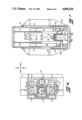
- FIG. 1 is a side view of a typical machine tool that advantageously uses the dynamically compensating counterbalance of the present invention.
- FIG. 2 is a view taken along lines 2--2 of FIG. 1.
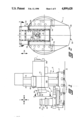
- FIG. 3 is a cross sectional view taken along lines 3--3 of FIG. 2.
- FIG. 4 is a cross sectional view taken through the central axis of rotation of the contouring head of the present invention.
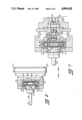
- FIG. 5 is a cross sectional view taken along lines 5--5 of FIG. 4.
- FIG. 6 is a cross sectional view taken along lines 6--6 of FIG. 4.
- FIG. 7 is a cross sectional view taken along line 7--7 of FIG. 4.
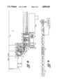
- FIG. 8 is a view, partially broken and partially in cross section, of the mechanism for providing dynamic compensation for the counterbalance system of the present invention.
- FIG. 9 is a block diagram of the control for the dynamically compensating counterbalance of the present invention.
- reference numeral 1 indicates a contouring head that includes the present invention.
- the contouring head 1 is shown mounted to the headstock 3 of a numerically controlled machine tool 5.
- the invention is not limited to machine tool applications.
- the machine tool 5 includes a bed 7 secured to a foundation 9 by means of leveling jacks 11.
- An upright column 13 is fastened to the bed 7.
- the column 13 is manufactured with vertical ways 15 for reciprocatingly guiding the headstock 3 along a Y axis.
- the column way faces define a vertical plane.
- a saddle 17 is mounted to the bed 7 for reciprocating in first horizontal directions along a W axis parallel to the plane defined by the faces of the column ways 15.
- the saddle 17 includes ways for reciprocatingly mounting and guiding a table 19.
- Table motion is in horizontal directions along an X axis perpendicular to the saddle motion.
- a workpiece 21 may be secured directly to the machine table 19. Alternately, as illustrated, the workpiece 21 may be fastened to holding fixtures 23, such as a rotary table or work changing pallet, as are known in the art.
- the workpiece is shown with a representative tapered surface of revolution 25 having a horizontal axis 27 that is to be machined by the machine tool 5.
- Surface 25 is depicted as a bore, but it will be appreciated that external surfaces of revolution are also machinable using the present invention.
- a sleeve 37 is mounted in the machine headstock 3 for rotation about a central axis 31.
- the central axis 31 defines a Z axis.
- the sleeve 37 is journaled in the headstock by means of bearings 39.
- Rotary motion to the sleeve is provided by a bull gear 41 keyed thereto.
- a suitable drive train (not shown) powered by a motor 43, FIG. 1.
- the contouring head 1 Machining of the workpiece bore 25 is accomplished by the contouring head 1, which is mounted to the headstock 3 for rotation about the central axis 31.
- the contouring head includes a cutting tool 29 that is fastened to a tool post 32.
- the tool post 32 is fixed to a slide 33.
- the slide 33 is reciprocable within a housing 35 in a plane perpendicular to the central axis. Slide reciprocation is in the directions of arrow 34 between a housing open end 36 and a closed end 38. The slide reciprocates by means of a mechanism to be described presently.
- the contouring head housing 35 is attached to the headstock sleeve 37.
- the contouring head housing 35 is formed with a pilot 45 that accurately fits within a bore in the sleeve. Screws 47 securely attach the housing to the sleeve for rotation therewith.
- a spindle 49 is axially slideable within the sleeve 37 for driving the slide through a drive train 51.
- the drive train 51 comprises a set of racks 53 secured to an interior surface 54 of the slide.
- Two sets of meshing gears 55 and 57 are interposed between the spindle 49 and the slide racks 53.
- a rack 59 is attached to a flatened spindle extension 58.
- the gear train 51 is of an anti-backlash design.
- the set of gears 55 comprises two gears 55a and 55b journaled on a common shaft 61 that is mounted in the contouring head housing 35.
- the second set of gears 57 comprises two gears 57a and 57b mounted on a common shaft 63.
- Gear 57a meshes with rack 53a of the rack set 53, which is fixed to the slide interior surface 54.
- Rack 53b is adjustable on the slide.
- a wedge 60 (FIG. 4) is interposed between one end of the rack 53b and a sloped surface 62 formed on the slide 33. The wedge 60 is held in place by screws 80.
- the wedge slides along the surface 62 and displaces the rack 53b.
- the gears 57a, 57b and 55a, 55b are rotated against the spindle rack 59 and slide rack 53a to take all backlash out of the drive train 51.
- a predetermined amount of preload can be installed in the drive train by means of the wedge.
- the contouring head 1 includes an Inductosyn scale 64 mounted to the housing and a slider 66 mounted to the slide, FIG. 5.
- the Inductosyn scale 64 and slider 66 are incorporated into the contouring machine numerical control system, as is known in the art.
- the contouring head 1 comprises several gibs, as are best shown in FIGS. 2, 5, and 6.
- Gibs 68 and 70 retain the slide against the housing in a direction parallel to the Z axis.
- Gib 72 retains the slide in a direction transverse to the Z axis against a plate 74 fastened to the housing.
- Lubrication is provided to the various mating surfaces between the slide, gibs, and plate 74 by suitable passages drilled through those components and through the housing. Lubrication is supplied to the housing via a flexible conduit 77 connected between the spindle 49 and the slide, FIG. 4.
- Conventional wipers and seals 78 minimize lubrication leakage outside the sleeve and contamination entrance into the housing, FIG. 2.
- the contouring head slide 33 is seen to have four internal cavities.
- the first cavity 65 provides space for a mechanism for rigidly but removably mounting the tool post 32 to the slide. Such mechanism does not form any part of the present invention, and therefore it will not be discussed further herein.
- Slide 33 further defines a central cavity 67 and a pair of smaller side cavities 69 and 71.
- the cavities 65, 67, 69, and 71 are open to the outer end 73 of the slide, and they are covered by a plate 75. The cavities are exposed at the slide inner end 79.
- the present invention comprises a counterbalance system 81.
- the counterbalance system 81 includes a pair of hydraulic cylinders 83 and 85 and a counterweight 87.
- a pair of hydraulic cylinders 83 and 85 may be employed.
- Both of the hydraulic cylinders 83 and 85 may be single acting with hydraulic fluid present only on their respective piston ends.
- the respective cylinder casings are joined to a common manifold 86 that in turn is fastened to the contouring head housing 35.
- the manifold 86 is manufactured with internal passages 88 that connect the piston ends of the two cylinders to each other. Consequently, a fixed quantity of fluid is trapped in the cylinder piston ends and in the manifold passages 88.
- Counterweight 87 is composed of three major pieces and several smaller components.
- the first major counterweight piece 90 has a cross section that slideingly fits within the slide central cavity 67.
- U-shaped rails 93a and 93b secured to the inside of the cavity 67 guide the counterweight piece 90 therein.
- major counterweight pieces 89 and 91 are guided by rails 95 and 97 within the housing cavities 69 and 71, respectively.
- the sliding surfaces of the three major pieces 89, 90, and 91 are preferably coated with a low friction material, such as Rulon anti-friction material.
- Reference numeral 99 represents a horseshoe bracket having a base leg 100.
- the piston rod 103 of the cylinder 85 is connected to the horseshoe bracket base leg 100.
- To the front face of horseshoe bracket 99 is fastened a top plate 102.
- a smaller bottom plate 104 is fastened to the back side of the horseshoe bracket within an appropriate cutout.
- Fasteners extending through the horseshoe bracket and front plate 102 and back plate 104 secure a pair of bottom plates 106 and 108 thereto.
- the bottom plates 106 and 108 are located in general alignment with the slide cavities 69 and 71, respectively.
- Counterweight 87 includes the bracket 99; the plates 102, 104, 106, and 108; and the spacers 107 and 110.
- the thickness of the spacers 107 and 110 can be varied to change the locations of the counterweight pieces 89 and 91. In that manner, optimum counterweight location can be obtained to accommodate such variables in changes in the tooling position on the slide 33.
- the piston rod 101 of the cylinder 83 is connected to the slide, as by a nut 114 fastened at the slide inner end 79.
- FIGS. 1-6 the contouring head slide 33 and tool post 32 are shown at the position of maximum radial travel, that is, at the farthest design distance from the central axis 31.
- the piston rod 101 of the cylinder 83 is fully extended, and the piston rod 103 of the cylinder 85 is fully retracted.
- Moving the slide toward the central axis by means of the spindle 49 pushes the piston rod 101 into the cylinder 83.
- Fluid forced from the cylinder 83 flows through the manifold passage 88 and enters the piston end of cylinder 85.
- Piston rod 103 is forced out of the cylinder 85, thereby moving the counterweight 87 toward the central axis, and the slide tends to swallow the oppositely moving counterweight. Because the counterweight 87 is located in the same general plane of rotation as the slide, problems with dynamic imbalance at high rotational speeds are minimized.
- the pressure of the fluid in the cylinders 83 and 85 and in the manifold 86 is zero psi gauge.
- the counterweight pieces 89, 90, and 91 are designed such that their respective centers of mass are located between the central axis 31 and the cylinder 85. Accordingly, when the contouring head is rotating, the counterweight 87 exerts a centrifugal force on the piston rod 103. In turn, the piston rod force creates the pressure within the hydraulic fluid.
- the pressure in the fluid assures that the fluid properly fills the cylinder 83 when the slide is fed away from the housing closed end 38 and the cylinder 83. Since the force exerted on the fluid in cylinder 85 increases as the square of the contouring head rotational speed, sufficient hydraulic pressure is always available for proper counterbalance operation.
- Counterweight travel may be proportionately scaled relative to slide travel.
- proportional scaling is accomplished by designing the cylinders 83 and 85 with proportional areas.
- the cylinder 85 has a greater piston area than cylinder 83, such that a given travel of the slide produces a lesser travel of the counterweight.
- the counterweight pieces 89, 90, and 91 are fabricated from a high density material.
- a suitable material is a carbon tungsten alloy powder that is fused into the particular shapes of the counterweight pieces. Such a material has a density approximately 2.6 times greater than that of steel.
- the front plate 102, back plate 104, side plates 106 and 108, and the spacers 107 are also made from the high density material.
- the high density counterweight pieces provide the significant advantage of occupying minimum space within the slide 33 and housing 35, and also of being able to function properly at radial positions relatively close to the central axis 31.
- the high density components and travel scaling are very important in the design of the contouring head 1, which has a small envelope but relatively large slide travel.
- the counterweight 87 protrudes a relatively great distance from the slide inner end 79.
- a pair of keys 105 are fastened to the housing 35 near the closed end 38 thereof, as is best shown in FIG. 6. Complimentary notches formed in the counterweight bottom plates 106 and 108 slide over the keys 105. Thus, guidance is provided for the counterweight portion that protrudes beyond the slide guide rails 93, 95, and 97, which are best shown in FIGS. 3 and 5.
- the dynamically compensating counterbalance is capable of adjusting the radial position of the counterweight 87 without corresponding motion of the slide 33.
- Such counterweight adjustment is important for optimum balance under certain conditions where imbalances can produce out-of-round geometries on the workpiece bore 25, FIG. 1.
- dynamic compensation is performed by apparatus that includes at least one and preferably more compensating cylinders that are ported to the cylinders 83 and 85.
- a fluid cylinder 109 is depicted that has its piston end 111 securely retained in the contouring head housing 35.
- the compensating cylinder 109 is single acting, with no fluid being present on the side of the piston rod 117. It is desirable that three compensating cylinders be employed, with the cylinders being equidistantly spaced circumferentially around the housing. However, more than three cylinders may be used if required by the specific application.
- each cylinder is ported through a seal, such as an O-ring 113, to a respective passage 115 drilled into the housing.
- a seal such as an O-ring 113
- fluid passages that are not integral with the housing may be used.
- the passages 115 of all the compensating cylinders are connected, such that the cylinders are hydraulically connected to each other.
- the interior passages of the compensating cylinders are ported internally within the housing to the passage 88 of the manifold 86. Also see FIG. 4. Consequently, the fluid trapped between the two cylinders 83 and 85 also includes the fluid trapped in the passages 115 connected to the compensating cylinders. With a trapped volume of incompressible fluid, the displacement of the piston of any one cylinder will tend to cause a corresponding displacement of the pistons of the other cylinders.
- the rods 117 thereof are connected to a compensating ring 119.
- the compensating ring 119 is generally annular in shape, and it fits over the periphery 121 of the sleeve flange 123.
- the compensating ring is formed with lobes 125 that correspond to and receive the respective cylinder piston rods.
- the lobes 125 interfit within respective cutouts 127 that are machined in the sleeve flange periphery 121.
- the compensating ring is rotated in unison with the contouring head housing 35 by pins, not shown, extending between those two components.
- the compensating ring 119 is capable of axial movement on the housing 35 along the Z axis. Such axial movement alters the volume of fluid in the compensating cylinder piston ends 111 and tends to have a corresponding effect on the volume of fluid in the cylinders 83 and 85.
- the slide 33 is under the numerical control of the spindle 49 and the wound-up gear train 51. Therefore, no additional fluid enters or leaves the cylinder 83 from the cylinders 109.
- the entire change in the volume of fluid in the compensating cylinders is accommodated only in the counterweight cylinder 85.
- axially moving the compensating ring on the sleeve displaces the piston rod 103 of the cylinder 85 to affect the position of counterweight 87.
- Various means such as a rack and pinion, may be employed to axially reciprocate the compensating ring 119 relative to the contouring head housing 35.
- axial movement is accomplished by means of a threaded connection between the headstock 3 and the compensating ring.
- Mounted over the compensating ring 119 is a thrust bearing 129.
- An annular collar 131 which may be constructed as two pieces 131a and 131b, is fit on the outer diameter of the bearing 129.
- Collar piece 131b contains internal threads 135.
- Fixed to the face of the headstock 3 is a ring 137 having external threads that mate with the threads 135 of the collar piece 131b.
- the threads have a relatively high lead, such as approximately 0.5 inches.
- the collar piece 131b is formed with external gear teeth 139.
- the teeth 139 mesh with a gear 141 fixed to a shaft 143 that is suitably journaled in a casing 144.
- the casing 144 may be attached to the underside of the headstock 3 and is covered by a large cover 146 (FIG. 1).
- the gear 141 is driven by another gear 145 at the output end of a zero backlash speed reducer 147.
- the speed reducer 147 is driven through an anti-backlash coupling 151 by a servo motor 149.
- Geared to the end of the shaft 143 is a resolver 153.
- Operation of the servo motor 149 in a first direction causes the gears 141 and 145 to rotate the collar 131 and translate the compensating ring 119 away from the headstock 3 and toward the left with respect to FIG. 8.
- the amount of servo motor rotation and thus the compensating ring translation is monitored by the resolver 153.
- Translating the compensating ring away from the headstock tends to force fluid from the compensating cylinders 109 and into the cylinder 85.
- the piston rod 103 and counterweight 89 are forced farther into the slide 33 toward the outer end 73 thereof. Because the center of mass of the counterweight is located between the cylinder 85 and the central axis 31, counterbalance force acting on the contouring head 1 is decreased.
- the function of the servo motor 149 is to compensate for contouring machine vibrations that cannot be balanced merely by moving the radial position of the slide 33.
- a conventional accelerometer 155 is affixed to the machine 5.
- the accelerometer 155 is attached to the headstock 3, since the contouring head 1 is mounted to the headstock. See FIG. 1.
- the accelerometer is preferably designed to sense vibrations in more than one plane, and multi-plane sensing may be used at initial setup to adjust the counterweight in various planes of imbalance.
- imbalance in only the plane of greatest compliance relative to the machine foundation 9 is usually required.
- the accelerometer can be used to send signals corresponding to accleration forces for compensation in only one plane.
- compliance of the headstock 3 is greatest in a horizontal plane. Consequently, dynamic compensation of the counterweight during contouring head operation may be limited to imbalances produced in a horizontal plane.
- the accelerometer signals are fed to a tracking filter 157, FIG. 9.
- the tracking filter 157 is designed to block all vibration signals except those having the same frequency as the rotating sleeve 37.
- signals corresponding to headstock vibrations at the same frequency as the sleeve and acting in the desired plane of imbalance are fed to the servo motor 149 for rotating to compensate those vibrations. In that manner, vibrations are compensated by the counterweight 87 without requiring radial repositioning of the slide 33.
Landscapes
- Engineering & Computer Science (AREA)
- Mechanical Engineering (AREA)
- Physics & Mathematics (AREA)
- General Physics & Mathematics (AREA)
- Machine Tool Units (AREA)
- Machine Tool Sensing Apparatuses (AREA)
- Drilling And Boring (AREA)
- Turning (AREA)
Abstract
Description
Claims (44)
Priority Applications (6)
| Application Number | Priority Date | Filing Date | Title |
|---|---|---|---|
| US07/205,688 US4899628A (en) | 1988-06-13 | 1988-06-13 | Dynamically compensating counterbalance |
| DE3918914A DE3918914C2 (en) | 1988-06-13 | 1989-06-09 | Compensated rotary apparatus |
| DE3943759A DE3943759C2 (en) | 1988-06-13 | 1989-06-09 | Dynamically compensated balance for machine tool work head |
| JP1146924A JPH0230413A (en) | 1988-06-13 | 1989-06-12 | Balancing turning gear and dynamic compensating balancer |
| GB8913471A GB2219759B (en) | 1988-06-13 | 1989-06-12 | A counterbalanced contouring head |
| CN89104268.7A CN1015424B (en) | 1988-06-13 | 1989-06-12 | Dynamically compensating counterbalance |
Applications Claiming Priority (1)
| Application Number | Priority Date | Filing Date | Title |
|---|---|---|---|
| US07/205,688 US4899628A (en) | 1988-06-13 | 1988-06-13 | Dynamically compensating counterbalance |
Publications (1)
| Publication Number | Publication Date |
|---|---|
| US4899628A true US4899628A (en) | 1990-02-13 |
Family
ID=22763234
Family Applications (1)
| Application Number | Title | Priority Date | Filing Date |
|---|---|---|---|
| US07/205,688 Expired - Fee Related US4899628A (en) | 1988-06-13 | 1988-06-13 | Dynamically compensating counterbalance |
Country Status (5)
| Country | Link |
|---|---|
| US (1) | US4899628A (en) |
| JP (1) | JPH0230413A (en) |
| CN (1) | CN1015424B (en) |
| DE (1) | DE3918914C2 (en) |
| GB (1) | GB2219759B (en) |
Cited By (16)
| Publication number | Priority date | Publication date | Assignee | Title |
|---|---|---|---|---|
| WO1992021463A1 (en) * | 1991-06-04 | 1992-12-10 | Mircona Ab | Balancing device for rotary cutting tools |
| US6053082A (en) * | 1998-03-27 | 2000-04-25 | Widia Gmbh | Holder for orbitable tool |
| US6128985A (en) * | 1996-05-10 | 2000-10-10 | Kummer Fre'res Sa Fabrique De Machines | Machine tool |
| DE10017014A1 (en) * | 2000-04-05 | 2001-10-18 | Zentrum Fertigungstechnik Stut | Balancing device and method |
| US20080089754A1 (en) * | 2004-09-14 | 2008-04-17 | Juergen Fronius | Tool head for machine-tools with unbalance damping |
| WO2008092751A1 (en) * | 2007-01-29 | 2008-08-07 | Sandvik Intellectual Property Ab | Counterbalanced boring tool |
| US20100083799A1 (en) * | 2007-01-29 | 2010-04-08 | Giannino Santiglia | Device for inner turning |
| US20100158628A1 (en) * | 2006-07-06 | 2010-06-24 | Mazak Corporation | Method And Apparatus For Machining Work Pieces |
| US20110303059A1 (en) * | 2009-02-25 | 2011-12-15 | Starragheckert Gmbh | Device for Machining Workpieces |
| US9744599B2 (en) | 2011-08-09 | 2017-08-29 | Komet Group Gmbh | Tool head for a machine tool |
| US10124453B2 (en) * | 2016-11-15 | 2018-11-13 | Tsung-Hua Wong | Headstock structure of computer numerical control milling and boring machine tool |
| CN109454245A (en) * | 2018-12-26 | 2019-03-12 | 罗甸县金泰模具机械制造有限公司 | Electronic rotation outer circle spindle nose turning equipment |
| US20190366445A1 (en) * | 2014-09-15 | 2019-12-05 | Usinage Filiatrault Inc. | Facing accessory for a portable boring apparatus |
| US20210001446A1 (en) * | 2019-07-05 | 2021-01-07 | Moore Nanotechnology Systems, LLC | System and method for correcting machining error during a precision jig grinding process |
| CN117620021A (en) * | 2024-01-24 | 2024-03-01 | 哈尔滨润佰科技发展有限公司 | Shell machining device for producing natural gas detector shells |
| US12281956B2 (en) | 2022-01-31 | 2025-04-22 | Tokyo Seimitsu Co., Ltd. | Automatic balancer |
Families Citing this family (16)
| Publication number | Priority date | Publication date | Assignee | Title |
|---|---|---|---|---|
| EP1221349A3 (en) * | 1996-05-03 | 2003-02-26 | KOMET Präzisionswerkzeuge Robert Breuning GmbH | Toolhead for use in a machine tool |
| IT1396153B1 (en) * | 2009-06-11 | 2012-11-16 | Ivanova | TOOL UNIT WITH AUTOMATIC BALANCING OF ECCENTRIC MASSES |
| CN103240613B (en) * | 2013-05-23 | 2015-06-03 | 南京工业大学 | A method for controlling the motion of a machine tool table |
| JP6307782B2 (en) * | 2014-09-10 | 2018-04-11 | 株式会社長浜製作所 | Mass centering machine |
| CN106270649B (en) * | 2016-10-09 | 2018-06-22 | 温州职业技术学院 | pneumatic feeding boring special machine tool |
| CN106514304A (en) * | 2016-11-18 | 2017-03-22 | 江苏智石科技有限公司 | Nitrogen balancer |
| CN107042415A (en) * | 2017-03-28 | 2017-08-15 | 山东蒙沃变速器有限公司 | A kind of double-faced processing combined machine tool |
| CN108087423B (en) * | 2017-11-08 | 2019-07-30 | 珠海格力电器股份有限公司 | Control device of magnetic suspension bearing, magnetic suspension bearing and control method thereof |
| IT201800003187A1 (en) * | 2018-03-01 | 2019-09-01 | Balance Systems Srl | DEVICE FOR HANDLING AN OBJECT, IN PARTICULAR FOR A BALANCING EQUIPMENT |
| CN108972105B (en) * | 2018-08-03 | 2019-09-20 | 泰州市天宇交通器材有限公司 | Grooving machine |
| CN108907844B (en) * | 2018-09-17 | 2023-07-14 | 南京工程学院 | Rotary disc feeding and turning transmission device |
| CN110181080B (en) * | 2019-05-31 | 2020-04-28 | 南京荣鑫机械制造有限公司 | Manufacturing method of brush roll for alkali scrubbing |
| CN112935348A (en) * | 2021-04-07 | 2021-06-11 | 安徽马钢重型机械制造有限公司 | Automatic boring feeding system for large workpiece and adjusting method thereof |
| CN115255963B (en) * | 2022-08-19 | 2023-06-06 | 通裕重工股份有限公司 | Ram compensation mechanism of boring and milling machine |
| CN115519401B (en) * | 2022-09-16 | 2024-10-11 | 惠州永笙精密模具制品有限公司 | Cutting fluid cyclic utilization system |
| CN117600888A (en) * | 2023-10-27 | 2024-02-27 | 上海诺倬力机电科技有限公司 | Adjustment device and method for dynamic balance of machine tool swing head |
Citations (5)
| Publication number | Priority date | Publication date | Assignee | Title |
|---|---|---|---|---|
| US3180187A (en) * | 1962-06-29 | 1965-04-27 | Giddings & Lewis | Facing head attachment |
| US4184321A (en) * | 1976-05-20 | 1980-01-22 | Kabushiki Kaisha Suwa Seikosha | Electronic wristwatch with calculator having improved conductive packing sheet switch element |
| GB2141054A (en) * | 1983-05-07 | 1984-12-12 | Mauser Werke Oberndorf | Exchangeable machining head |
| US4599769A (en) * | 1982-08-05 | 1986-07-15 | Colt Industries Operating Corp | Machine with rotating cutting tool |
| US4620464A (en) * | 1984-08-10 | 1986-11-04 | Vasilchenko Georgy A | Boring head |
Family Cites Families (2)
| Publication number | Priority date | Publication date | Assignee | Title |
|---|---|---|---|---|
| JPS5134780B2 (en) * | 1972-02-19 | 1976-09-28 | ||
| US4577535A (en) * | 1982-06-03 | 1986-03-25 | Amca International Corporation | Contouring machine with radial slide head |
-
1988
- 1988-06-13 US US07/205,688 patent/US4899628A/en not_active Expired - Fee Related
-
1989
- 1989-06-09 DE DE3918914A patent/DE3918914C2/en not_active Expired - Fee Related
- 1989-06-12 CN CN89104268.7A patent/CN1015424B/en not_active Expired
- 1989-06-12 GB GB8913471A patent/GB2219759B/en not_active Expired - Lifetime
- 1989-06-12 JP JP1146924A patent/JPH0230413A/en active Pending
Patent Citations (5)
| Publication number | Priority date | Publication date | Assignee | Title |
|---|---|---|---|---|
| US3180187A (en) * | 1962-06-29 | 1965-04-27 | Giddings & Lewis | Facing head attachment |
| US4184321A (en) * | 1976-05-20 | 1980-01-22 | Kabushiki Kaisha Suwa Seikosha | Electronic wristwatch with calculator having improved conductive packing sheet switch element |
| US4599769A (en) * | 1982-08-05 | 1986-07-15 | Colt Industries Operating Corp | Machine with rotating cutting tool |
| GB2141054A (en) * | 1983-05-07 | 1984-12-12 | Mauser Werke Oberndorf | Exchangeable machining head |
| US4620464A (en) * | 1984-08-10 | 1986-11-04 | Vasilchenko Georgy A | Boring head |
Cited By (27)
| Publication number | Priority date | Publication date | Assignee | Title |
|---|---|---|---|---|
| WO1992021463A1 (en) * | 1991-06-04 | 1992-12-10 | Mircona Ab | Balancing device for rotary cutting tools |
| US5382122A (en) * | 1991-06-04 | 1995-01-17 | Mircona Ab | Balancing device for rotary cutting tools |
| US6128985A (en) * | 1996-05-10 | 2000-10-10 | Kummer Fre'res Sa Fabrique De Machines | Machine tool |
| US6053082A (en) * | 1998-03-27 | 2000-04-25 | Widia Gmbh | Holder for orbitable tool |
| DE10017014A1 (en) * | 2000-04-05 | 2001-10-18 | Zentrum Fertigungstechnik Stut | Balancing device and method |
| DE10017014B4 (en) * | 2000-04-05 | 2013-10-24 | Friedrich Scheurer | Balancing device and method |
| US20080089754A1 (en) * | 2004-09-14 | 2008-04-17 | Juergen Fronius | Tool head for machine-tools with unbalance damping |
| US7871226B2 (en) | 2004-09-14 | 2011-01-18 | Komet Group Gmbh | Tool head for machine-tools with unbalance damping |
| US20100158628A1 (en) * | 2006-07-06 | 2010-06-24 | Mazak Corporation | Method And Apparatus For Machining Work Pieces |
| US20100166518A1 (en) * | 2006-07-06 | 2010-07-01 | Mazak Corporation | Method And Apparatus For Machining Work Pieces |
| US8083444B2 (en) | 2006-07-06 | 2011-12-27 | Mazak Corporation | Method and apparatus for machining work pieces |
| US8087857B2 (en) * | 2006-07-06 | 2012-01-03 | Mazak Corporation | Method and apparatus for machining work pieces |
| WO2008092751A1 (en) * | 2007-01-29 | 2008-08-07 | Sandvik Intellectual Property Ab | Counterbalanced boring tool |
| US20100061819A1 (en) * | 2007-01-29 | 2010-03-11 | Peter Frank | Counterblanced boring tool |
| US20100083799A1 (en) * | 2007-01-29 | 2010-04-08 | Giannino Santiglia | Device for inner turning |
| US8506211B2 (en) | 2007-01-29 | 2013-08-13 | Sandvik Intellectual Property Ab | Counterbalanced boring tool |
| US20110303059A1 (en) * | 2009-02-25 | 2011-12-15 | Starragheckert Gmbh | Device for Machining Workpieces |
| US9056356B2 (en) * | 2009-02-25 | 2015-06-16 | Heckert Gmbh | Device for machining workpieces |
| US9744599B2 (en) | 2011-08-09 | 2017-08-29 | Komet Group Gmbh | Tool head for a machine tool |
| US20190366445A1 (en) * | 2014-09-15 | 2019-12-05 | Usinage Filiatrault Inc. | Facing accessory for a portable boring apparatus |
| US10124453B2 (en) * | 2016-11-15 | 2018-11-13 | Tsung-Hua Wong | Headstock structure of computer numerical control milling and boring machine tool |
| CN109454245A (en) * | 2018-12-26 | 2019-03-12 | 罗甸县金泰模具机械制造有限公司 | Electronic rotation outer circle spindle nose turning equipment |
| US20210001446A1 (en) * | 2019-07-05 | 2021-01-07 | Moore Nanotechnology Systems, LLC | System and method for correcting machining error during a precision jig grinding process |
| US11745305B2 (en) * | 2019-07-05 | 2023-09-05 | Moore Nanotechnology Systems, LLC | System and method for correcting machining error during a precision jig grinding process |
| US12281956B2 (en) | 2022-01-31 | 2025-04-22 | Tokyo Seimitsu Co., Ltd. | Automatic balancer |
| CN117620021A (en) * | 2024-01-24 | 2024-03-01 | 哈尔滨润佰科技发展有限公司 | Shell machining device for producing natural gas detector shells |
| CN117620021B (en) * | 2024-01-24 | 2024-04-30 | 哈尔滨润佰科技发展有限公司 | Shell machining device for producing natural gas detector shells |
Also Published As
| Publication number | Publication date |
|---|---|
| DE3918914A1 (en) | 1989-12-14 |
| CN1015424B (en) | 1992-02-12 |
| GB8913471D0 (en) | 1989-08-02 |
| CN1038962A (en) | 1990-01-24 |
| DE3918914C2 (en) | 1995-02-09 |
| GB2219759A (en) | 1989-12-20 |
| GB2219759B (en) | 1992-09-02 |
| JPH0230413A (en) | 1990-01-31 |
Similar Documents
| Publication | Publication Date | Title |
|---|---|---|
| US4899628A (en) | Dynamically compensating counterbalance | |
| US4599769A (en) | Machine with rotating cutting tool | |
| US4758121A (en) | Boring machine | |
| US4014439A (en) | Eccentric positioning device for tools and workpieces | |
| US5010794A (en) | Hydrostatic spindle device | |
| EP1724054B1 (en) | Counterbalance moving device for a machine tool | |
| US6315503B1 (en) | Feed system for a rotating cutting tool | |
| CN105764646A (en) | R-θ table device, internal thread processing device and variable crank device | |
| WO2022021577A1 (en) | Numerical control gear machining machine tool | |
| GB1223405A (en) | Improvements in or relating to machining of crankshafts | |
| US4412465A (en) | Tool compensator | |
| US4642861A (en) | Machine tool construction | |
| CN2912870Y (en) | Array shaft numeral control planer drilling machine | |
| US4909293A (en) | Tool assembly for woodworking machines | |
| US2661580A (en) | Hydraulic thrust bearing and reciprocator for shafts | |
| CN110900223B (en) | A precision machining tool for mechanical press parts | |
| US4939963A (en) | Fixture for precision turning of a lateral surface | |
| CA1205305A (en) | Coupled structure of constituting machine elements in machinery | |
| US4354798A (en) | Rotary tool positioning unit for a woodworking machine | |
| JPH0364241B2 (en) | ||
| KR910010248B1 (en) | Electric discharge machine | |
| US3286556A (en) | Boring head with tool positioning means | |
| CN116460610A (en) | A full static pressure circular numerical control turntable device | |
| RU199898U1 (en) | ADAPTIVE CONTROL SYSTEM OF HYDRAULIC CYLINDER FEEDING THE POWER UNIT HEAD FOR MACHINING MACHINE | |
| PL72330B1 (en) | Cam control grinding machine[au4189372a] |
Legal Events
| Date | Code | Title | Description |
|---|---|---|---|
| AS | Assignment |
Owner name: AMCA INTERNATIONAL CORPORATION, NEW HAMPSHIRE Free format text: ASSIGNMENT OF ASSIGNORS INTEREST.;ASSIGNORS:SEICHTER, DANIEL J.;OLOFSON, DAVID L.;REEL/FRAME:005093/0023 Effective date: 19881205 |
|
| AS | Assignment |
Owner name: GIDDINGS & LEWIS, INC., A CORP. OF WI. Free format text: ASSIGNMENT OF ASSIGNORS INTEREST.;ASSIGNOR:AMCAINTERNATIONAL CORPORATION, A CORP. OF DE.;REEL/FRAME:005251/0406 Effective date: 19890727 |
|
| AS | Assignment |
Owner name: UNITED DOMINION INDUSTRIES, INC. Free format text: CHANGE OF NAME;ASSIGNOR:AMCA INTERNATIONAL CORPORATION, A CORPORATION OF DE;REEL/FRAME:005818/0609 Effective date: 19900425 |
|
| AS | Assignment |
Owner name: CITICORP USA, INC., Free format text: SECURITY INTEREST;ASSIGNOR:GIDDINGS & LEWIS, INC., A WI CORP.;REEL/FRAME:005931/0520 Effective date: 19911031 |
|
| AS | Assignment |
Owner name: GIDDINGS & LEWIS, INC. Free format text: ASSIGNMENT OF ASSIGNORS INTEREST.;ASSIGNOR:UNITED DOMINION INDUSTRIES, INC.;REEL/FRAME:005959/0883 Effective date: 19911202 |
|
| FPAY | Fee payment |
Year of fee payment: 4 |
|
| FEPP | Fee payment procedure |
Free format text: PAYOR NUMBER ASSIGNED (ORIGINAL EVENT CODE: ASPN); ENTITY STATUS OF PATENT OWNER: LARGE ENTITY |
|
| FPAY | Fee payment |
Year of fee payment: 8 |
|
| REMI | Maintenance fee reminder mailed | ||
| LAPS | Lapse for failure to pay maintenance fees | ||
| STCH | Information on status: patent discontinuation |
Free format text: PATENT EXPIRED DUE TO NONPAYMENT OF MAINTENANCE FEES UNDER 37 CFR 1.362 |
|
| FP | Lapsed due to failure to pay maintenance fee |
Effective date: 20020213 |