US4899584A - Fluidic amplifier for sensing fluid motion - Google Patents
Fluidic amplifier for sensing fluid motion Download PDFInfo
- Publication number
- US4899584A US4899584A US07/265,786 US26578688A US4899584A US 4899584 A US4899584 A US 4899584A US 26578688 A US26578688 A US 26578688A US 4899584 A US4899584 A US 4899584A
- Authority
- US
- United States
- Prior art keywords
- bracket
- tab
- probe
- extending
- baffle
- Prior art date
- Legal status (The legal status is an assumption and is not a legal conclusion. Google has not performed a legal analysis and makes no representation as to the accuracy of the status listed.)
- Expired - Fee Related
Links
Images
Classifications
-
- G—PHYSICS
- G01—MEASURING; TESTING
- G01F—MEASURING VOLUME, VOLUME FLOW, MASS FLOW OR LIQUID LEVEL; METERING BY VOLUME
- G01F1/00—Measuring the volume flow or mass flow of fluid or fluent solid material wherein the fluid passes through a meter in a continuous flow
- G01F1/68—Measuring the volume flow or mass flow of fluid or fluent solid material wherein the fluid passes through a meter in a continuous flow by using thermal effects
- G01F1/696—Circuits therefor, e.g. constant-current flow meters
- G01F1/698—Feedback or rebalancing circuits, e.g. self heated constant temperature flowmeters
-
- G—PHYSICS
- G01—MEASURING; TESTING
- G01F—MEASURING VOLUME, VOLUME FLOW, MASS FLOW OR LIQUID LEVEL; METERING BY VOLUME
- G01F1/00—Measuring the volume flow or mass flow of fluid or fluent solid material wherein the fluid passes through a meter in a continuous flow
- G01F1/68—Measuring the volume flow or mass flow of fluid or fluent solid material wherein the fluid passes through a meter in a continuous flow by using thermal effects
- G01F1/684—Structural arrangements; Mounting of elements, e.g. in relation to fluid flow
-
- G—PHYSICS
- G01—MEASURING; TESTING
- G01F—MEASURING VOLUME, VOLUME FLOW, MASS FLOW OR LIQUID LEVEL; METERING BY VOLUME
- G01F23/00—Indicating or measuring liquid level or level of fluent solid material, e.g. indicating in terms of volume or indicating by means of an alarm
- G01F23/22—Indicating or measuring liquid level or level of fluent solid material, e.g. indicating in terms of volume or indicating by means of an alarm by measuring physical variables, other than linear dimensions, pressure or weight, dependent on the level to be measured, e.g. by difference of heat transfer of steam or water
- G01F23/24—Indicating or measuring liquid level or level of fluent solid material, e.g. indicating in terms of volume or indicating by means of an alarm by measuring physical variables, other than linear dimensions, pressure or weight, dependent on the level to be measured, e.g. by difference of heat transfer of steam or water by measuring variations of resistance of resistors due to contact with conductor fluid
- G01F23/246—Indicating or measuring liquid level or level of fluent solid material, e.g. indicating in terms of volume or indicating by means of an alarm by measuring physical variables, other than linear dimensions, pressure or weight, dependent on the level to be measured, e.g. by difference of heat transfer of steam or water by measuring variations of resistance of resistors due to contact with conductor fluid thermal devices
- G01F23/247—Indicating or measuring liquid level or level of fluent solid material, e.g. indicating in terms of volume or indicating by means of an alarm by measuring physical variables, other than linear dimensions, pressure or weight, dependent on the level to be measured, e.g. by difference of heat transfer of steam or water by measuring variations of resistance of resistors due to contact with conductor fluid thermal devices for discrete levels
Definitions
- This invention relates generally to temperature sensors and more particularly to a differential temperature fluid amplifier adapted for use in fluid motion and liquid level detectors.
- Another family of flow sensing devices operates on the Venturi principle, but these are wholly unsatisfactory for use with very dense and slow moving fluids. Furthermore, when the fluid is of high viscosity or contains solids, there is little chance of keeping the orifices, manometer tubes, bellows and other pressure sensing or conducting mechanisms free for sensing and consequently they are quickly rendered inoperative. Even when operating properly, these devices are unable to indicate positively the termination of fluid flow, or minimal changes in pressure because all of the above environmental factors influence the delicately balanced signals near and at the zero flow rate.
- this invention relates to differential temperature fluidic amplifiers for determining changes in fluid flow velocity, stoppage of fluid flow, or changes in fluid level in a container.
- the device of this invention is particularly adapted to withstand high fluid velocities and shocks caused by such phenomena as water hammers and gushing flow as are more common in modern oil recovery systems.
- the amplifier of this invention is of the type mentioned above, having a heater and two sensors.
- a particular aspect of the invention is the provision of a relatively indestructible vane or baffle mounted in juxtaposition with the heater and the sensors, resulting in flowing fluid being diverted from the active sensor so that there is no influence thereon by the heater at moderate flow rates.
- the active and the reference sensors thus report the same temperature, thereby indicating that fluid is flowing.
- the amplifier can determine liquid level. It is likely that several fluidic amplifiers of this invention would be used in a storage tank to provide discrete readings of liquid level.
- FIG. 1 a side view of a prior art sensor of the type of the invention
- FIG. 2 is a rotated perspective view of the prior art sensor of FIG. 1;
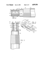
- FIG. 3 is a side view of the present invention.
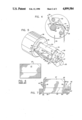
- FIG. 4 is a sectional end view of the embodiment of FIG. 3 taken along cutting plane 4--4;
- FIG. 5 is a rotated perspective view of the invention of FIG. 3;
- FIG. 6 is a baffle of the prior art in developed form
- FIG. 7 is the baffle of the present invention in developed form.
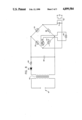
- FIG. 8 is a basic circuit diagram with which the heater and sensor probes of the invention could be connected.
- Housing 11 is typically provided with threads 12 by means of which the housing is connected in the side wall of a container or conduit. Housing 11 may contain the electronic circuitry shown in FIG. 8 in addition to providing a mounting means for the heater and sensor elements. Extending parallel to the longitudinal axis of the housing, from end face 13 of cylindrical extension 18, are heater element probe 14, reference sensor probe 15 and active sensor probe 16. The external elements of the sensor probes are thermowells enclosing sensors such as resistance temperature detectors. The purposes and functions of each of these elements is described in previously mentioned U.S. Pat. Nos. 3,366,942 and 3,898,638 so they need not be discussed in detail here.
- Deflector vane or baffle 17 is secured to mounting brackets 21 and 22 along upper bridge surface 23 extending between them by brazing 28 or by other suitable means. Brackets 21 and 22 extend between and are secured to sensor probes 15 and 16. Further support for bracket 22 is provided by reverse bend 22a which is brazed to end face 13. The opposite edges of vane 17 between and closely adjacent brackets 21 and 22 are secured to the respective brackets by brazing 29 and 30.
- baffle 17 of the prior art sensor is literally torn from its mounting brackets.
- Another stress factor is the existence of water hammers caused by the use of reciprocating pumps operating at high speeds to improve oil well production rates. There may well be other causes of sudden force being applied to the baffle.
- FIGS. 3-5 and 7 Much like the prior art device shown in FIGS. 1 and 2, the invention of FIGS. 3-5 and 7 has reference sensor 24, active sensor 25 and heater 26, only the external shields of which are shown.
- Baffle 27 is secured to the device, typically by means of bracket members 31 and 32 mounted to the sensors. Bracket members 31 and 32 are bridged by strap member 33. Bracket 32 is formed with reverse bend portion 34 which is closely adjacent or in contact with face 35 of cylindrical extension 36 of housing 37.
- bracket members 31 and 32 are formed with holes through which sensor shields 24 and 25 extend. Bracket members 31 and 32 are then anchored to the respective sensor housings by such means as brazing. Additionally, bend portion 34 is secured such as by brazing to face 35 of the housing.
- the sensor of this invention is frequently required to detect flow in relatively small pipes with a small clear flow area. Because of the typical size limitations, there is a very restricted area available for bracing or reinforcing the sensor baffle to prevent it from being destroyed. It was therefore deemed to be necessary to obtain the desired reinforcement without presenting an externally enlarged structure which could further affect or impede fluid flow.
- Baffle 27 is secured to the sensor end of housing 37 by means of several elements to enable it to withstand stress from high flow velocities, water hammers and the like and continue to perform its intended function.
- Base 38 of the baffle is closely adjacent and parallel with strap 33 and is secured thereto by such means as brazing 39.
- Tab 41 is an extension of base 38 farthest from face 35 of the housing, and is bent to extend over the external portion of bracket member 31 is and secured thereto.
- tab 42 extends beyond the flat upper side of strap 33 toward face 35. This tab is parallel with base 38 or it may be bent slightly downward and is secured to the upper portion of bend 34, and to face 35 of the housing, by such means as brazing.
- Baffle 27 is bent inwardly toward heater element 26 at bend line 40 (FIG.
- baffle 27 extends beyond the width of strap 33. It also extends generally toward active sensor 25. Flap portions 43 and 44 of baffle 27 are bent upwardly in a direction opposite to the direction of bend of the baffle from base 38. These flaps are secured to the inside or facing sides of bracket members 31 and 32 by such means as brazing, as shown in the drawing. A further tab 45 extends from base 38 of baffle 27 just forward of tab 42, is bent down to a position parallel with a portion of bracket member 32 and is secured thereto by such means as brazing. The distal end of baffle 27 is formed with focusing flaps 46 and 47 as shown.
- baffle 27 The forces acting on the sensor from flowing fluid can be seen in FIG. 4. With general flow direction indicated by arrow 76, significant forces can be applied to baffle 27. In the prior art unreinforced baffle only edge connections 29 and 30 added to the face braze connection 28 to bridge surface 23. When fluid flow forces become great, the edge brazes tend to tear loose and the resultant torque applied to baffle 17 results in destruction of the baffle/bridge structure.
- the invention adds compressive tabs 43 and 44 which serve to greatly enhance the strength of the mounting of baffle 27 to brackets 31 and 32.
- Tab 45 is more of a tension member while tabs 41 and 42 are anchoring members between base 38 of the baffle and bridge member 33.
- the baffle of the invention is shown developed in FIG. 7 and may be compared with the representation of the prior art baffle in FIG. 6.
- Bend lines 81 and 82 for tabs 43 and 44 are shown in line with outside edges 83 and 84 of the baffle.
- bend line 85 for tab 41 is parallel but spaced from edge 83 and bend line 81 by the thickness of bracket 31.
- bend line 86 is parallel but spaced from edge 84 and bend line 82 by the thickness of bracket 32.
- Space 87 between tabs 42 and 45 is provided to ensure clearance between the two tabs which connect to bracket 32 differently from each other.
- Collar 51 is secured to heater element 26 in a thermally conductive manner.
- the collar is formed with two tabs 52 extending directly toward active sensor 25. This configuration accentuates the transfer of heat by convection from the heater to the active sensor when the fluid in which the sensors and heater are immersed is quiescent or is flowing below the threshold velocity.
- Changes in flow velocity directly affect the extent to which heat is dissipated and, in turn, the temperature differential between the sensors.
- This differential decreases as flow velocity increases, thereby cooling heated or active sensor 25.
- This differential is electronically converted into an output signal which can be used to provide a predetermined indication at any specified velocity set point. For example, an operator may want to know when fluid flow velocity has dropped below a certain level, whatever that level may be, and commensurately, when fluid is flowing above the critical threshold level.
- This sensor by adjusting the spacing relationship between the heater and the sensor elements and the position and shape of the baffle, as well as the size and location of collar 51 with tabs 52, can be made to show fluid flow only beyond a certain fluid velocity. That flow velocity may be substantially higher than is the expected flow in which the prior art sensor was intended to function.
- the flow threshold may be modified within the circuitry connected to the sensors.
- Another use of the present invention is to determine liquid level in a storage container.
- Several sensors of FIG. 3 may be installed in the side or end of a storage tank at different levels. It is known that the temperature differential between the active and the reference sensors is different when the heater and sensors are in still air as opposed to when they are in still fluid. Thus it is possible to determine whether or not both sensors are immersed or are dry. Alternatively, if the fluid level has reached the reference sensor only, and not the active sensor, there would be another characteristic temperature differential between them. In this way, with one or several such sensors in a tank, liquid level can be monitored. Of course it is possible to use only one such sensor at a critical level about which the operator wants to know certain facts. A single sensor may be able to provide sufficient information for certain purposes. All process media exhibit different abilities to transfer heat. Thus the instrument can be specifically calibrated to sense an interface between any immiscible products, including liquids, gases, slurries and foam, regardless of their other physical properties.
- the circuit of FIG. 8 is a simplified diagram showing the basic electrical circuitry which may accompany the sensor and heater configuration shown. Of course, many other circuit configurations are possible, and the circuit may be much more sophisticated if desired.
- the circuit comprises a power source 61 which may be a conventional source of 110 volt AC. If desired, the incoming current may be converted to DC.
- the circuit also includes a common line isolation transformer 62, a typical rectifier 63 which is a semiconductor diode which, acting through resistor 64, serves to rectify the high frequency pulses and thereby charge capacitor 65 with a fixed polarity.
- a Wheatstone bridge is formed as part of the circuit and includes the resistance wire temperature sensors of probes 24 and 25 balanced against fixed resistance 66 and variable resistance 67, respectively.
- Voltmeter 71 may be connected across the bridge to give a visual indication when the bridge becomes unbalanced or it may be placed across sensor element 25, which may be a thermistor, to directly measure the temperature of the material in which it is immersed.
- the voltmeter may equally be a galvanometer, ohmmeter or other suitable current or voltage detecting or measuring device which may be connected across the bridge to give the desired visual indication.
- relay switch 72 may also be connected across the bridge. Leads 73 from the relay switch may be connected to any desired auxiliary warning device, such as a light or an alarm, or to a secondary operational circuit, such as one activating a standby pump or automated valve system or the like.
- a separate source 68 of current for heater 26 is shown although power source 61 could easily be used to power the heater also. The functional aspects of the invention have been described and it is believed to not be necessary to describe the operation of the FIG. 8 circuit detail in conjunction with the sensors and heater.
- baffle 17 of FIG. 1 is secured primarily by means of brazing 28 along strap 23 bridging bracket elements 21 and 22 with only opposite edges brazed for a short distance along the sides of the deflector vane as they lie closely adjacent the inside surfaces of brackets 21 and 22.
- relatively high flow velocities of the fluid in which the sensor is immersed could cause the baffle aspect of the sensor to be torn off and its effect to be destroyed.
Landscapes
- Physics & Mathematics (AREA)
- Fluid Mechanics (AREA)
- General Physics & Mathematics (AREA)
- Thermal Sciences (AREA)
- Measuring Volume Flow (AREA)
Abstract
Description
Claims (11)
Priority Applications (1)
| Application Number | Priority Date | Filing Date | Title |
|---|---|---|---|
| US07/265,786 US4899584A (en) | 1988-10-31 | 1988-10-31 | Fluidic amplifier for sensing fluid motion |
Applications Claiming Priority (1)
| Application Number | Priority Date | Filing Date | Title |
|---|---|---|---|
| US07/265,786 US4899584A (en) | 1988-10-31 | 1988-10-31 | Fluidic amplifier for sensing fluid motion |
Publications (1)
| Publication Number | Publication Date |
|---|---|
| US4899584A true US4899584A (en) | 1990-02-13 |
Family
ID=23011882
Family Applications (1)
| Application Number | Title | Priority Date | Filing Date |
|---|---|---|---|
| US07/265,786 Expired - Fee Related US4899584A (en) | 1988-10-31 | 1988-10-31 | Fluidic amplifier for sensing fluid motion |
Country Status (1)
| Country | Link |
|---|---|
| US (1) | US4899584A (en) |
Cited By (12)
| Publication number | Priority date | Publication date | Assignee | Title |
|---|---|---|---|---|
| EP0510663A1 (en) * | 1991-04-25 | 1992-10-28 | Trilog Entwicklungsgesellschaft für Mehrwegsysteme GmbH | Device for detecting a liquid or a gas |
| US5780737A (en) * | 1997-02-11 | 1998-07-14 | Fluid Components Intl | Thermal fluid flow sensor |
| US5913250A (en) * | 1997-10-29 | 1999-06-15 | Fluid Components Intl | Pressure compensated thermal flow meter |
| US6208254B1 (en) | 1999-09-15 | 2001-03-27 | Fluid Components Intl | Thermal dispersion mass flow rate and liquid level switch/transmitter |
| US6340243B1 (en) * | 1998-12-03 | 2002-01-22 | Fluid Components Intl | Liquid/gas phase detector system |
| US20040055900A1 (en) * | 2002-09-23 | 2004-03-25 | Siemens Westinghouse Power Corporation | Apparatus and methods for sampling and analyzing inlet air associated with combustion turbine |
| US20060048568A1 (en) * | 2004-09-08 | 2006-03-09 | Oleg Korniyenko | Thermal mass flow sensor |
| US8360635B2 (en) * | 2007-01-09 | 2013-01-29 | Schlumberger Technology Corporation | System and method for using one or more thermal sensor probes for flow analysis, flow assurance and pipe condition monitoring of a pipeline for flowing hydrocarbons |
| US9528868B2 (en) | 2014-12-17 | 2016-12-27 | Fluid Components International Llc | Dual sensor head configuration in a fluid flow or liquid level switch |
| US10036143B2 (en) | 2011-01-03 | 2018-07-31 | Sentinel Hydrosolutions, Llc | Non-invasive thermal dispersion flow meter with fluid leak detection and freeze burst prevention |
| US11814821B2 (en) | 2011-01-03 | 2023-11-14 | Sentinel Hydrosolutions, Llc | Non-invasive thermal dispersion flow meter with fluid leak detection and geo-fencing control |
| US12098916B1 (en) * | 2021-03-22 | 2024-09-24 | The United States Of America, As Represented By The Secretary Of The Navy | Temperature sensing arrayal for freeboard detection |
Citations (3)
| Publication number | Priority date | Publication date | Assignee | Title |
|---|---|---|---|---|
| US3366942A (en) * | 1966-07-21 | 1968-01-30 | Robert A. Deane | Flow stoppage detector |
| US3898638A (en) * | 1973-08-09 | 1975-08-05 | Robert A Deane | Differential temperature sensor system and improvements in a fluid flow detector |
| US4774833A (en) * | 1986-11-04 | 1988-10-04 | Vdo Adolf Schindling Ag | Device for determining mass flow and direction of flow |
-
1988
- 1988-10-31 US US07/265,786 patent/US4899584A/en not_active Expired - Fee Related
Patent Citations (3)
| Publication number | Priority date | Publication date | Assignee | Title |
|---|---|---|---|---|
| US3366942A (en) * | 1966-07-21 | 1968-01-30 | Robert A. Deane | Flow stoppage detector |
| US3898638A (en) * | 1973-08-09 | 1975-08-05 | Robert A Deane | Differential temperature sensor system and improvements in a fluid flow detector |
| US4774833A (en) * | 1986-11-04 | 1988-10-04 | Vdo Adolf Schindling Ag | Device for determining mass flow and direction of flow |
Non-Patent Citations (1)
| Title |
|---|
| Catalog of Fluid Components, Inc. (1986). * |
Cited By (14)
| Publication number | Priority date | Publication date | Assignee | Title |
|---|---|---|---|---|
| EP0510663A1 (en) * | 1991-04-25 | 1992-10-28 | Trilog Entwicklungsgesellschaft für Mehrwegsysteme GmbH | Device for detecting a liquid or a gas |
| US5780737A (en) * | 1997-02-11 | 1998-07-14 | Fluid Components Intl | Thermal fluid flow sensor |
| US5913250A (en) * | 1997-10-29 | 1999-06-15 | Fluid Components Intl | Pressure compensated thermal flow meter |
| US6340243B1 (en) * | 1998-12-03 | 2002-01-22 | Fluid Components Intl | Liquid/gas phase detector system |
| US6208254B1 (en) | 1999-09-15 | 2001-03-27 | Fluid Components Intl | Thermal dispersion mass flow rate and liquid level switch/transmitter |
| US6628202B2 (en) | 1999-09-15 | 2003-09-30 | Fluid Components Intl | Thermal dispersion mass flow rate and liquid level switch/transmitter |
| US20040055900A1 (en) * | 2002-09-23 | 2004-03-25 | Siemens Westinghouse Power Corporation | Apparatus and methods for sampling and analyzing inlet air associated with combustion turbine |
| US20060048568A1 (en) * | 2004-09-08 | 2006-03-09 | Oleg Korniyenko | Thermal mass flow sensor |
| US7107835B2 (en) * | 2004-09-08 | 2006-09-19 | Honeywell International Inc. | Thermal mass flow sensor |
| US8360635B2 (en) * | 2007-01-09 | 2013-01-29 | Schlumberger Technology Corporation | System and method for using one or more thermal sensor probes for flow analysis, flow assurance and pipe condition monitoring of a pipeline for flowing hydrocarbons |
| US10036143B2 (en) | 2011-01-03 | 2018-07-31 | Sentinel Hydrosolutions, Llc | Non-invasive thermal dispersion flow meter with fluid leak detection and freeze burst prevention |
| US11814821B2 (en) | 2011-01-03 | 2023-11-14 | Sentinel Hydrosolutions, Llc | Non-invasive thermal dispersion flow meter with fluid leak detection and geo-fencing control |
| US9528868B2 (en) | 2014-12-17 | 2016-12-27 | Fluid Components International Llc | Dual sensor head configuration in a fluid flow or liquid level switch |
| US12098916B1 (en) * | 2021-03-22 | 2024-09-24 | The United States Of America, As Represented By The Secretary Of The Navy | Temperature sensing arrayal for freeboard detection |
Similar Documents
| Publication | Publication Date | Title |
|---|---|---|
| US3366942A (en) | Flow stoppage detector | |
| US4899584A (en) | Fluidic amplifier for sensing fluid motion | |
| JP5079492B2 (en) | Annular capacitive pressure sensor | |
| US3438254A (en) | Fluid flow detector | |
| US4862734A (en) | Leak detection system for storage tanks | |
| US20060248961A1 (en) | Flow sensor and fire detection system utilizing same | |
| EP1800044B1 (en) | Arrangement or provision of a sensor or probe for the measuring of a condition in a pipe or the like | |
| RU2286544C2 (en) | Measuring transformer of vortex-type flow | |
| EP3625542B1 (en) | Apparatus that measures deflection at multiple points to determine flow rate | |
| JP2023531184A (en) | Undersea multivariable transmitter | |
| EP0158745A1 (en) | Flow meter and densitometer apparatus and method of operation | |
| Boyce | Transport and storage of fluids | |
| US4612814A (en) | Flow meter and densitometer apparatus | |
| CN101512297B (en) | Leak Check Set for Eddy Current Detector Replacement | |
| US20060042363A1 (en) | Method for detecting corrosion in industrial process equipment | |
| CA2511748C (en) | Flow measuring method and device | |
| EP0130653B1 (en) | Flow meter and densitometer apparatus and method of operation | |
| EP2320199B1 (en) | A method of detecting slugs of one phase in a multiphase flow | |
| EP1943494B1 (en) | Monitoring particles in a fluid stream | |
| Trevathan | Process Instrumentation | |
| CN111121989A (en) | Fluid detection device | |
| US20250180164A1 (en) | Condensate drain, sensor device, and method for detecting the state of a flow path | |
| RU2121662C1 (en) | Method of measurement of liquid flow rate and continuity | |
| Gillum | Process Transmitters | |
| Liptak et al. | Overview of coal conversion process instrumentation |
Legal Events
| Date | Code | Title | Description |
|---|---|---|---|
| AS | Assignment |
Owner name: FLUID COMPONENTS, INC., 1755 LA COSTA MEADOWS DR., Free format text: ASSIGNMENT OF ASSIGNORS INTEREST.;ASSIGNOR:MC QUEEN, MALCOLM M.;REEL/FRAME:004970/0907 Effective date: 19881028 Owner name: FLUID COMPONENTS, INC., CALIFORNIA Free format text: ASSIGNMENT OF ASSIGNORS INTEREST;ASSIGNOR:MC QUEEN, MALCOLM M.;REEL/FRAME:004970/0907 Effective date: 19881028 |
|
| FEPP | Fee payment procedure |
Free format text: PAYOR NUMBER ASSIGNED (ORIGINAL EVENT CODE: ASPN); ENTITY STATUS OF PATENT OWNER: SMALL ENTITY |
|
| FPAY | Fee payment |
Year of fee payment: 4 |
|
| AS | Assignment |
Owner name: FLUID COMPONENTS INTL, CALIFORNIA Free format text: ASSIGNMENT OF ASSIGNORS INTEREST;ASSIGNOR:FLUID COMPONENTS, INC.;REEL/FRAME:007869/0424 Effective date: 19950925 |
|
| REMI | Maintenance fee reminder mailed | ||
| LAPS | Lapse for failure to pay maintenance fees | ||
| FP | Lapsed due to failure to pay maintenance fee |
Effective date: 19980218 |
|
| STCH | Information on status: patent discontinuation |
Free format text: PATENT EXPIRED DUE TO NONPAYMENT OF MAINTENANCE FEES UNDER 37 CFR 1.362 |