US4899388A - Infrared stereo speaker system - Google Patents
Infrared stereo speaker system Download PDFInfo
- Publication number
- US4899388A US4899388A US07/143,588 US14358888A US4899388A US 4899388 A US4899388 A US 4899388A US 14358888 A US14358888 A US 14358888A US 4899388 A US4899388 A US 4899388A
- Authority
- US
- United States
- Prior art keywords
- signal
- analog
- converting
- infrared
- selecting
- Prior art date
- Legal status (The legal status is an assumption and is not a legal conclusion. Google has not performed a legal analysis and makes no representation as to the accuracy of the status listed.)
- Expired - Fee Related
Links
- 230000005236 sound signal Effects 0.000 claims abstract description 37
- 230000005540 biological transmission Effects 0.000 claims abstract description 12
- 238000001914 filtration Methods 0.000 claims description 5
- 239000003990 capacitor Substances 0.000 description 28
- 230000003321 amplification Effects 0.000 description 4
- 238000003199 nucleic acid amplification method Methods 0.000 description 4
- 230000001052 transient effect Effects 0.000 description 4
- 238000006243 chemical reaction Methods 0.000 description 3
- 230000006835 compression Effects 0.000 description 3
- 238000007906 compression Methods 0.000 description 3
- 238000010586 diagram Methods 0.000 description 3
- 238000010276 construction Methods 0.000 description 1
- 238000009434 installation Methods 0.000 description 1
- 230000001105 regulatory effect Effects 0.000 description 1
Images


Classifications
-
- H04B5/22—
-
- H—ELECTRICITY
- H04—ELECTRIC COMMUNICATION TECHNIQUE
- H04B—TRANSMISSION
- H04B10/00—Transmission systems employing electromagnetic waves other than radio-waves, e.g. infrared, visible or ultraviolet light, or employing corpuscular radiation, e.g. quantum communication
- H04B10/11—Arrangements specific to free-space transmission, i.e. transmission through air or vacuum
- H04B10/114—Indoor or close-range type systems
-
- H—ELECTRICITY
- H04—ELECTRIC COMMUNICATION TECHNIQUE
- H04B—TRANSMISSION
- H04B10/00—Transmission systems employing electromagnetic waves other than radio-waves, e.g. infrared, visible or ultraviolet light, or employing corpuscular radiation, e.g. quantum communication
-
- H—ELECTRICITY
- H04—ELECTRIC COMMUNICATION TECHNIQUE
- H04B—TRANSMISSION
- H04B5/00—Near-field transmission systems, e.g. inductive loop type
-
- H—ELECTRICITY
- H04—ELECTRIC COMMUNICATION TECHNIQUE
- H04R—LOUDSPEAKERS, MICROPHONES, GRAMOPHONE PICK-UPS OR LIKE ACOUSTIC ELECTROMECHANICAL TRANSDUCERS; DEAF-AID SETS; PUBLIC ADDRESS SYSTEMS
- H04R3/00—Circuits for transducers, loudspeakers or microphones
-
- H—ELECTRICITY
- H04—ELECTRIC COMMUNICATION TECHNIQUE
- H04W—WIRELESS COMMUNICATION NETWORKS
- H04W52/00—Power management, e.g. TPC [Transmission Power Control], power saving or power classes
- H04W52/02—Power saving arrangements
- H04W52/0209—Power saving arrangements in terminal devices
- H04W52/0225—Power saving arrangements in terminal devices using monitoring of external events, e.g. the presence of a signal
-
- H—ELECTRICITY
- H04—ELECTRIC COMMUNICATION TECHNIQUE
- H04R—LOUDSPEAKERS, MICROPHONES, GRAMOPHONE PICK-UPS OR LIKE ACOUSTIC ELECTROMECHANICAL TRANSDUCERS; DEAF-AID SETS; PUBLIC ADDRESS SYSTEMS
- H04R2420/00—Details of connection covered by H04R, not provided for in its groups
- H04R2420/07—Applications of wireless loudspeakers or wireless microphones
-
- Y—GENERAL TAGGING OF NEW TECHNOLOGICAL DEVELOPMENTS; GENERAL TAGGING OF CROSS-SECTIONAL TECHNOLOGIES SPANNING OVER SEVERAL SECTIONS OF THE IPC; TECHNICAL SUBJECTS COVERED BY FORMER USPC CROSS-REFERENCE ART COLLECTIONS [XRACs] AND DIGESTS
- Y02—TECHNOLOGIES OR APPLICATIONS FOR MITIGATION OR ADAPTATION AGAINST CLIMATE CHANGE
- Y02D—CLIMATE CHANGE MITIGATION TECHNOLOGIES IN INFORMATION AND COMMUNICATION TECHNOLOGIES [ICT], I.E. INFORMATION AND COMMUNICATION TECHNOLOGIES AIMING AT THE REDUCTION OF THEIR OWN ENERGY USE
- Y02D30/00—Reducing energy consumption in communication networks
- Y02D30/70—Reducing energy consumption in communication networks in wireless communication networks
Definitions
- This invention relates to loudspeaker systems for converting an electrical signal, originating at an audio amplifier, to an audio signal to be radiated within a listening area, and in particular to such loudspeaker systems which receive their signal from the audio amplifier without any direct connection by wire.
- This invention relates to improvements over the systems described above and to solutions to the problems raised thereby.
- the invention includes a stereophonic audio system including means for providing an electric signal containing stereophonic signal information, such as an audio receiver or amplifier or a stereo television, to name but a few examples.
- a converting means is included in the invention, and comprises means for electrically connecting it to the providing means. The converting means receives the electric signal, converts it to an infrared signal containing the stereophonic signal information, and radiates the infrared signal throughout a signal area.
- a first selecting means say a left loudspeaker, for selecting one portion of the infrared signal, in this case the left signal, converting that one portion of the infrared signal to a first audible sound signal, and radiating the audible sound signal throughout a listening area, which may or may not be co-extensive with the signal area.
- Second selecting means such as a right loudspeaker, is also disposed within the same signal area but separated remotely from the first selecting means. This second selecting means selects a second portion of the infrared signal, in this case the right signal, converts this second portion to a second audible sound signal, and radiates the second audible sound signal throughout the same listening area.
- Each selecting means includes filter means for filtering out any infrared signal other than the one portion which applies to it.
- the providing means includes a stereo audio amplifier providing a left channel signal and a right channel signal and having a headphone jack for allowing connection to both channels.
- the converting means includes a plug engageable with the headphone jack for electrically connecting the converting means to the amplifier and amplifying means for amplifying the left channel signal and the right channel signal. The two signals then modulate the carrier frequencies which are and mixed together to produce a transmission signal, which is radiated by infrared diode means within the signal area.
- Each of the selecting means generally includes a photodiode arrangement for receiving the infrared light carrying the transmission signal from the converting means and passing it to the respective filter means, amplifying means for amplifying the signal from the respective filter means, and at least one speaker means for receiving the signal from the amplifying means and converting it to sound signals, for radiating in the listening area.
- each loudspeaker includes means for selecting the portion of the audio signal that is applicable to itself only, and ignore the rest of the signal.
- a more specific object of the invention is to provide an audio system as set forth above which can be completely battery driven, so that no wires need be attached to the speaker at all to hinder or otherwise affect its placement in the listening area.
- Another specific object of the invention is to provide an audio system as described above wherein the batteries are rechargeable by circuitry employed within the speaker enclosure, allowing the user to plug the loudspeaker into a power outlet if desired to extend battery life.
- FIG. 1 is an isometric view of a listening area showing an audio system constructed according to a preferred embodiment of the invention.
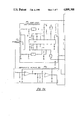
- FIGS. 2A and 2B together make up a schematic circuit diagram of a transmitter constructed according to a preferred embodiment of the invention.
- FIGS. 3A and 3B together make up a schematic circuit diagram of a left loudspeaker constructed according to a preferred embodiment of the invention.
- FIGS. 4A and 4B together make up a schematic circuit diagram of a right loudspeaker constructed according to a preferred embodiment of the invention.
- a stereo receiver or amplifier, or other source 12 of an electronic audio signal is placed within the signal/listening area 10.
- the source 12 includes an outlet for connection of an accessory speaker arrangement, such as a headphone jack 14, positioned conveniently, for instance on the front surface 12a of the source 12.
- the invention further provides for a conversion means 16 for receiving the electrical audio signal from the source 12, converting that signal to an infrared audio signal to be radiated into the signal/listening area 10, and radiating that signal.
- This conversion means 16 will hereafter be referred to as the infrared transmitter or just the transmitter 16 for ease of reference.
- Two separate selecting means 17 and 19 are located within the signal/listening area 10, for receiving the signal from the transmitter 16. These selecting means 17 and 19 will be referred to hereafter as loudspeakers 17 and 19 for easier reference.
- each loudspeaker 17 and 19 selects the portion of the signal which pertains to it, whether it be the left signal or the right signal, converts that signal to sound and radiates that sound into the signal/listening area 10.
- the details of the transmitter 16 can be seen by reference to FIGS. 2A and 2B, while the details of the loudspeakers can be seen by reference to FIGS. 3A, 3B, 4A and 4B.
- transmitter 16 is shown to include a plug 18 or other attachment means for electrically connecting the transmitter to the source 12, as referred to above, that is, by inserting plug 18 into jack 14 (FIG. 1) of the source.
- transmitter 16 receives the electrical audio signal, in both left and right channels, from the source 12.
- the signal enters a compression and pre-amplification circuit 20, where the signal is pre-amplified and compressed for more efficient and noise-free transmission.
- the compression is accomplished mainly by an integrated circuit IC1, referred to as a compander. Any suitable integrated circuit may be employed as IC1, such as the Signetics NE570N.
- Each channel processing means 22 and 24 includes a power input indicator circuit 26 (left) and 28 (right) respectively.
- the purpose of these power input indicator 26 and 28 circuits is to provide some indication of the level of input into the transmitter. That is, if the power input level is too high, an LED power indicator circuit 60 will drive an indicator LED 62 to shine brightly, and return to a normal intensity upon reduction of the input signal to normal levels.
- Each channel processing means 22 and 24 further includes a matching amplifier 30 (left) and 32 (right) for impedance matching purposes and an automatic gain control circuit 34 (left) and 36 (right).
- each channel signal modulates a carrier signal by means of an FM modulator circuit 38 (left) and 40 (right) still within the channel processing means 22 and 24.
- the carrier for the left channel is preferably in the area of 95 KHz while the carrier for the right channel is preferably approximately 250 KHz.
- the signals are sent to a carrier frequency limiter/mixer 42, where the signals are "mixed", that is, combined together to permit transmission in a single transmission signal.
- the transmission signal passes to the infrared light emitting diode (LED) array 44, via an infrared output driver 46.
- the LEDs are powered by the driver 46 so as to transmit the mixed signal by means of infrared light.
- the transmitter 16 is powered by an AC adapter 48 which connects to a regular AC receptacle (not shown).
- the output of the adapter 48 is preferably 24 volts, and connects to a power jack 50, which is part of the transmitter 16. From the power jack 50, power passes through a switch 52, by which a user may turn the transmitter 16 on or off.
- a power regulating circuit 54 conditions the power from the switch before it is sent into the rest of the transmitter 16.
- the preferred embodiment of the transmitter 16 includes an automatic shut-off circuit 56.
- This circuit 56 monitors the incoming electrical audio signal, and in this case the left channel thereof.
- the automatic stand-by circuit 56 effectively switches the transmitter 16 into a stand-by mode by use of a stand-by control circuit 58, effectively disabling the LED array 44.
- the length of the interval is determined by the values of the components. In this case the interval is determined at about 45 seconds.
- the purpose and operation of the stand-by control circuit 58 will be set forth in more detail in connection with the description of the circuitry of the loudspeakers.
- the LED power indicator circuit 60 does drive the LED indicator 62 to indicate an over-power condition as described above, its main purpose is to indicate when power is applied to the transmitter 16 via the power switch 52.
- the indicator LED 62 remains on regardless of the state of the stand-by control 58, whenever the transmitter power switch 52 is on.
- the infrared signal from the transmitter 16 is radiated throughout the signal/listening area 10.
- Each loudspeaker 17 and 19 has a receiving means 64 and 66 respectively for receiving the infrared signal, and for selecting which portion of the signal applies to it.
- FIGS. 3A and 3B the detail of the loudspeakers 17 and 19 is shown at FIGS. 3A and 3B, for left loudspeaker 17, and at FIGS. 4A and 4B, for right loudspeaker 19.
- the signal from the transmitter 16 is received by receiving means 64, which in the preferred embodiment comprises a pair of photosensitive diodes 68. These diodes 68 react to infrared light to produce a received electrical signal corresponding to the transmission signal referred to above within the transmitter 16.
- the reason two diodes 68 are used is tat each diode 68 can only receive a signal on one side, that is, from one direction.
- two diodes 68 are used, and are arranged physically back-to-back.
- the signal received by the two diodes 68 is then sent to a radio-frequency (RF) pre-amplifier 70 for pre-amplification.
- RF radio-frequency
- the signal is sent to a band pass filter 72.
- This band pass filter 72 is provided to enable the loudspeaker 17 to select the particular electrical audio signal at the predetermined carrier frequency which applies to it and exclude all other signals.
- the selected carrier frequency is the 95 KHz frequency referred to above for the left channel.
- the band pass filter 72 is accomplished by the particular arrangement of the band pass filter 72 and the values of its components. This arrangement of components, each followed by the respective preferred value, is as follows. The values given are only preferred, since other values may be possible to accomplish the same function within the spirit of the present invention.
- the signal is first sent to a resistor R1 (2.2K ohm) and a capacitor C1 (0.002 ufd) in series.
- the signal passes over a resistor R2 (10K ohm), a capacitor C2 (600 pfd) and an inductor L1 (4.7 mH), arranged in parallel between the output of C1 and ground.
- the signal passes through a parallel arrangement of an inductor L2 (4.7 mH) and a capacitor C3 (82 pfd). Finally, the signal passes over a capacitor C4 (330 pfd) arranged between the output of the L2-C3 arrangement and ground, and through another capacitor C5 (330 pfd) to exit the band pass filter 72.
- the signal From the band pass filter 72 the signal, now filtered so as to only have the 95 KHz carrier, having had the 250 KHz carrier and its accompanying audio signal removed, passes to an intermediate frequency (IF) amplifier 74 for further amplification of the selected signal.
- the main functional element of the IF amplifier 74 is an integrated circuit IC2, which is preferred to be a Syllax Model 111-0204 integrated circuit.
- the signal enters from the band pass filter 72 at pin 14 of IC2. Pins 1, 3, 4, 5 and 12 are grounded. Pin 14 is connected to pin 13 by a resistor R3 (4.7K Ohm). In addition, pin 2 is connected to pin 13 by a capacitor C6 (47 ufd). Pin 13 is in turn connected to ground via a capacitor C7 (10 ufd).
- Pin 11 is connected to a power supply/indication circuit 76, the detail of which will be set forth later in this description.
- Pin 8 is connected to pin 11 by a capacitor C8 (0.0068 ufd) and to an expander/audio preamplifier circuit 78 by a filter circuit 80.
- filter circuit 80 includes a capacitor C9 (2.2 ufd) in series with a resistor R4 (2.2K ohm), and a capacitor C10 (0.002 ufd) connected between the output of the resistor R4 and ground.
- Pins 9 and 10 are connected by a capacitor C11 while, similarly, pins 6 and 7 are connected by a capacitor C12. In the left loudspeaker 17, the values of both capacitors C11 and C12 are preferred to be 820 pfd.
- pins 7 and 9 are connected by a resistor R5 (3.9K ohm) and an adjustable coil L3.
- the audio signal passes from the IF amplifier 74 into the expander/audio pre-amplifier 78.
- the purpose of this circuit is to expand the signal which was compressed by the compressor/pre-amplifier circuit 20 of the transmitter 16, shown in FIG. 2.
- the main functional element of the expander/audio pre-amplifier circuit 78 is another compander integrated circuit IC3, which is preferably another Signetics NE570N integrated circuit, similar to the one used in the transmitter 16.
- the signal passes to a tone and volume control 82, then to an audio power output amplifier 84 and finally to speaker elements 86 and 88.
- speaker elements 86 and 88 In the embodiment shown in FIG. 3, two such speaker elements are shown, although any suitable number in any suitable combination of types may be used, as is well known in the art of loudspeaker construction.
- Speaker element 86 is shown to be a tweeter, while speaker element 88 is a woofer.
- control of the tone of the audio signal is accomplished by a variable resistor R6, while control of the volume is accomplished by use of another variable resistor R7.
- a power supply 76 includes a self contained power source 90 of preferably 12 volts, such as eight conventional "D" cells.
- the power supply 76 further includes a generally conventional power regulator 92, and is controlled by a suitable switch means 94.
- a charging receptacle 96 is provided in the preferred embodiment so as to allow the user to recharge the batteries 90 rather than simply replace them, to reduce the cost of use of the loudspeaker 17.
- a power saver means 98 in the loudspeaker 17 for cutting battery drain in response to a loss of carrier due to the transmitter 16 disabling its LED array 44. That way, when the transmitter 16 senses that it is no longer receiving a signal from the audio signal source 12, meaning that the receiver or amplifier has probably been turned off without the transmitter and speakers having been turned off, the transmitter disables the LED array 44. Upon the LED array 44 being disabled, the loudspeaker 17 no longer receives an LED signal.
- the power saver means 98 cuts power to the audio power output amplifier 84, which is the main power user within the loudspeaker. Later, when the signal is resumed, the LED array 44 of the transmitter 16 is re-enabled and the signal transmitted to the loudspeaker 17, which in turn results in the power saver means 98 reconnecting power to the audio power output amplifier 84.
- the power saver means 98 includes an RF amplifier 100 for receiving a signal from the output of the band pass filter 72 and further amplifying it.
- the power saver means 98 further includes a muting control circuit 102, which receives the amplified RF signal from the RF amplifier 100.
- the muting control circuit 102 does not affect the operation of the audio portion of the loudspeaker 17.
- the muting control circuit 102 outputs an interrupt signal as follows.
- the signal from the RF amplifier 100 passes through an RC filter comprising a resistor R8 (4.7K Ohm) and a capacitor C13 (0.001 uF) before reaching the minus input of a comparator 112.
- the level of the plus input of the comparator 112 is controlled by a voltage divider network including a resistor R9 (330K Ohm) between the source and the input and a variable resistor R10 (max. 2.2K Ohm) between the input and ground.
- the minus input of comparator 112 is further filtered by another RC filter network including a resistor R11 (10K Ohm)and a capacitor C14 (820 pfd).
- the comparator 112 issues a signal via its output terminal.
- This signal is sent to a transistor network 114, which shunts the audio signal from the expander/audio pre-amplifier circuit 78 to the tone and volume controls R6 and R7, after a suitable time delay to ensure that the interruption is not transient.
- the signal from the output of the comparator 112 is also sent to a power interrupt circuit 104, which is part of the power supply 76.
- the signal is sent via an arrangement of a transistor Q1 and a diode D1, and via suitable delay circuitry to again ensure that the interruption is not transient, to the plus input of a comparator 116, the level of the minus input being determined by a voltage divider comprising two resistors R12 (1 MegOhm) and R13 (150K Ohm)
- the comparator 116 then sends an output signal via a current limiting resistor R14 to a transistor Q2, which in turn controls another transistor Q3.
- Transistor Q3 controls connection of power to audio power output amplifier 84 and expander/audio pre-amp 78. Hence, when the carrier is interrupted, amplifier 84 is powered down.
- the length of the time delay is determined by the values of the components, with the preferred time delay being about 30 seconds.
- a power-on delay regulator 106 interjects a very short delay, usually on the order of about three seconds, before allowing power to get through to the amplifier itself.
- the purpose for this is that the short delay gives the other components time to stabilize before actually sending an audio signal to the speaker elements 86 and 88. This eliminates a transient but aesthetically objectionable spurt of noise which would otherwise issue from the loudspeaker 17 on power up.
- a status indicator 95 is included in the power supply 76, including an LED D2 for indicating the status of the loudspeaker circuit.
- the LED When the power is off by the switch 96, the LED will be off. When the power is on, the LED will be on at a steady but intermediate brightness. When charging, the LED will be on a more intense brightness. When in standby mode, that is when power to the audio power output amplifier 84 is interrupted as described above, the LED will be on at a steady but very dim intensity. When the power source 90 is in need of charging, the LED will flash dimly. When the power source 90 is over charged, the LED will flash brightly.
- loudspeaker 19 is substantially similar to the structure and operation of loudspeaker 17, with the exception of the structure of the band pass filter and portions of the IF amplifier, and certain values of resistors and capacitors in other parts of the circuit.
- the reason for these differences is that the carrier for the right channel, as set forth above, is 250 kHz, rather than the 95 kHz carrier of the left channel.
- the values of certain of the components must be adjusted to accommodate the different carrier.
- the selection of the proper carrier value is again accomplished by the particular arrangement and values of the components a band pass filter 108 which receives a signal from the RF pre-amplifier 70.
- This arrangement of components, each followed by the respective preferred value, is as follows. The values given are only preferred, since other values may be possible to accomplish the same function within the spirit of the present invention.
- the signal is first sent to a resistor R21 (3.9K ohm) and a capacitor C21 (0.001 ufd) in series.
- the signal passes over a resistor R22 (6.8K ohm) connected to ground, to a capacitor C22 (470 pfd).
- the signal then passes over an inductor L11 (1 mH) connected to ground and on through a capacitor C23 (330 pfd), over a capacitor C24 (0.0015 ufd) connected to ground, through an inductor L12 (1 mH), over yet another capacitor C25 (470 pfd) connected to ground and finally through a capacitor C26 (470 pfd) to exit the band pass filter 108.
- the signal from the band pass filter 108 is fed to an IF amplifier 110.
- the main filter 108 is fed to an IF amplifier 110.
- the main functional component of the IF amplifier 110 is integrated circuit IC2, the same as in left loudspeaker 17, that is, preferably a Syllax Model 111-0204 integrated circuit.
- the various pins of IC2 are connected as described above for the left loudspeaker 17 with the following exceptions.
- Pin 8 while again being connected to pin 11 by the capacitor C8, is connected to the expander/audio pre-amplifier 78 solely by the capacitor C9, without the rest of the filter 80 contained in left loudspeaker 17.
- pins 9 and 10 are connected together by capacitors C27, while pins 6 and 7 are connected together by capacitors C28.
- the values are 300 pfd rather than the 820 pfd specified for capacitors C11 and C12 of FIG. 3.
- the pins 7 and 9 are connected together only by an adjustable inductor L3, there being no resistor corresponding to resistor R5 of FIG. 3.
Abstract
Description
Claims (8)
Priority Applications (3)
| Application Number | Priority Date | Filing Date | Title |
|---|---|---|---|
| US07/143,588 US4899388A (en) | 1988-01-13 | 1988-01-13 | Infrared stereo speaker system |
| CA000588021A CA1287373C (en) | 1988-01-13 | 1989-01-12 | Infrared stereo speaker system |
| KR1019890000273A KR960014409B1 (en) | 1988-01-13 | 1989-01-12 | Infrared stereo speaker system |
Applications Claiming Priority (1)
| Application Number | Priority Date | Filing Date | Title |
|---|---|---|---|
| US07/143,588 US4899388A (en) | 1988-01-13 | 1988-01-13 | Infrared stereo speaker system |
Publications (1)
| Publication Number | Publication Date |
|---|---|
| US4899388A true US4899388A (en) | 1990-02-06 |
Family
ID=22504720
Family Applications (1)
| Application Number | Title | Priority Date | Filing Date |
|---|---|---|---|
| US07/143,588 Expired - Fee Related US4899388A (en) | 1988-01-13 | 1988-01-13 | Infrared stereo speaker system |
Country Status (3)
| Country | Link |
|---|---|
| US (1) | US4899388A (en) |
| KR (1) | KR960014409B1 (en) |
| CA (1) | CA1287373C (en) |
Cited By (39)
| Publication number | Priority date | Publication date | Assignee | Title |
|---|---|---|---|---|
| US5095382A (en) * | 1989-03-20 | 1992-03-10 | Sony Corporation | Wireless headphone |
| US5218641A (en) * | 1990-08-14 | 1993-06-08 | Sony Corporation | Wireless receiver |
| US5239295A (en) * | 1990-04-16 | 1993-08-24 | Motorola, Inc. | Serial light interface which also functions as an ambient light detector |
| EP0586075A1 (en) * | 1992-09-03 | 1994-03-09 | Sony Electronics Inc. | Loudspeaker systems |
| WO1994014110A1 (en) * | 1992-12-10 | 1994-06-23 | Threepenny Electronics Corporation | Battery drain reducer |
| US5432858A (en) * | 1992-07-30 | 1995-07-11 | Clair Bros. Audio Enterprises, Inc. | Enhanced concert audio system |
| WO1995033357A1 (en) * | 1994-05-26 | 1995-12-07 | Mb Quart Akustik Und Elektronik Gmbh | Process and equipment for the reproduction of sound signals, and associated control device and sound reproduction device |
| US5483367A (en) * | 1990-12-31 | 1996-01-09 | Goldstar Co., Ltd. | Transmitting and receiving apparatus for a radio headphone |
| US5619582A (en) * | 1996-01-16 | 1997-04-08 | Oltman; Randy | Enhanced concert audio process utilizing a synchronized headgear system |
| US5666422A (en) * | 1994-05-18 | 1997-09-09 | Harrison; Robert W. | Remote speaker for surround-sound applications |
| US5708718A (en) * | 1996-02-22 | 1998-01-13 | Sounds' So Real Accessories, Inc. | Surround sound processor system |
| US5737427A (en) * | 1996-09-09 | 1998-04-07 | Ambourn; Paul R. | Surround sound processor unit |
| US5771441A (en) * | 1996-04-10 | 1998-06-23 | Altstatt; John E. | Small, battery operated RF transmitter for portable audio devices for use with headphones with RF receiver |
| US5818328A (en) * | 1995-10-03 | 1998-10-06 | Audio Enhancement | Method and system for providing improved wireless audio transmission |
| KR19980086312A (en) * | 1997-05-31 | 1998-12-05 | 윤종용 | Wireless components |
| KR19990041812A (en) * | 1997-11-24 | 1999-06-15 | 윤종용 | Computer devices with wireless speakers |
| US5990646A (en) * | 1996-09-06 | 1999-11-23 | Hunter Douglas Inc. | Remotely-controlled battery powered-window covering having power saving receiver |
| WO2000041438A1 (en) * | 1999-01-06 | 2000-07-13 | Recoton Corporation | Rear channel home theater wireless speaker system |
| US6198825B1 (en) * | 1996-04-15 | 2001-03-06 | Narian Daryanani | Wireless speaker circuit |
| US6487296B1 (en) | 1998-09-30 | 2002-11-26 | Steven W. Allen | Wireless surround sound speaker system |
| US20030107478A1 (en) * | 2001-12-06 | 2003-06-12 | Hendricks Richard S. | Architectural sound enhancement system |
| US6580361B2 (en) * | 2000-12-21 | 2003-06-17 | Charles E. Bucher | Low voltage speaker and lighting system |
| USRE38405E1 (en) * | 1992-07-30 | 2004-01-27 | Clair Bros. Audio Enterprises, Inc. | Enhanced concert audio system |
| GB2397186A (en) * | 2003-01-07 | 2004-07-14 | Punch Video Inc | LCD display with an infrared transmission interface for transmitting audio signals in stereo |
| US20060083396A1 (en) * | 2004-10-20 | 2006-04-20 | Te-Wei Kung | Hand-held wireless speaker |
| US20060204017A1 (en) * | 2003-08-22 | 2006-09-14 | Koninklijke Philips Electronics N.V. | Audio/video system for wireless driving of loudspeakers |
| GB2404809B (en) * | 2003-07-28 | 2007-03-07 | Hewlett Packard Development Co | Projection system |
| US20080192942A1 (en) * | 2007-02-12 | 2008-08-14 | Yamkovoy Paul G | Method and apparatus for conserving battery power |
| US20090204731A1 (en) * | 2006-12-21 | 2009-08-13 | Daniel Mulligan | Automatically disabling input/output signal processing based on the required multimedia format |
| US20100310089A1 (en) * | 2009-06-04 | 2010-12-09 | Wavrydr, L.L.C. | System for allowing selective listening on multiple televisions |
| US7995770B1 (en) | 2007-02-02 | 2011-08-09 | Jeffrey Franklin Simon | Apparatus and method for aligning and controlling reception of sound transmissions at locations distant from the sound source |
| US8588432B1 (en) | 2012-10-12 | 2013-11-19 | Jeffrey Franklin Simon | Apparatus and method for authorizing reproduction and controlling of program transmissions at locations distant from the program source |
| US20140022084A1 (en) * | 2012-07-20 | 2014-01-23 | Laszlo Otto Drimusz | Audio system surround acoustic driver powering |
| US20140328598A1 (en) * | 2013-05-02 | 2014-11-06 | I-Fa Chen | Infrared reception circuit and infrared reception method |
| US8938078B2 (en) | 2010-10-07 | 2015-01-20 | Concertsonics, Llc | Method and system for enhancing sound |
| US8995679B2 (en) | 2011-12-13 | 2015-03-31 | Bose Corporation | Power supply voltage-based headset function control |
| US9049513B2 (en) | 2012-09-18 | 2015-06-02 | Bose Corporation | Headset power source managing |
| KR20190086370A (en) * | 2018-01-12 | 2019-07-22 | 다이오드 인코포레이티드 | Stereo audio system and method |
| US11477418B2 (en) | 2020-05-08 | 2022-10-18 | Harris Global Communications, Inc. | Systems and methods for providing a shoulder speaker microphone device with an integrated thermal imaging device |
Citations (5)
| Publication number | Priority date | Publication date | Assignee | Title |
|---|---|---|---|---|
| US3927316A (en) * | 1974-06-07 | 1975-12-16 | Zenith Radio Corp | Wireless speaker system using infra-red link |
| US4405832A (en) * | 1981-05-29 | 1983-09-20 | Peavey Electronics Corp. | Circuit for distorting an audio signal |
| US4513446A (en) * | 1983-02-09 | 1985-04-23 | General Electric Company | Control circuit for a radio transceiver |
| US4621374A (en) * | 1981-12-24 | 1986-11-04 | Itt Industries, Inc. | Circuit arrangement for processing, transmitting, and acoustically reproducing digitized audio-frequency signals |
| US4736461A (en) * | 1984-02-29 | 1988-04-05 | Nippon Telegraph & Telephone Public Corporation | Method of transmitting terminating call signals within a restricted duration and a base station and a portable unit for use in the same |
-
1988
- 1988-01-13 US US07/143,588 patent/US4899388A/en not_active Expired - Fee Related
-
1989
- 1989-01-12 KR KR1019890000273A patent/KR960014409B1/en not_active IP Right Cessation
- 1989-01-12 CA CA000588021A patent/CA1287373C/en not_active Expired - Lifetime
Patent Citations (5)
| Publication number | Priority date | Publication date | Assignee | Title |
|---|---|---|---|---|
| US3927316A (en) * | 1974-06-07 | 1975-12-16 | Zenith Radio Corp | Wireless speaker system using infra-red link |
| US4405832A (en) * | 1981-05-29 | 1983-09-20 | Peavey Electronics Corp. | Circuit for distorting an audio signal |
| US4621374A (en) * | 1981-12-24 | 1986-11-04 | Itt Industries, Inc. | Circuit arrangement for processing, transmitting, and acoustically reproducing digitized audio-frequency signals |
| US4513446A (en) * | 1983-02-09 | 1985-04-23 | General Electric Company | Control circuit for a radio transceiver |
| US4736461A (en) * | 1984-02-29 | 1988-04-05 | Nippon Telegraph & Telephone Public Corporation | Method of transmitting terminating call signals within a restricted duration and a base station and a portable unit for use in the same |
Cited By (49)
| Publication number | Priority date | Publication date | Assignee | Title |
|---|---|---|---|---|
| US5095382A (en) * | 1989-03-20 | 1992-03-10 | Sony Corporation | Wireless headphone |
| US5239295A (en) * | 1990-04-16 | 1993-08-24 | Motorola, Inc. | Serial light interface which also functions as an ambient light detector |
| US5218641A (en) * | 1990-08-14 | 1993-06-08 | Sony Corporation | Wireless receiver |
| US5483367A (en) * | 1990-12-31 | 1996-01-09 | Goldstar Co., Ltd. | Transmitting and receiving apparatus for a radio headphone |
| USRE38405E1 (en) * | 1992-07-30 | 2004-01-27 | Clair Bros. Audio Enterprises, Inc. | Enhanced concert audio system |
| US5668884A (en) * | 1992-07-30 | 1997-09-16 | Clair Bros. Audio Enterprises, Inc. | Enhanced concert audio system |
| US5432858A (en) * | 1992-07-30 | 1995-07-11 | Clair Bros. Audio Enterprises, Inc. | Enhanced concert audio system |
| EP0586075A1 (en) * | 1992-09-03 | 1994-03-09 | Sony Electronics Inc. | Loudspeaker systems |
| US5332928A (en) * | 1992-12-10 | 1994-07-26 | Threepenny Electronics Corporation | Battery drain reducer |
| WO1994014110A1 (en) * | 1992-12-10 | 1994-06-23 | Threepenny Electronics Corporation | Battery drain reducer |
| US5666422A (en) * | 1994-05-18 | 1997-09-09 | Harrison; Robert W. | Remote speaker for surround-sound applications |
| WO1995033357A1 (en) * | 1994-05-26 | 1995-12-07 | Mb Quart Akustik Und Elektronik Gmbh | Process and equipment for the reproduction of sound signals, and associated control device and sound reproduction device |
| US5818328A (en) * | 1995-10-03 | 1998-10-06 | Audio Enhancement | Method and system for providing improved wireless audio transmission |
| US5619582A (en) * | 1996-01-16 | 1997-04-08 | Oltman; Randy | Enhanced concert audio process utilizing a synchronized headgear system |
| US5708718A (en) * | 1996-02-22 | 1998-01-13 | Sounds' So Real Accessories, Inc. | Surround sound processor system |
| US5771441A (en) * | 1996-04-10 | 1998-06-23 | Altstatt; John E. | Small, battery operated RF transmitter for portable audio devices for use with headphones with RF receiver |
| US6198825B1 (en) * | 1996-04-15 | 2001-03-06 | Narian Daryanani | Wireless speaker circuit |
| US5990646A (en) * | 1996-09-06 | 1999-11-23 | Hunter Douglas Inc. | Remotely-controlled battery powered-window covering having power saving receiver |
| US5737427A (en) * | 1996-09-09 | 1998-04-07 | Ambourn; Paul R. | Surround sound processor unit |
| KR19980086312A (en) * | 1997-05-31 | 1998-12-05 | 윤종용 | Wireless components |
| KR19990041812A (en) * | 1997-11-24 | 1999-06-15 | 윤종용 | Computer devices with wireless speakers |
| US6487296B1 (en) | 1998-09-30 | 2002-11-26 | Steven W. Allen | Wireless surround sound speaker system |
| WO2000041438A1 (en) * | 1999-01-06 | 2000-07-13 | Recoton Corporation | Rear channel home theater wireless speaker system |
| US6580361B2 (en) * | 2000-12-21 | 2003-06-17 | Charles E. Bucher | Low voltage speaker and lighting system |
| US20030107478A1 (en) * | 2001-12-06 | 2003-06-12 | Hendricks Richard S. | Architectural sound enhancement system |
| GB2397186A (en) * | 2003-01-07 | 2004-07-14 | Punch Video Inc | LCD display with an infrared transmission interface for transmitting audio signals in stereo |
| GB2404809B (en) * | 2003-07-28 | 2007-03-07 | Hewlett Packard Development Co | Projection system |
| US20060204017A1 (en) * | 2003-08-22 | 2006-09-14 | Koninklijke Philips Electronics N.V. | Audio/video system for wireless driving of loudspeakers |
| US20060083396A1 (en) * | 2004-10-20 | 2006-04-20 | Te-Wei Kung | Hand-held wireless speaker |
| US20090204731A1 (en) * | 2006-12-21 | 2009-08-13 | Daniel Mulligan | Automatically disabling input/output signal processing based on the required multimedia format |
| US8117354B2 (en) * | 2006-12-21 | 2012-02-14 | Sigmatel, Inc. | Automatically disabling input/output signal processing based on the required multimedia format |
| US7995770B1 (en) | 2007-02-02 | 2011-08-09 | Jeffrey Franklin Simon | Apparatus and method for aligning and controlling reception of sound transmissions at locations distant from the sound source |
| US8379874B1 (en) | 2007-02-02 | 2013-02-19 | Jeffrey Franklin Simon | Apparatus and method for time aligning program and video data with natural sound at locations distant from the program source and/or ticketing and authorizing receiving, reproduction and controlling of program transmissions |
| US8290174B1 (en) | 2007-02-02 | 2012-10-16 | Jeffrey Franklin Simon | Apparatus and method for authorizing reproduction and controlling of program transmissions at locations distant from the program source |
| WO2008100919A3 (en) * | 2007-02-12 | 2009-11-19 | Bose Corporation | Method and apparatus for conserving battery power |
| US20080192942A1 (en) * | 2007-02-12 | 2008-08-14 | Yamkovoy Paul G | Method and apparatus for conserving battery power |
| US7983427B2 (en) | 2007-02-12 | 2011-07-19 | Bose Corporation | Method and apparatus for conserving battery power |
| US20100310089A1 (en) * | 2009-06-04 | 2010-12-09 | Wavrydr, L.L.C. | System for allowing selective listening on multiple televisions |
| US8477960B2 (en) | 2009-06-04 | 2013-07-02 | Wavrydr, L.L.C. | System for allowing selective listening on multiple televisions |
| US8938078B2 (en) | 2010-10-07 | 2015-01-20 | Concertsonics, Llc | Method and system for enhancing sound |
| US8995679B2 (en) | 2011-12-13 | 2015-03-31 | Bose Corporation | Power supply voltage-based headset function control |
| US20140022084A1 (en) * | 2012-07-20 | 2014-01-23 | Laszlo Otto Drimusz | Audio system surround acoustic driver powering |
| US8952824B2 (en) * | 2012-07-20 | 2015-02-10 | Bose Corporation | Audio system surround acoustic driver powering |
| US9049513B2 (en) | 2012-09-18 | 2015-06-02 | Bose Corporation | Headset power source managing |
| US8588432B1 (en) | 2012-10-12 | 2013-11-19 | Jeffrey Franklin Simon | Apparatus and method for authorizing reproduction and controlling of program transmissions at locations distant from the program source |
| US20140328598A1 (en) * | 2013-05-02 | 2014-11-06 | I-Fa Chen | Infrared reception circuit and infrared reception method |
| US9166699B2 (en) * | 2013-05-02 | 2015-10-20 | I-Fa Chen | Infrared reception circuit and infrared reception method |
| KR20190086370A (en) * | 2018-01-12 | 2019-07-22 | 다이오드 인코포레이티드 | Stereo audio system and method |
| US11477418B2 (en) | 2020-05-08 | 2022-10-18 | Harris Global Communications, Inc. | Systems and methods for providing a shoulder speaker microphone device with an integrated thermal imaging device |
Also Published As
| Publication number | Publication date |
|---|---|
| KR960014409B1 (en) | 1996-10-15 |
| KR890012464A (en) | 1989-08-26 |
| CA1287373C (en) | 1991-08-06 |
Similar Documents
| Publication | Publication Date | Title |
|---|---|---|
| US4899388A (en) | Infrared stereo speaker system | |
| US6215981B1 (en) | Wireless signal transmission system, method apparatus | |
| US5410735A (en) | Wireless signal transmission systems, methods and apparatus | |
| US5349386A (en) | Wireless signal transmission systems, methods and apparatus | |
| US4845751A (en) | Wireless stereo headphone | |
| US6519448B1 (en) | Personal, self-programming, short-range transceiver system | |
| US20040247139A1 (en) | Audio/video remote control with built-in earphone system | |
| EP0471477B1 (en) | Wireless receiver | |
| US5818328A (en) | Method and system for providing improved wireless audio transmission | |
| US4549179A (en) | Apparatus for remote control of volume and power on electronic equipment possessing an audio output | |
| US5414774A (en) | Circuit and method for controlling an audio system | |
| US6421426B1 (en) | Infrared wireless headset system | |
| US8204256B2 (en) | System and method for muting TV speakers when headphones in use | |
| US8655417B2 (en) | Video/audio playing apparatus with wireless signal transmission function and wireless video/audio transmission module thereof | |
| JP2000083297A (en) | Sound listening device | |
| GB2121649A (en) | Cordless transmission in audio reproduction system | |
| EP1161832A1 (en) | Television receiver remote control system with television audio | |
| JP3362004B2 (en) | Sound listening device | |
| CN219514188U (en) | Multifunctional K song equipment | |
| CN220325621U (en) | Vehicle-mounted emergency broadcasting system | |
| WO2002080504A1 (en) | Wireless headset system using infrared transmitter and wireless headphone | |
| GB2252013A (en) | Wireless television headphone set | |
| WO2000041438A1 (en) | Rear channel home theater wireless speaker system | |
| KR200432101Y1 (en) | Wireless communication system used in closed place | |
| KR200178563Y1 (en) | Apparatus for remote controller with a radio frequency receiver |
Legal Events
| Date | Code | Title | Description |
|---|---|---|---|
| AS | Assignment |
Owner name: KOSS CORPORATION, MILWAUKEE, WISCONSIN A CORP. OF Free format text: ASSIGNMENT OF ASSIGNORS INTEREST.;ASSIGNORS:MLODZIKOWSKI, ALLAN G.;TSUI, YIH-PYNG;KU, HAI-PIN;REEL/FRAME:004838/0015 Effective date: 19871222 Owner name: KOSS CORPORATION, A CORP. OF DE.,WISCONSIN Free format text: ASSIGNMENT OF ASSIGNORS INTEREST;ASSIGNORS:MLODZIKOWSKI, ALLAN G.;TSUI, YIH-PYNG;KU, HAI-PIN;REEL/FRAME:004838/0015 Effective date: 19871222 |
|
| AS | Assignment |
Owner name: LA SALLE NATIONAL BANK, N.A. Free format text: SECURITY INTEREST;ASSIGNOR:KOSS CORPORATION, A CORP. OF DE;REEL/FRAME:006190/0467 Effective date: 19920625 |
|
| FPAY | Fee payment |
Year of fee payment: 4 |
|
| FEPP | Fee payment procedure |
Free format text: PAYOR NUMBER ASSIGNED (ORIGINAL EVENT CODE: ASPN); ENTITY STATUS OF PATENT OWNER: LARGE ENTITY |
|
| FEPP | Fee payment procedure |
Free format text: PAT HLDR NO LONGER CLAIMS SMALL ENT STAT AS SMALL BUSINESS (ORIGINAL EVENT CODE: LSM2); ENTITY STATUS OF PATENT OWNER: LARGE ENTITY |
|
| FPAY | Fee payment |
Year of fee payment: 8 |
|
| REMI | Maintenance fee reminder mailed | ||
| LAPS | Lapse for failure to pay maintenance fees | ||
| STCH | Information on status: patent discontinuation |
Free format text: PATENT EXPIRED DUE TO NONPAYMENT OF MAINTENANCE FEES UNDER 37 CFR 1.362 |
|
| FP | Lapsed due to failure to pay maintenance fee |
Effective date: 20020206 |