US489446A - Corn-planter - Google Patents
Corn-planter Download PDFInfo
- Publication number
- US489446A US489446A US489446DA US489446A US 489446 A US489446 A US 489446A US 489446D A US489446D A US 489446DA US 489446 A US489446 A US 489446A
- Authority
- US
- United States
- Prior art keywords
- corn
- section
- wheel
- hub
- axle
- Prior art date
- Legal status (The legal status is an assumption and is not a legal conclusion. Google has not performed a legal analysis and makes no representation as to the accuracy of the status listed.)
- Expired - Lifetime
Links
- 240000008042 Zea mays Species 0.000 description 9
- 235000005824 Zea mays ssp. parviglumis Nutrition 0.000 description 9
- 235000002017 Zea mays subsp mays Nutrition 0.000 description 9
- 235000005822 corn Nutrition 0.000 description 9
- 230000000994 depressogenic effect Effects 0.000 description 7
- 241000196324 Embryophyta Species 0.000 description 3
- 238000010276 construction Methods 0.000 description 3
- 239000007787 solid Substances 0.000 description 3
- 230000001105 regulatory effect Effects 0.000 description 2
- 238000004519 manufacturing process Methods 0.000 description 1
- 239000011435 rock Substances 0.000 description 1
Images

Classifications
-
- A—HUMAN NECESSITIES
- A01—AGRICULTURE; FORESTRY; ANIMAL HUSBANDRY; HUNTING; TRAPPING; FISHING
- A01C—PLANTING; SOWING; FERTILISING
- A01C7/00—Sowing
- A01C7/18—Machines for depositing quantities of seed at intervals
Definitions
- My presentinvention relates to improvements in corn planters, and the objects, are, rst, to provide means for automatically planting the corn in hills at variable distances apart, secondly, to control the planting mechanism and easily throw the same into and out of use; and finally to simplify the construction and cheapen the manufacture of the machine.
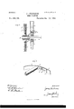
- Figure l is a side elevation.
- Fig. 2 is a top plan view thereof.
- Fig. 3 is a sectional View on the plane indicated by the dotted line x, x, of Fig. 2, and:
- Fig. 4 is a perspective view of a portion of the tire of the preferred form of my ground wheel.
- A designates the frame of the machine which is mounted on the carrying axle B, the ends of which are provided with the usual spindles Z9, the axles within such spindles being made polygonal as at b.' On the spindles of the axle are fitted the ground wheels C, C, which sustain the machine, and on the front part of the frame A, is arranged the depending plow stock or stocks D, carrying the furrow opening shovel d.
- Each ground Wheel has the inner end of its hub provided with serrations or teeth e, and with the toothed hub is adapted to engage a slidable collar E, that is itted and guided on the polygonal part b', of the axle, whereby the wheel can rotate loosely on the axle or be rigidly connected thereto according as the collar E, is adjusted Serial No. 425.506. (No model.)
- This adjustment of the slidable collar E may be eli'ected by a sliding rodf, which is guided in a suitable guide or bearing f', on the main frame, and the outer end of this rod has an angular arm f2, which lits in an angular groove f3, in the collar, while the other end of the rod has an operating handle or lever F, which can be easily grasped and moved by the driver occupying the seat G, mounted on a spring support g, attached to the rear part of the main frame.
- the ground wheels C, C, of the machine may be the ordinary flat or concave form of Wheels, used in this class of machines, but I prefer to employ thenovel construction of expansible wheel shown in the drawings, which can be adjusted to plant the corn in the hills at different distances apart.
- my improved ground wheel I employ a solid hub h, an expansible felly c', i', and radially adjustable sectional spokes j, j', intermediate between the hub and felly.
- the felly consists of aseries of segments z', i', cach of which has one end depressed as at t2, beyond or Within the plane of its tread, and forming an abrupt shoulder i3, and this depressed end of the felly section 2, receives the end of the adjacent section i', whereby the contiguous ends of the felly sections are lapped, and the end of the section c", abuis against the shoulder i3, of the section c', and the tread of the wheel is substantially continuous.
- the lapped ends of the felly-sections are slotted longitudinally at It, the slots being coincident, and through the slots of the lapped ends passes a bolt k, to adjustably connect the telly sections together.
- the outer section j, of the spoke one of which is provided for each section of the felly, is rigidly secured in any suitable manner to its felly section i, or z", at a point at one side of the abrupt shoulder 3, of said felly section, and the inner end of the solid spoke section j, is fitted in the hollow inner spoke section j', said sections j, j', of the spoke being held adj ustably together by means of a set screw Z, which Works in a threaded opening in the' tubular spoke section j', and bears against the solid spoke sectionj, as indicated at Fig. l.
- the diameter of the IOO ground wheel is increased by expanding the telly sections and the spokes; but to plant the corn closer together, the wheel is contracted in the manner explained.
- M. N are the feeding disks which are carried by the axle B, ot the machine; and in the periphery ot each disk is provided a series ot radial cups m, which are adapted to convey the grain trom the hopper and deposit the same into the tube O.
- the intervals between the hills can also be regulated by spacing the cups at different distances in the periphery ot the feeding wheel.
- the feeding wheel operates in a convex recess in the lower side ot a support or block I), which is rigid with the main trame A, and through this support passes the lower open part ot the hopper Q, in which the feeding wheel operates, said hopper having a regulating cut-ott p, and being suitably held on the main trame.
- a caster wheel R journaled in the lower end ot a vertically adjustable hanger R', which is linked at a', to a rock shatt s, journaled on the main traine and operated by a lever S.
- the machine is drawn by a tongue (not shown) which is suitably connected to the main frame.
- the expansible ground wheel comprising a hub, the extensible spokes, and the sectional telly t, t', each section having one end thereof depressed below or within the plane ot its tread, forming an abrupt shoulder, and the adjacent section having its end fitted in said depressed portion, and means tor clamping the telly sections, rigidly together, substantially as described.
- the expansible ground wheel comprising the hub, the sectional telly in which each section has the slotted end i2, depressed within the plane ot the tread thereof, and forming an abrupt shoulder t3, and the adjacent section iitted in said depression 2, the bolts passing through slots in the lapped ends ot the telly sections, and the extensible spokes, each having one end secured to the telly section and its other end secured to the hub, the meeting ends ot the spoke sections being clamped together, substantially as described.
- the expansible ground wheel comprising a hub having its inner end toothed, the extensible spokes and the sectional telly t, t', each section having one end thereof depressed below or within the plane ot its tread, forming an abrupt shoulder, and the adjacent section having its end fitted in said depressed portion,and means tor clamping the telly sections rigidly together, in combination with a polygonal axle extending loosely through the hub ot the wheel, a slidable toothed collar tted on the polygonal axle and adapted to engage the toothed end ot the hub, and a slidable rod guided on the main trame and connected to the slidable collar, substantially as and tor the purpose set forth.
Landscapes
- Life Sciences & Earth Sciences (AREA)
- Soil Sciences (AREA)
- Environmental Sciences (AREA)
- Cultivation Receptacles Or Flower-Pots, Or Pots For Seedlings (AREA)
Description
(No Model.) 2 Sheets-Sheet 1.
J. ANDERSON. CORN PLANTBR.
No. 489,446 Patented Jen. 10,1893.
ixumumi l.. i J We?. A
@nda/wm www I Tn: nous s 21ans co N. n.c
(No Model.) 2 sheets-sheet 2.
J. ANDERSON;
CORN PLANTBR. No. 489,446. Patented Jan. 10, 1893.
j 'P v QP f e 2 2? i .Jkt P f2 Wfz/zesss'.'
UNITED STATES PATENT @EET-CE.
JAMES ANDERSON, OF I-IABRODSBURG, KENTUCKY.
CORN-PLANTER.
SPECIFICATION forming part of Letters Patent No. 489,446, dated January I0, 1893.
Application filed March 18, 1892.
To @ZZ whom it may concern'.-
Be it known that I, JAMES ANDERSON, a citizen of the United States, residing at Harrodsburg, in the county of Mercer and State of Kentucky, have invented certain new and useful Improvements in Corn-Planters; and I do declare the following to be a full, clear, and exact description of the invention, such as will enable others skilled in the art to which it appertains to make and use the same.
My presentinvention relates to improvements in corn planters, and the objects, are, rst, to provide means for automatically planting the corn in hills at variable distances apart, secondly, to control the planting mechanism and easily throw the same into and out of use; and finally to simplify the construction and cheapen the manufacture of the machine. v
With these ends in view the invention consists in the combination and construction of parts which will be hereinafter fully described and claimed. l
The invention is fully illustrated in the accompanying drawings, forming a part thereof, and in which:
Figure l, is a side elevation. Fig. 2, is a top plan view thereof. Fig. 3, is a sectional View on the plane indicated by the dotted line x, x, of Fig. 2, and: Fig. 4, is a perspective view of a portion of the tire of the preferred form of my ground wheel.
Like letters of reference denote corresponding parts in the several figures of the drawings, referring to which:
A, designates the frame of the machine which is mounted on the carrying axle B, the ends of which are provided with the usual spindles Z9, the axles within such spindles being made polygonal as at b.' On the spindles of the axle are fitted the ground wheels C, C, which sustain the machine, and on the front part of the frame A, is arranged the depending plow stock or stocks D, carrying the furrow opening shovel d. Each ground Wheel has the inner end of its hub provided with serrations or teeth e, and with the toothed hub is adapted to engage a slidable collar E, that is itted and guided on the polygonal part b', of the axle, whereby the wheel can rotate loosely on the axle or be rigidly connected thereto according as the collar E, is adjusted Serial No. 425.506. (No model.)
out or in engagement with the wheel. This adjustment of the slidable collar E, may be eli'ected by a sliding rodf, which is guided in a suitable guide or bearing f', on the main frame, and the outer end of this rod has an angular arm f2, which lits in an angular groove f3, in the collar, while the other end of the rod has an operating handle or lever F, which can be easily grasped and moved by the driver occupying the seat G, mounted on a spring support g, attached to the rear part of the main frame.
The ground wheels C, C, of the machine may be the ordinary flat or concave form of Wheels, used in this class of machines, but I prefer to employ thenovel construction of expansible wheel shown in the drawings, which can be adjusted to plant the corn in the hills at different distances apart.
ln my improved ground wheel I employ a solid hub h, an expansible felly c', i', and radially adjustable sectional spokes j, j', intermediate between the hub and felly. The felly consists of aseries of segments z', i', cach of which has one end depressed as at t2, beyond or Within the plane of its tread, and forming an abrupt shoulder i3, and this depressed end of the felly section 2, receives the end of the adjacent section i', whereby the contiguous ends of the felly sections are lapped, and the end of the section c", abuis against the shoulder i3, of the section c', and the tread of the wheel is substantially continuous. The lapped ends of the felly-sections are slotted longitudinally at It, the slots being coincident, and through the slots of the lapped ends passes a bolt k, to adjustably connect the telly sections together. The outer section j, of the spoke, one of which is provided for each section of the felly, is rigidly secured in any suitable manner to its felly section i, or z", at a point at one side of the abrupt shoulder 3, of said felly section, and the inner end of the solid spoke section j, is fitted in the hollow inner spoke section j', said sections j, j', of the spoke being held adj ustably together by means of a set screw Z, which Works in a threaded opening in the' tubular spoke section j', and bears against the solid spoke sectionj, as indicated at Fig. l.
When it is desired to plant the corn at further intervals apart, the diameter of the IOO ground wheel is increased by expanding the telly sections and the spokes; but to plant the corn closer together, the wheel is contracted in the manner explained.
M. N, are the feeding disks which are carried by the axle B, ot the machine; and in the periphery ot each disk is provided a series ot radial cups m, which are adapted to convey the grain trom the hopper and deposit the same into the tube O. The intervals between the hills can also be regulated by spacing the cups at different distances in the periphery ot the feeding wheel. The feeding wheel operates in a convex recess in the lower side ot a support or block I), which is rigid with the main trame A, and through this support passes the lower open part ot the hopper Q, in which the feeding wheel operates, said hopper having a regulating cut-ott p, and being suitably held on the main trame.
At the rear ot the machine is a caster wheel R, journaled in the lower end ot a vertically adjustable hanger R', which is linked at a', to a rock shatt s, journaled on the main traine and operated by a lever S.
The machine is drawn by a tongue (not shown) which is suitably connected to the main frame.
The operation ot my invention will be readily understood trom the foregoing description taken in connection with the drawings.
Having described my invention what I claim is:
l. In a corn planter the expansible ground wheel comprising a hub, the extensible spokes, and the sectional telly t, t', each section having one end thereof depressed below or within the plane ot its tread, forming an abrupt shoulder, and the adjacent section having its end fitted in said depressed portion, and means tor clamping the telly sections, rigidly together, substantially as described.
2. In a corn planter the expansible ground wheel comprising the hub, the sectional telly in which each section has the slotted end i2, depressed within the plane ot the tread thereof, and forming an abrupt shoulder t3, and the adjacent section iitted in said depression 2, the bolts passing through slots in the lapped ends ot the telly sections, and the extensible spokes, each having one end secured to the telly section and its other end secured to the hub, the meeting ends ot the spoke sections being clamped together, substantially as described.
3. In a corn planter the combination with a main trame, an axle, ot polygonal form in cross section, the rigid support on the main trame having the convex lower side, the feeding wheel carried by the axle and operating in said convex side ot the support, and the hopper mounted on the support and extending through the same; ot the expansible ground wheel loosely mounted on the axle and comprising the hub having its inner end serrated or toothed, the extensible spokes and the sectional telly to which the spokes are secured, a slidable toothed collar fitted on the polygonal axle, and a slidable rod guided on the main traine and connected to the slidable collar, substantially as and tor the purpose set forth.
Lt. In a corn planter, the expansible ground wheel comprisinga hub having its inner end toothed, the extensible spokes and the sectional telly t, t', each section having one end thereof depressed below or within the plane ot its tread, forming an abrupt shoulder, and the adjacent section having its end fitted in said depressed portion,and means tor clamping the telly sections rigidly together, in combination with a polygonal axle extending loosely through the hub ot the wheel, a slidable toothed collar tted on the polygonal axle and adapted to engage the toothed end ot the hub, and a slidable rod guided on the main trame and connected to the slidable collar, substantially as and tor the purpose set forth.
In testimony whereof I aiix my signature in presence ot two witnesses.
JAMES ANDERSON.
Witnesses:
L. P. HARRIS, Il. T. YOUNG.
Publications (1)
| Publication Number | Publication Date |
|---|---|
| US489446A true US489446A (en) | 1893-01-10 |
Family
ID=2558292
Family Applications (1)
| Application Number | Title | Priority Date | Filing Date |
|---|---|---|---|
| US489446D Expired - Lifetime US489446A (en) | Corn-planter |
Country Status (1)
| Country | Link |
|---|---|
| US (1) | US489446A (en) |
Cited By (3)
| Publication number | Priority date | Publication date | Assignee | Title |
|---|---|---|---|---|
| US2528996A (en) * | 1947-06-13 | 1950-11-07 | James L Binkley | Corn planter |
| US3802743A (en) * | 1972-04-17 | 1974-04-09 | Spector G | Variable diameter wheel |
| US4023511A (en) * | 1975-11-10 | 1977-05-17 | Newman Dwight C | Seed planting roller device |
-
0
- US US489446D patent/US489446A/en not_active Expired - Lifetime
Cited By (3)
| Publication number | Priority date | Publication date | Assignee | Title |
|---|---|---|---|---|
| US2528996A (en) * | 1947-06-13 | 1950-11-07 | James L Binkley | Corn planter |
| US3802743A (en) * | 1972-04-17 | 1974-04-09 | Spector G | Variable diameter wheel |
| US4023511A (en) * | 1975-11-10 | 1977-05-17 | Newman Dwight C | Seed planting roller device |
Similar Documents
| Publication | Publication Date | Title |
|---|---|---|
| US6983705B1 (en) | Depth control mechanism | |
| US447938A (en) | Covering-wheel for drills | |
| US601342A (en) | priberg- | |
| US272291A (en) | Corn-planter | |
| US352923A (en) | Corn-planter | |
| US491390A (en) | Trotter | |
| US59283A (en) | Improvement in seeding-machines | |
| US426448A (en) | Check-row corn-planter | |
| US408283A (en) | Stalk-cutter wheel for sulky-plows | |
| US499844A (en) | Disk cultivator | |
| US90640A (en) | Improvement in corn-planters | |
| US638850A (en) | Corn-planter. | |
| US104303A (en) | Improved corn-planter | |
| US840020A (en) | Grain-drill. | |
| US328561A (en) | Land-marker | |
| US42612A (en) | Improved corn-planter | |
| US335361A (en) | Check-rower for corn-planters | |
| US108468A (en) | Improvement in corn-planters | |
| US492243A (en) | Potato cutter and planter | |
| US87721A (en) | Improvement in revolving cultivator | |
| US787467A (en) | Seeder. | |
| US607887A (en) | Marker for seed or corn planters | |
| US969338A (en) | Seed-planter. | |
| US309004A (en) | stewart | |
| US412907A (en) | Seed-planter |