US488631A - Fracture apparatus - Google Patents
Fracture apparatus Download PDFInfo
- Publication number
- US488631A US488631A US488631DA US488631A US 488631 A US488631 A US 488631A US 488631D A US488631D A US 488631DA US 488631 A US488631 A US 488631A
- Authority
- US
- United States
- Prior art keywords
- piece
- frame
- extension
- standard
- limb
- Prior art date
- Legal status (The legal status is an assumption and is not a legal conclusion. Google has not performed a legal analysis and makes no representation as to the accuracy of the status listed.)
- Expired - Lifetime
Links
- 206010017076 Fracture Diseases 0.000 description 16
- 210000003414 extremity Anatomy 0.000 description 16
- 210000002683 foot Anatomy 0.000 description 7
- 210000003813 thumb Anatomy 0.000 description 7
- 210000003127 knee Anatomy 0.000 description 5
- 210000002105 tongue Anatomy 0.000 description 3
- PXHVJJICTQNCMI-UHFFFAOYSA-N Nickel Chemical compound [Ni] PXHVJJICTQNCMI-UHFFFAOYSA-N 0.000 description 2
- 239000004744 fabric Substances 0.000 description 2
- 239000010985 leather Substances 0.000 description 2
- 210000002414 leg Anatomy 0.000 description 2
- 229910052751 metal Inorganic materials 0.000 description 2
- 239000002184 metal Substances 0.000 description 2
- 229910000831 Steel Inorganic materials 0.000 description 1
- 229910052782 aluminium Inorganic materials 0.000 description 1
- XAGFODPZIPBFFR-UHFFFAOYSA-N aluminium Chemical compound [Al] XAGFODPZIPBFFR-UHFFFAOYSA-N 0.000 description 1
- 210000003423 ankle Anatomy 0.000 description 1
- 230000000994 depressogenic effect Effects 0.000 description 1
- 239000013013 elastic material Substances 0.000 description 1
- 210000000245 forearm Anatomy 0.000 description 1
- 210000000629 knee joint Anatomy 0.000 description 1
- 229910052759 nickel Inorganic materials 0.000 description 1
- 239000011505 plaster Substances 0.000 description 1
- 230000001105 regulatory effect Effects 0.000 description 1
- 230000013707 sensory perception of sound Effects 0.000 description 1
- 239000010959 steel Substances 0.000 description 1
- 210000000689 upper leg Anatomy 0.000 description 1
Images



Classifications
-
- A—HUMAN NECESSITIES
- A61—MEDICAL OR VETERINARY SCIENCE; HYGIENE
- A61G—TRANSPORT, PERSONAL CONVEYANCES, OR ACCOMMODATION SPECIALLY ADAPTED FOR PATIENTS OR DISABLED PERSONS; OPERATING TABLES OR CHAIRS; CHAIRS FOR DENTISTRY; FUNERAL DEVICES
- A61G13/00—Operating tables; Auxiliary appliances therefor
- A61G13/0036—Orthopaedic operating tables
Definitions
- My invention is designed to obviate this difficulty by providing a portable apparatus by means of which the operator, without the aid of an assistant, can apply and maintain proper extension and counter-extension of,
- Theinvention consists essentially of a frame work composed of a horizontal base frame with two attached end uprights or standards. one of which is angularly adjustablefrom one to the other of which is drawn a band of canvas or other suitable elastic fabric for the fractured limb to rest upon, and which have suitable devices for securing extension and counter-extension of the limb, all of which will be hereinafter set forth.
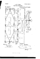
- Figure 1 is an end elevation of the foot standard.
- Fig. 2 is an inside elevation of the head standard.
- Fig. 3 is a plan of the instrument folded up, for transportation.
- Fig. 4 is a plan of foot standard, with Worm screw, and its frame in section.
- Fig. 5 shows side elevation of outer frame of foot standard.
- Fig. 6 shows side elevation of side bar of lower section of head standard.
- Fig. 7 shows side elevation of center bar of lower section of head standard.
- Fig. 8 is plan of base frame.
- Fig. 9 is side elevation of instrument folded up.
- Fig. 10 is plan of clamp device.
- Fig. 11 is side elevation of instrument, extended for fracture at or abovethe knee.
- Fig. 12 side elevation of instrument shortened to its minimum extension.
- Fig. 13 perspective View of instrument adjusted for fracture below knee.
- Fig. lat is side elevation of case.
- Fig. 15 is plan of clamp device.
- Fig. 16 is outside elevation of clamp device,
- the base frame A is composed of the two side bars A, connected at each end by the rods A and A and at the foot end by an end bar or brace A and at its center by the crossbar A and is braced inside by the braces A, which are fastened to the side bars A at a, by rivets, and which have holes in their ends a, through which the end bars A and A pass.
- the head standard B is formed of two sections.
- the lower section is composed of the side bars B, and center bar 13 working on the rod A said side bars B being disk shaped at lower end, corresponding to the disk-shaped ends of the side bars A.
- In each of these disks is a hole, m, which corresponds in certain position of the head standard B with like holes, 0, 0, in the disks of the side bars A, and into which play the tongues of the spring pawls b, which are riveted on the inside of the side bars B, thus locking the joint.
- the side bars B and center bar B are slotted in their upper ends at b.
- the upper section of the head standard B is made of the main piece 0, forming the sides and top,the top being depressed into a curved rest C, which is upholstered; thebraces O and the cross rod 0
- the cross rod C passes through the slots b in the bars B and B and has a thread cut on one projecting end, on which plays the thumb screw 0 against the washer c, the other end having an immovable thumb piece c".
- On this rod 0 are two free cylinders c the ends of which offer shoulders against the sides 0 and the braces O when the thumb screw is tightened.
- Riveted on the lower ends of the piece O, about one inch above the cross rod 0 are the clamps or keepers c which receive along the outside surfaces of the piece 0 the upper ends of the side bars B, as shown in Fig. 13, or which act as shoulders, to prevent lateral tipping, as shown in Fig. 11. These keepers are wider toward the base frame, to secure the vertical position of the upper section, as seen in Fig. 11.
- the clamping device D composed of the supporting piece D, riveted at each end to the said braces (3 the back piece D having a threaded hole 61 atits center, in which plays the threaded thumb screw D which passes through the hole 01 in the piece D, and has a shoulder on each side of this piece D; and the clamping bar D, the ends of which pass through the holes 01 in the piece D and are riveted into the back piece D
- the foot standard E is composed of one piece E, forming the tops and sides, the cross bar E and the two rods E fixed in the top piece E and the cross bar E Upon these rods E works, vertically, the sliding frame F,
- the frame F is held together by the nuts 19 screwed upon the threaded ends of the cylinders F
- a small thumb screwe, in the base of the cylinder F bears against the rod E and is used to hold the frame F in any desired position.
- the lower ends of the frame piece E are slotted at q, and work, in these slots, on the rod A Pivoted, at its center, to the center of the cross bar A is the supporting strip R, which is about one foot longer than the cross bar A
- the cross bar A is fixed to the side bars A, just the thickness of the strip R, above their lower edges, and the side bars A each have a .broad notch, .9, into which the stripR springs,
- Buttoned on the wheel shaft G is a broad strip of leather T carrying the rectangular metal loop t.
- the slidingframe F is then adjusted perpendicularly so that the webbing will be level.
- the worm screw N is then turned, until the webbing is stretched to the desired tension.
- a slit is cut in the webbing to receive the heel of the patient.
- the instrument is then placed so that the knee joint rests upon the rest 0', and the fractured limb upon the webbing.
- a clove-hitch is taken around the ankle with a strip of strong cloth WV, the free ends being tied to the metal loop 25.
- the worm screw M is then turned until the fractured limb is extended to the desired length, the brace or rest 0, by its pressure against the leg above the knee, providing the necessary counter-extension.
- the bandages are then applied, inclosing with the limb, the
- the rest O In fractures of the arm, the rest O, is placed in the arm-pit to secure the necessary counter-extension. If the fracture is above the knee'(see Fig. 11), or for any reason a longer distance is desired between the tension shaft G and the counter-extension brace or rest 0, the head standard B is ad: justed by pressing the handles of the pawls b and withdrawing the ratchet tongues from the holes 0, in the disks of the side bars A, and then tilting the standard outward, till the pawl tongues catch in the next set of holes 0'.
- the upper section of the head standard is drawn out until the side bars B, are free from the keepers 0 it is then brought to a vertical position, and moved toward the base frame, the rod 0 sliding in the slots 19' and the keepers c forming ashoulderagainst the upper edge of the bars B.
- the distance between the standards can be further regulated, to extent of the length of the slots 19, and the desired position secured by tightening the thumb screw 0.
- the webbing S is arranged, and the sliding frame F adjusted to the altered height of the rest 0.
- the injured limb is placed upon the supporting band and the extension applied to the foot as above described, and in case of aleg, counter-exten sion is secured by the resistance of the brace 0, against the upper part of the thigh of the patient.
- the advantages of the instrument are especially marked in using plaster bandages; a piece of clean wadding being first laid upon the webbing, is folded about the fractured limb, and the inclosing of the webbing within the bandages materially strengthens the splint.
- the instrument is preferably made of aluminum or nickel plated steel, is very conven- IIO ient and portable, being readily placed, and easily carried in a canvas or leather case, Fig. 14.
- An apparatus for the treatment of fractures containing a horizontal base frame; two adjustable standards attached to the ends of said frame; a broad band stretched from one to the other standard; devices for adjusting said band; devices for applying extension and counter-extension to the fractured limb, and devices for holding the standards in adjusted position; all arranged and operated substantially as herein shown and described. 7
Landscapes
- Health & Medical Sciences (AREA)
- Orthopedic Medicine & Surgery (AREA)
- Engineering & Computer Science (AREA)
- Biomedical Technology (AREA)
- Life Sciences & Earth Sciences (AREA)
- Animal Behavior & Ethology (AREA)
- General Health & Medical Sciences (AREA)
- Public Health (AREA)
- Veterinary Medicine (AREA)
- Orthopedics, Nursing, And Contraception (AREA)
Description
Sheets-Sheet 2.
(No Model.)
G. W. KING. FRAGTURE APPARATUS. No. 488,681 Patented Dec. 27,1892. F 4 j;
---; E- v4 0 X 6)) 4 B1 B1 1 728. 177.9. 109x14 Wham J Invenlor EMWQESKL/i (No Model.) 4 Sheets-Sheet 3.
G. W. KING.
PRAGTURE APPARATUS. N0. 488,631. Patented Dec. 27', 1892.
Vii/7208a.
My M44757, Invenloz:
(No Model.) 4 Sneets -sneet 4.
G. W. KING.. FRAOTURE APPARATUS.
I No. 488,631.. Patented Dec. 27, 1892..
mine 88 es. [r2 VFJZZOJ.
f/ i u, him/K liar/z y.
NITED STATES P TENT OFFICE.
GEORGE WEIRS KING, OF HELENA, MONTANA.
FRACTURE APPARATUS.
SPECIFICATION forming'part of Letters Patent No. 488,631, dated December 27, 1892.
Application filed February 23, 1892. Serial No. 422,576. (No model.)
frequent moving of the injured limb during the application of splints or bandages.
My invention is designed to obviate this difficulty by providing a portable apparatus by means of which the operator, without the aid of an assistant, can apply and maintain proper extension and counter-extension of,
and support for, the broken limb, and, at the same time have free access to every part of it for the convenient application of the splints or bandages.
Theinvention consists essentially of a frame work composed of a horizontal base frame with two attached end uprights or standards. one of which is angularly adjustablefrom one to the other of which is drawn a band of canvas or other suitable elastic fabric for the fractured limb to rest upon, and which have suitable devices for securing extension and counter-extension of the limb, all of which will be hereinafter set forth.
Figure 1 is an end elevation of the foot standard. Fig. 2 is an inside elevation of the head standard. Fig. 3 is a plan of the instrument folded up, for transportation. Fig. 4 is a plan of foot standard, with Worm screw, and its frame in section. Fig. 5 shows side elevation of outer frame of foot standard. Fig. 6 shows side elevation of side bar of lower section of head standard. Fig. 7 shows side elevation of center bar of lower section of head standard. Fig. 8 is plan of base frame. Fig. 9 is side elevation of instrument folded up. Fig. 10 is plan of clamp device. Fig. 11 is side elevation of instrument, extended for fracture at or abovethe knee. Fig. 12 side elevation of instrument shortened to its minimum extension. Fig. 13 perspective View of instrument adjusted for fracture below knee. Fig. lat is side elevation of case. Fig. 15 is plan of clamp device. Fig. 16 is outside elevation of clamp device, holding webbing.
Similar letters of reference refer to similar parts throughout the drawings.
The base frame A is composed of the two side bars A, connected at each end by the rods A and A and at the foot end by an end bar or brace A and at its center by the crossbar A and is braced inside by the braces A, which are fastened to the side bars A at a, by rivets, and which have holes in their ends a, through which the end bars A and A pass.
The head standard B is formed of two sections. The lower section is composed of the side bars B, and center bar 13 working on the rod A said side bars B being disk shaped at lower end, corresponding to the disk-shaped ends of the side bars A. In each of these disks is a hole, m, which corresponds in certain position of the head standard B with like holes, 0, 0, in the disks of the side bars A, and into which play the tongues of the spring pawls b, which are riveted on the inside of the side bars B, thus locking the joint. The side bars B and center bar B are slotted in their upper ends at b.
The upper section of the head standard B is made of the main piece 0, forming the sides and top,the top being depressed into a curved rest C, which is upholstered; thebraces O and the cross rod 0 The cross rod C passes through the slots b in the bars B and B and has a thread cut on one projecting end, on which plays the thumb screw 0 against the washer c, the other end having an immovable thumb piece c". On this rod 0 are two free cylinders c the ends of which offer shoulders against the sides 0 and the braces O when the thumb screw is tightened. v
Riveted on the lower ends of the piece O, about one inch above the cross rod 0 are the clamps or keepers c which receive along the outside surfaces of the piece 0 the upper ends of the side bars B, as shown in Fig. 13, or which act as shoulders, to prevent lateral tipping, as shown in Fig. 11. These keepers are wider toward the base frame, to secure the vertical position of the upper section, as seen in Fig. 11.
Fasten ed to the upper surfaces of the braces C is-the clamping device D, composed of the supporting piece D, riveted at each end to the said braces (3 the back piece D having a threaded hole 61 atits center, in which plays the threaded thumb screw D which passes through the hole 01 in the piece D, and has a shoulder on each side of this piece D; and the clamping bar D, the ends of which pass through the holes 01 in the piece D and are riveted into the back piece D The foot standard E is composed of one piece E, forming the tops and sides, the cross bar E and the two rods E fixed in the top piece E and the cross bar E Upon these rods E works, vertically, the sliding frame F,
composed of the cross pieces F, the cylinders F and the uprightsf, g, h, andt'. Supported in hearings in the uprightsf, g and his the wheel shaft G, carrying the fixed wheel G between the uprights fand g and furnished with the buttonsj. The wheel shaft H, carrying the fixed wheel H and the hooks K, is supported in bearings in the uprights g, h and z. Riveted to the uprightfis the frame L, see Fig. 4, carrying the worm screw M, which works into the wheel G and turns the shaft G. A similar frame fitted on the upright t, carries the worm screw N,which turns the wheel H, and thus the shaft H. The frame F is held together by the nuts 19 screwed upon the threaded ends of the cylinders F A small thumb screwe, in the base of the cylinder F bears against the rod E and is used to hold the frame F in any desired position. The lower ends of the frame piece E are slotted at q, and work, in these slots, on the rod A Pivoted, at its center, to the center of the cross bar A is the supporting strip R, which is about one foot longer than the cross bar A The cross bar A is fixed to the side bars A, just the thickness of the strip R, above their lower edges, and the side bars A each have a .broad notch, .9, into which the stripR springs,
when swung out at right angles to the base frame.
Buttoned on the wheel shaft G, is a broad strip of leather T carrying the rectangular metal loop t.
Having thus described my invention, its modeof operation is as followsz-Taking it, folded, from the case X, as seen in Figs. 3 and 9, and supposing the case to be treated is a fracture below the knee (see Fig. 13), or of the forearm, the head standard B is brought to a vertical position, in which it is locked by the pawl 19 at its joint with the base frame A. The upper section is adjusted in a vertical position in line with the lower section, and pressed downward, the cross rod C working down in the slots 1), and the keepers c embracing the upper ends of the side bars B. (This is also the adjustment of these two sections, as to each other, when the head standard is folded down.) Next the foot standard E is raised to a vertical position and being pressed downward, drops, the length of the slots q, into position on the rod A The supporting strip. R is swung to a position at right angles to the long way of the frame, directly under the cross bar A, and is held in position by the notches s. A piece of strong webbing or other suitable elastic material S, is fastened at one end to the hooks K on the shaft H; the other end is carried to the head standard B, and is passed over the upholstered rest 0 andbetween the clamp D and the piece D, where it is tightly held by turning the thumb screw D until the clamp D presses it against the supporting piece D. The slidingframe F is then adjusted perpendicularly so that the webbing will be level. The worm screw N is then turned, until the webbing is stretched to the desired tension. In fractures of the leg, a slit is cut in the webbing to receive the heel of the patient. The instrument is then placed so that the knee joint rests upon the rest 0', and the fractured limb upon the webbing. A clove-hitch is taken around the ankle with a strip of strong cloth WV, the free ends being tied to the metal loop 25. The worm screw M is then turned until the fractured limb is extended to the desired length, the brace or rest 0, by its pressure against the leg above the knee, providing the necessary counter-extension. The bandages are then applied, inclosing with the limb, the
webbing S. In fractures of the arm, the rest O, is placed in the arm-pit to secure the necessary counter-extension. If the fracture is above the knee'(see Fig. 11), or for any reason a longer distance is desired between the tension shaft G and the counter-extension brace or rest 0, the head standard B is ad: justed by pressing the handles of the pawls b and withdrawing the ratchet tongues from the holes 0, in the disks of the side bars A, and then tilting the standard outward, till the pawl tongues catch in the next set of holes 0'. The upper section of the head standard is drawn out until the side bars B, are free from the keepers 0 it is then brought to a vertical position, and moved toward the base frame, the rod 0 sliding in the slots 19' and the keepers c forming ashoulderagainst the upper edge of the bars B. The distance between the standards can be further regulated, to extent of the length of the slots 19, and the desired position secured by tightening the thumb screw 0. The webbing S is arranged, and the sliding frame F adjusted to the altered height of the rest 0. The injured limb is placed upon the supporting band and the extension applied to the foot as above described, and in case of aleg, counter-exten sion is secured by the resistance of the brace 0, against the upper part of the thigh of the patient.
The advantages of the instrument are especially marked in using plaster bandages; a piece of clean wadding being first laid upon the webbing, is folded about the fractured limb, and the inclosing of the webbing within the bandages materially strengthens the splint.
The instrument is preferably made of aluminum or nickel plated steel, is very conven- IIO ient and portable, being readily placed, and easily carried in a canvas or leather case, Fig. 14.
Having thus described my invention, I claim as new and desire to secure by Letters Patent;
1. An apparatus for the treatment of fractures containing a horizontal base frame; two adjustable standards attached to the ends of said frame; a broad band stretched from one to the other standard; devices for adjusting said band; devices for applying extension and counter-extension to the fractured limb, and devices for holding the standards in adjusted position; all arranged and operated substantially as herein shown and described. 7
2. In. an apparatus designed for the treatment of fractures, the combination with abase frame and two opposite uprights or standards fixed at the ends of the base frame of a band adapted to support the fractured limb, and stretched adj ustably between said standards, substantially as herein shown and described.
3. In an apparatus for treating fractures the combination of a base frame with two upright adjustable standards fixed at the ends of the base frame, one provided with a mechanical device for securing extension of the fractured limb, and the other offering a firm brace or rest for the limb above the fracture to secure counter-extension and being adj ustable at any angle from the perpendicular, substantially as herein shown.
4. In an apparatus for treating fractures,
the combination of a band, stretched adjustably between two end standards, supporting the fractured limb in mid-air, with a mechani-' cal device for securing extension of the limb and a firm brace or rest for the limb above the fracture to secure counter-extension, substantially as herein shown.
5. In an apparatus for treating fractures, the combination with a base board or base frame, of end standards, one of which is adjustable at any angle from the perpendicular, as and for the purpose herein described.
6. In an apparatus for treating fractures, the combination, with a base frame, of a standard, having an adjustable sliding frame, carrying two wheel shafts, operated by worm screws, substantially as, and for the purpose, described.
7. In an apparatus for treating fractures,
the combination with a base frame, of an end standard, adapted to use as a brace and rest, jointed to the base frame, and jointed in themiddle so as to be adjustable at any angle from the perpendicular, substantially as shown and described.
In testimony that I claim the foregoing as my invention I have signed my name, in presence of two witnesses, this 13th day of February, 1892.
GEORGE WEIRS KING.
Witnesses:
A. J. STEELE, HENRY W. FOOTE.
Publications (1)
| Publication Number | Publication Date |
|---|---|
| US488631A true US488631A (en) | 1892-12-27 |
Family
ID=2557477
Family Applications (1)
| Application Number | Title | Priority Date | Filing Date |
|---|---|---|---|
| US488631D Expired - Lifetime US488631A (en) | Fracture apparatus |
Country Status (1)
| Country | Link |
|---|---|
| US (1) | US488631A (en) |
Cited By (1)
| Publication number | Priority date | Publication date | Assignee | Title |
|---|---|---|---|---|
| US5025802A (en) * | 1990-02-08 | 1991-06-25 | Lincoln Mills, Inc. | Surgical holding apparatus for distracting ankle |
-
0
- US US488631D patent/US488631A/en not_active Expired - Lifetime
Cited By (1)
| Publication number | Priority date | Publication date | Assignee | Title |
|---|---|---|---|---|
| US5025802A (en) * | 1990-02-08 | 1991-06-25 | Lincoln Mills, Inc. | Surgical holding apparatus for distracting ankle |
Similar Documents
| Publication | Publication Date | Title |
|---|---|---|
| US3528413A (en) | Limb support | |
| US5027799A (en) | Limb supporting device for arthroscopic surgery | |
| US37156A (en) | Improvement in tourniquets | |
| US3753557A (en) | Support for leg during knee surgery | |
| US7156820B2 (en) | Extremity support rack | |
| US1242688A (en) | Extension-splint. | |
| US3981492A (en) | X-ray table patient transfer device or the like with body holding device | |
| US3413971A (en) | Body traction device | |
| US649237A (en) | Fracture apparatus. | |
| US21872A (en) | Extension-splint | |
| US158894A (en) | Improvement | |
| US1530719A (en) | Chiropractic table | |
| US1070467A (en) | Traction-frame. | |
| US661812A (en) | Surgical appliance. | |
| US2604889A (en) | Traction splint | |
| US12944A (en) | Istvalib-bedstead | |
| US2829640A (en) | Surgical leg holders | |
| US891679A (en) | Operating-table. | |
| US921559A (en) | Osteopathic table. | |
| US776335A (en) | Vertebral stretcher. | |
| US17195A (en) | Stjkgical splint apparatus | |
| DE2744518A1 (en) | Inflatable flexible support pad for raised arm - has sheet of material with straps for clamping arm | |
| US402095A (en) | Fifths to frank p | |
| US2244758A (en) | Orthopedic table | |
| US432888A (en) | Fracture apparatus |