US487584A - Motor - Google Patents
Motor Download PDFInfo
- Publication number
- US487584A US487584A US487584DA US487584A US 487584 A US487584 A US 487584A US 487584D A US487584D A US 487584DA US 487584 A US487584 A US 487584A
- Authority
- US
- United States
- Prior art keywords
- valve
- ports
- outlet
- series
- rod
- Prior art date
- Legal status (The legal status is an assumption and is not a legal conclusion. Google has not performed a legal analysis and makes no representation as to the accuracy of the status listed.)
- Expired - Lifetime
Links
- 210000000038 chest Anatomy 0.000 description 20
- 239000003795 chemical substances by application Substances 0.000 description 18
- 210000002832 Shoulder Anatomy 0.000 description 10
- 238000010276 construction Methods 0.000 description 6
- SXYIRMFQILZOAM-HVNFFKDJSA-N (3R,5aS,6R,8aS,9R,10S,12R,12aR)-10-methoxy-3,6,9-trimethyldecahydro-3,12-epoxypyrano[4,3-j][1,2]benzodioxepines Chemical compound C1C[C@H]2[C@H](C)CC[C@H]3[C@@H](C)[C@@H](OC)O[C@H]4[C@]32OO[C@@]1(C)O4 SXYIRMFQILZOAM-HVNFFKDJSA-N 0.000 description 2
- 241000288049 Perdix perdix Species 0.000 description 2
- 238000005192 partition Methods 0.000 description 2
- XLYOFNOQVPJJNP-UHFFFAOYSA-N water Substances O XLYOFNOQVPJJNP-UHFFFAOYSA-N 0.000 description 2
- 230000003245 working Effects 0.000 description 2
Images

Classifications
-
- F—MECHANICAL ENGINEERING; LIGHTING; HEATING; WEAPONS; BLASTING
- F01—MACHINES OR ENGINES IN GENERAL; ENGINE PLANTS IN GENERAL; STEAM ENGINES
- F01L—CYCLICALLY OPERATING VALVES FOR MACHINES OR ENGINES
- F01L23/00—Valves controlled by impact by piston, e.g. in free-piston machines
Definitions
- the invention relates to motors such as shown and described in the application for Letters Patent 'of the United States, Serial No. 399,511, filed-by me July 14-, 1891, and allowed January 4, 1892'.
- the object of the invention is to provide a n'ewa'nd improved motor which is simple-and durable in construction, very effective in operation, and more especially designed for use on Artesian Wells or other devices to obtain, with alow pressureof water as a drivingmedium, a large amount of power for actuating other machinery.
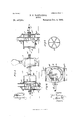
- FIG. 1 is a side elevation of theimprovement.
- Fig. 2 is a sectionalplan view of the same on the line:2 2 of Figs. 1 and 3.
- Fig. 3 is a sectionalplan view of the same on the line:2 2 of Figs. 1 and 3.
- Fig. 4 is atransverse section of the same on the line4 4 of Figs. 2 and 4
- Fig. 5 is a face view of one of the valves.
- the machinery to be actuated by the improved motor may be of any desired construction; but for'thepurposeof illustration the drawings represent a double-acting pump A.
- cylindrical valves G and G are formed with a central hub and radial spokes, so as to make a discharge-opening for the cylinders E and .E at the time said valves are seated over the inlet-ports of the inlet-chambers F and F respectively, and said valves being at all times either entirely surrounded or entirely filled with the motive agent and having outlet-ports or inlet-ports entirely around their Iperimeters at all times are constantly and perfectly balanced.
- the .chests Fand F are somewhat larger in diameter than thevalve-seats F and F so that the incoming motive agent can circulate all around the chest and pass intothe cylinder from all sides at the time the valve is in an outermost position in the respective chest.
- valves G and G are provided with outwardly-extending valve-stems H and H, respectively, passing through suitable stuffingboxes in the heads attached to the chambers F and F stems H and H are pivotally connected with transversely-extending arms I and I, respectively, pivoted at their rear ends to brackets
- the said rod sliding in bearings K and K formed on the arms of K and K, respectively, securedto the power-rod G at opposite sides of the pump A
- the bearings K and *K of the arms K and K, respectively, are adapted to engage col- .lars L and L respectively, formed on the ends of the springs L and L, respectively, preferably made V-shaped, asshown in Fig.
- the free ends of the arms I and I are 2, and carrying on their outer ends collars L and L fitted to slide looselyon the rod J. It is understood that the collars L and L are also fitted to slide loosely on the rod J.
- the collars L and L are adapted to abut against collars N and N, respectively, secured by set-screws or other means to the rod J.
- the collars N and N are adapted to abut against shoulders O and 0 respectively, of springarms 0 add 0, respectively, secured to the chests F and F, respectively, as plainly shown in Fig. 2.
- the spring-arms O and 0 have their free ends 0 and O curved to be readily engaged by lugs P and P, respectively, secured to the arms K and K, respectively, above described.
- valve G When the several parts are in the position as illustrated in the drawings, then the valve G is seated over and closes theinlet ports of the chest F, while the outlet-ports of said chestF are left open to exhaust the cylinder E. Mean while the valve G is seated over and closes the outlet-ports of the chest F, while the inlet-ports of said chest F are left open, sothat the motive agent can pass through the chamber F into the cylinder E, forcing the piston D in the direction of the arrow 0., and thereby moving the power-rod O, the piston B, and the piston D in the same direction, as will be readily understood by reference to Fig. 3.
- this motor is very simple and durable in construction, is completely automatic in operation, and develops considerable power, it being understood that the stroke of the piston B is equal to that of each of the pistons D and D. It will further be seen that the motor is notliable to get out of order, and as the most of the parts are located on the outside of the cylinders and chests they can be readily examined and inspected at all times to insure their proper workings.
- a hollow cylindrical valve-seat In a motor-engine, the combination, with a single-acting piston and cylinder, of a hollow cylindrical valve-seat, a circular series of supply-ports occupying the inner half of said valve-seat and extending entirely around the same, a circular series of exhaust-ports occupying the outer half of said valve-seat and extending entirely around the same, a hollow cylindrical balanced valve adjusted to operate piston-like within said valve-seat and to open and close the aforesaid two see ries of ports alternately, a valve-stem fas tened axially to said valve, a supply-chamber extending entirely around and inclosing said series of supply-ports and provided with supply-pipe connections, an exhaust-chamber extending entirely around and inclosing said Series of exhaust-ports and provided with exhaust-pipe connections, and a circular head bolted to said exhaust-chamber so as to close the outer end of said valve-seat and provided with a stutfing-box
- valve-chest provided with a hollow cylindrical valve-seat having a series of inletports around its inner l1alf,a series of outletports around its outer hall, an inlet-chamber inclosing said inlet-ports and provided with a supplypipe and connections, an outletchamber inclosing said outlet-ports and provided with a discharge-pipe and connections, and a hollow cylindrical balanced valve provided with an axial stem and adjusted to slide in said valve-seat, substantially as shown and described.
- valvechest comprising a hollow cylindrical valveseat having a series of inlet-ports around its inner half and a series of outlet-ports around its outer half, an inlet-chamber inclosing said series of inlet-ports and provided with a supply-pipe and connections, an outlet-chamber inclosing said series of outlet-ports and provided with an exhaust-pipe and connections, and a head bolted to said outlet-chamber and provided with a stuffing-box, a hollow cylindrical balanced valve fixed rigidly to an axial stem and adapted to open and close the More said two series of ports alternately, and means for operating said valve by the action of said pistons, substantially as specified.
- valve-chest comprising ahollow cylindrical valve-seat having a series of inlet-ports around its inner half and a series of outlet-ports around its outer half, an inlet-chamber inclosing said series of inlet-ports and provided with supply-pipe connections, an outlet-chamber inclosing said series of outlet-ports and provided with exhaust-pipe connections, a circular head bolted to said outlet-chamber and provided with a central stufiing-box, a hollow cylindrical balanced valve provided with a central hub and radial spokes and adapted to open and close said two series of ports alternately, and a valve-stem fixed axially to said hub and adapted to slide in said stuffing-box, substantially as specified.
- valve-chest comprising a hollow cylindrical valve-seat having a series of inletports around its inner half and a series of outlet-ports around its outer half, an inletchamber inclosing said series of inlet-ports and provided with supply-pipe connections, an outlet-chamber inclosing said series of outlet-ports and provided with exhaust-pipe connections, a circular head bolted to said outlet-chamber and provided with a central stufiing-box, a hollow cylindrical balanced valve provided with a central hub and radial spokes and adapted to open and close said two series of ports alternately, a valve-stem fixed axially to said hub and adapted to slide in said stuffing-box, a lever of the second class attached to said stem by a pivot and slot and secured to said chest bya pivot and bracket, and an actuating mechanism intermediate between said levers and said powerrod, substantially
Description
(No Model.) 2 Sheets-Sheet 1.
B. S. P'ARTRIDGE.
MOTOR. No. 487,584. Patented Dec. 6, 1892.
v M Q N Q i-3- M a K}? y Q WITNESSES H H /NVE/VT'OH (No Model.) 2 SheetsSheet 2.
B. S. PARTRIDGE. MOTOR.
No. 487,584. Patented Dec. 6, 1892.
WITNESSES INVENTOH A 770/?NE YS.
UNITED STATES PATENT Orrrcn.
BENJAMINSI PARTRIDGE, OF JACKSONVILLE, FLORIDA.
M'OTO R.
SPECIFIGATIONfOrfiiing part'of Letters Patent No. 487,584, dated December 6, 1892. Application filed April 4, 1892- Serial No. 42 7,675. (No model.)
To all whom it mag concern:
Beit knownthat I, BENJAMINS; PARTRIDGE, of J acksonville, in the county of Duval and State of Florida, have invented a new and Improved Motor, of which the following is-a full, clear, and exact description;
The invention relates to motors such as shown and described in the application for Letters Patent 'of the United States, Serial No. 399,511, filed-by me July 14-, 1891, and allowed January 4, 1892'.
The object of the invention is to provide a n'ewa'nd improved motor which is simple-and durable in construction, very effective in operation, and more especially designed for use on Artesian Wells or other devices to obtain, with alow pressureof water as a drivingmedium, a large amount of power for actuating other machinery.
The invention consists'of'ccrtain parts and details and combinations of the same, as will behereinafter described, and then pointed out in the claims.
Reference is'to'be had to-the accompanying drawings, forming a partiof this specification,
in which similar letters ofreference indicatecorresponding parts in all the figures.
- Figure 1 is a side elevation of theimprovement. Fig. 2 is a sectionalplan view of the same on the line:2 2 of Figs. 1 and 3. Fig. 3
isa sectional side elevation of the same-on the line3'3 of'Figs. 2 and 4. Fig. 4 is atransverse section of the same on the line4 4 of Figs. 2 and 4, and Fig. 5 isa face view of one of the valves.
The machinery to be actuated by the improved motor may be of any desired construction; but for'thepurposeof illustration the drawings represent a double-acting pump A.
bc'rs' F and- F through which the motor agent enters; of outlet-chambers F and F through which the motive agent exhausts and escapes through the discharge-pipesF and F and of cylindrical valve-seats F and F surrounded by said chambers and provided, respectively, with a circular series of inletports opposite the inlet-chambers and opening into the same, and a circular series of outlet-ports opposite the outlet chamber and opening into the same, as hereinafter more fully described.
In the chests F and F are fitted to slide longitudinally the cylindrical valves G and G, respectively, the rims of which are:adapted to open and close the inlet-portsand the outlet-ports alternately, as will be readily understood by reference to the drawings. The
cylindrical valves G and G are formed with a central hub and radial spokes, so as to make a discharge-opening for the cylinders E and .E at the time said valves are seated over the inlet-ports of the inlet-chambers F and F respectively, and said valves being at all times either entirely surrounded or entirely filled with the motive agent and having outlet-ports or inlet-ports entirely around their Iperimeters at all times are constantly and perfectly balanced. It is understood that the .chests Fand F are somewhat larger in diameter than thevalve-seats F and F so that the incoming motive agent can circulate all around the chest and pass intothe cylinder from all sides at the time the valve is in an outermost position in the respective chest.
The valves G and G are provided with outwardly-extending valve-stems H and H, respectively, passing through suitable stuffingboxes in the heads attached to the chambers F and F stems H and H are pivotally connected with transversely-extending arms I and I, respectively, pivoted at their rear ends to brackets The outer ends of the valveattached to the heads ofthe chambers F and F pivotally connected with each other by a rod J, as plainly illustrated in Fig. 2, the said rod sliding in bearings K and K formed on the arms of K and K, respectively, securedto the power-rod G at opposite sides of the pump A, The bearings K and *K of the arms K and K, respectively, are adapted to engage col- .lars L and L respectively, formed on the ends of the springs L and L, respectively, preferably made V-shaped, asshown in Fig.
The free ends of the arms I and I are 2, and carrying on their outer ends collars L and L fitted to slide looselyon the rod J. It is understood that the collars L and L are also fitted to slide loosely on the rod J. The collars L and L are adapted to abut against collars N and N, respectively, secured by set-screws or other means to the rod J. The collars N and N are adapted to abut against shoulders O and 0 respectively, of springarms 0 add 0, respectively, secured to the chests F and F, respectively, as plainly shown in Fig. 2. The spring-arms O and 0 have their free ends 0 and O curved to be readily engaged by lugs P and P, respectively, secured to the arms K and K, respectively, above described.
The operation is as follows: When the several parts are in the position as illustrated in the drawings, then the valve G is seated over and closes theinlet ports of the chest F, while the outlet-ports of said chestF are left open to exhaust the cylinder E. Mean while the valve G is seated over and closes the outlet-ports of the chest F, while the inlet-ports of said chest F are left open, sothat the motive agent can pass through the chamber F into the cylinder E, forcing the piston D in the direction of the arrow 0., and thereby moving the power-rod O, the piston B, and the piston D in the same direction, as will be readily understood by reference to Fig. 3. The movement of the power-rod G to the left, as described, causes the arm K to engage the collar L of the spring L, the other end of which abuts with its collar L onto the collar N of the rod J 5 but as the said collar N abuts against the shoulder O of the spring-arm O the rod J is held in a locked position and the spring L is compressed on the further motion of the arm K to the left. WVhen the piston D is near the end of its stroke outwardly, then the lug P on the arm K comes in contact with the curved end 0 of the spring-arm 0, so as to move the said spring-arm rearwardly, disconnecting the shoulder 0 from the collar N, whereby the spring L is released, and the latter exerts its pressure on the said collar N and forces the rod J to the left. By doing so the positions of the valves G and G are changed as the rod Iis swung outwardly and carries the valve G from the chamber F into the chamber F while the arm I is swung inwardly and moves the valve G from the chamber F into the chamber F By this move ment the inflow of the motive agent is cut off from the cylinder E, while the motive agent entering the chamber F can flow into the cylinder E, the outlet of the latter being closed by the valve G being seated in the chamber F over the outlet-pipe F The motive agent flowing into the cylinder E now exerts its pressure against the piston D, forcing the latter in the inverse direction of the arrow a, thus carrying the power-rod O, the piston B, and the piston D in the same direction, the motive agent in the cylinder E being discharged through the valve G into the chamber F and from the latter (passes) to the outlet F". When the rod J was shifted to the left, as previously explained, the collar N was passed beyond the shoulder 0 of the spring-arm 0 toward the collar L Now when the powerrod 0 moves in the inverse direction of the arrow a the arm K compresses the spring L and finally releases the same at the time the lug P engages the end 0 and moves the spring-arm O rearwardly to disengage the lug 0 from the collar N. This takes place at the time the piston D is at or near the end of its outward stroke. As soon as the spring L is released it forces the rod J to the right, thus changing the relative positions of the valves G and G, moving the same back into.
the original position shown in Figs. 2 and 3. The above-described operation is then repeated.
It will be seen that this motor is very simple and durable in construction, is completely automatic in operation, and develops considerable power, it being understood that the stroke of the piston B is equal to that of each of the pistons D and D. It will further be seen that the motor is notliable to get out of order, and as the most of the parts are located on the outside of the cylinders and chests they can be readily examined and inspected at all times to insure their proper workings.
Having thus fully described my invention, I claim as new and desire to secure by Letters Patent 1. In a motor-engine, the combination, with a balanced valve, valve-stem, and valve-operating mechanism, of a hollow cylindrical valve-seat fitting closely about said valve, a circular series of inlet-ports occupying the inner half of said valve-seat and extending entirely around the same, an inlet-chamber passing entirely around and inclosing said series of inlet-ports and provided with supplypipe connections, a circular series of outletports occupying the outer half of said valveseat and extending entirely around the same, an outlet-chamber adjacent to and separated by a common partition from said inlet-chamber and passing entirely around said series of outlet-ports, so as to inclose the same, and provided with discharge -pipe connections, and a circular head bolted to said outletchamber, provided with a stuffing-box to receive said valve-stem at its center and closing the outer end of said valve-seat, substantially as specified.
2. In a motor-engine, the combination, with a single-acting piston and cylinder, of a hollow cylindrical valve-seat, a circular series of supply-ports occupying the inner half of said valve-seat and extending entirely around the same, a circular series of exhaust-ports occupying the outer half of said valve-seat and extending entirely around the same, a hollow cylindrical balanced valve adjusted to operate piston-like within said valve-seat and to open and close the aforesaid two see ries of ports alternately, a valve-stem fas tened axially to said valve, a supply-chamber extending entirely around and inclosing said series of supply-ports and provided with supply-pipe connections, an exhaust-chamber extending entirely around and inclosing said Series of exhaust-ports and provided with exhaust-pipe connections, and a circular head bolted to said exhaust-chamber so as to close the outer end of said valve-seat and provided with a stutfing-box to receive said valve-stem, substantially as specified.
3. In a motor and with each of a pair of oppositely-arranged cylinders, the combination of a valve-chest provided with a hollow cylindrical valve-seat having a series of inletports around its inner l1alf,a series of outletports around its outer hall, an inlet-chamber inclosing said inlet-ports and provided with a supplypipe and connections, an outletchamber inclosing said outlet-ports and provided with a discharge-pipe and connections, and a hollow cylindrical balanced valve provided with an axial stem and adjusted to slide in said valve-seat, substantially as shown and described.
4. In a motor and with each of a pair of oppositely arranged cylinders containing connected pistons, the combination of a valvechest comprising a hollow cylindrical valveseat having a series of inlet-ports around its inner half and a series of outlet-ports around its outer half, an inlet-chamber inclosing said series of inlet-ports and provided with a supply-pipe and connections, an outlet-chamber inclosing said series of outlet-ports and provided with an exhaust-pipe and connections, and a head bolted to said outlet-chamber and provided with a stuffing-box, a hollow cylindrical balanced valve fixed rigidly to an axial stem and adapted to open and close the More said two series of ports alternately, and means for operating said valve by the action of said pistons, substantially as specified.
5. In a motor and with each of a pair of oppositely-arranged cylinders having pistons connected bya power-rod, the combination of a valve-chest comprising ahollow cylindrical valve-seat having a series of inlet-ports around its inner half and a series of outlet-ports around its outer half, an inlet-chamber inclosing said series of inlet-ports and provided with supply-pipe connections, an outlet-chamber inclosing said series of outlet-ports and provided with exhaust-pipe connections, a circular head bolted to said outlet-chamber and provided with a central stufiing-box, a hollow cylindrical balanced valve provided with a central hub and radial spokes and adapted to open and close said two series of ports alternately, and a valve-stem fixed axially to said hub and adapted to slide in said stuffing-box, substantially as specified.
6. In a motor and with two valves mounted to slide and two power pistons connected by a power-rod, the combination of a pair of pivoted levers of the second class connected one with each stem of said valves, a shifting rod connecting the said levers with each other, springs held on the said shifting rod and adapted to abut against collars on the same, spring catches having curved ends and adapted to lock said shifting rod in place, and arms projecting from said power-rod and adapted by sliding on said shifting rod to compress said springs, and curved lugs on said arms adapted by tripping said springcatches to unlock said shifting rod, substantially as specified.
7. In a motor, the combination, with two valves mounted to slide, of pivoted arms connected with the stems of the said valves, a rod connecting the said arms with each other, springs held on the said rod and adapted to abut against collars on the same, sliding arms for compressing the said springs, and springarms having shoulders for locking the said rod in place and adapted to be tripped by lugs on the said sliding arms, substantially as shown and described.
8. In a motor, the combination, with a balancedvalve anda forcing-rod, of ahollow cylindricalvalve-seat, acircularseries of inlet-ports and a circular series of outlet-ports extending, respectively, around said valve-seat, an
inlet-chamber and an outlet-chamber respectively inclosing said inlet-ports and outletports, a circular head-plate covering the outer end of said valve-seat and provided with a stuffing-box, and mechanism for opening and closing said ports alternately, substantially as specified.
9. In a motor and with each of a pair of oppositely-arranged cylinders having pistons connected by a power-rod, the combination of a valve-chest comprising a hollow cylindrical valve-seat having a series of inletports around its inner half and a series of outlet-ports around its outer half, an inletchamber inclosing said series of inlet-ports and provided with supply-pipe connections, an outlet-chamber inclosing said series of outlet-ports and provided with exhaust-pipe connections, a circular head bolted to said outlet-chamber and provided with a central stufiing-box, a hollow cylindrical balanced valve provided with a central hub and radial spokes and adapted to open and close said two series of ports alternately, a valve-stem fixed axially to said hub and adapted to slide in said stuffing-box, a lever of the second class attached to said stem by a pivot and slot and secured to said chest bya pivot and bracket, and an actuating mechanism intermediate between said levers and said powerrod, substantially as specified.
BENJAMIN S. PARTRIDGE.
Witnesses:
C. E. GARNER, W. M. GARNER.
Publications (1)
| Publication Number | Publication Date |
|---|---|
| US487584A true US487584A (en) | 1892-12-06 |
Family
ID=2556433
Family Applications (1)
| Application Number | Title | Priority Date | Filing Date |
|---|---|---|---|
| US487584D Expired - Lifetime US487584A (en) | Motor |
Country Status (1)
| Country | Link |
|---|---|
| US (1) | US487584A (en) |
-
0
- US US487584D patent/US487584A/en not_active Expired - Lifetime
Similar Documents
| Publication | Publication Date | Title |
|---|---|---|
| US487584A (en) | Motor | |
| US438034A (en) | Le roy tobey | |
| US246264A (en) | winchesteb | |
| US257280A (en) | blessing | |
| US713448A (en) | Rotary engine. | |
| US279887A (en) | Piston-valve | |
| US666981A (en) | Rotary steam-engine. | |
| US162557A (en) | Improvement in steam pu | |
| US248036A (en) | Steam-engine valve | |
| US730489A (en) | Rotary engine. | |
| US428541A (en) | Valve for steam-engines | |
| US313728A (en) | hardy | |
| US349108A (en) | Rotary steam-engine | |
| US602630A (en) | Rotary engine | |
| US430311A (en) | Eisenhuth | |
| US772535A (en) | Engine valve-gear. | |
| US322711A (en) | Cut-off valve | |
| US466799A (en) | Steam-engine | |
| US428656A (en) | Half to daniel scull | |
| US181112A (en) | Improvement in rotary engines | |
| US614139A (en) | Smith | |
| US193455A (en) | Improvement in rotary valves for compound engines | |
| US201353A (en) | Improvement in self-adjusting cut-offs for engines | |
| US352089A (en) | Rotary engine | |
| US572707A (en) | Rotary engine |