US4875669A - Signature gathering machines - Google Patents
Signature gathering machines Download PDFInfo
- Publication number
- US4875669A US4875669A US07/246,910 US24691088A US4875669A US 4875669 A US4875669 A US 4875669A US 24691088 A US24691088 A US 24691088A US 4875669 A US4875669 A US 4875669A
- Authority
- US
- United States
- Prior art keywords
- wipers
- signature
- extracting
- grippers
- cylinder
- Prior art date
- Legal status (The legal status is an assumption and is not a legal conclusion. Google has not performed a legal analysis and makes no representation as to the accuracy of the status listed.)
- Expired - Fee Related
Links
- 239000011435 rock Substances 0.000 claims description 23
- 230000033001 locomotion Effects 0.000 claims description 11
- 230000010355 oscillation Effects 0.000 claims description 4
- 238000010276 construction Methods 0.000 description 3
- 230000007246 mechanism Effects 0.000 description 3
- 238000006073 displacement reaction Methods 0.000 description 2
- 230000000694 effects Effects 0.000 description 2
- 230000001360 synchronised effect Effects 0.000 description 2
- 230000009471 action Effects 0.000 description 1
- 230000008901 benefit Effects 0.000 description 1
- 230000006835 compression Effects 0.000 description 1
- 238000007906 compression Methods 0.000 description 1
- 230000001143 conditioned effect Effects 0.000 description 1
- 238000009434 installation Methods 0.000 description 1
- 230000004048 modification Effects 0.000 description 1
- 238000012986 modification Methods 0.000 description 1
- 230000007480 spreading Effects 0.000 description 1
- 238000009966 trimming Methods 0.000 description 1
Images

Classifications
-
- B—PERFORMING OPERATIONS; TRANSPORTING
- B65—CONVEYING; PACKING; STORING; HANDLING THIN OR FILAMENTARY MATERIAL
- B65H—HANDLING THIN OR FILAMENTARY MATERIAL, e.g. SHEETS, WEBS, CABLES
- B65H5/00—Feeding articles separated from piles; Feeding articles to machines
- B65H5/30—Opening devices for folded sheets or signatures
- B65H5/305—Opening devices for folded sheets or signatures comprising rotary means for opening the folded sheets
- B65H5/307—Opening devices for folded sheets or signatures comprising rotary means for opening the folded sheets two opposite rotary means, both having gripping means
-
- B—PERFORMING OPERATIONS; TRANSPORTING
- B65—CONVEYING; PACKING; STORING; HANDLING THIN OR FILAMENTARY MATERIAL
- B65H—HANDLING THIN OR FILAMENTARY MATERIAL, e.g. SHEETS, WEBS, CABLES
- B65H5/00—Feeding articles separated from piles; Feeding articles to machines
- B65H5/08—Feeding articles separated from piles; Feeding articles to machines by grippers, e.g. suction grippers
- B65H5/12—Revolving grippers, e.g. mounted on arms, frames or cylinders
-
- B—PERFORMING OPERATIONS; TRANSPORTING
- B65—CONVEYING; PACKING; STORING; HANDLING THIN OR FILAMENTARY MATERIAL
- B65H—HANDLING THIN OR FILAMENTARY MATERIAL, e.g. SHEETS, WEBS, CABLES
- B65H2301/00—Handling processes for sheets or webs
- B65H2301/40—Type of handling process
- B65H2301/43—Gathering; Associating; Assembling
- B65H2301/435—Gathering; Associating; Assembling on collecting conveyor
- B65H2301/4351—Gathering; Associating; Assembling on collecting conveyor receiving articles astride thereon
-
- B—PERFORMING OPERATIONS; TRANSPORTING
- B65—CONVEYING; PACKING; STORING; HANDLING THIN OR FILAMENTARY MATERIAL
- B65H—HANDLING THIN OR FILAMENTARY MATERIAL, e.g. SHEETS, WEBS, CABLES
- B65H2301/00—Handling processes for sheets or webs
- B65H2301/40—Type of handling process
- B65H2301/45—Folding, unfolding
- B65H2301/453—Folding, unfolding opening folded material
- B65H2301/4531—Folding, unfolding opening folded material by opposite opening drums
Definitions
- This invention relates to signature machines employed to feed signatures from hoppers onto a traveling gatherer or collector.
- the result is a book or magazine.
- the gatherer or collector moves past the hoppers. Folded sheets, known as signatures, are fed one atop another onto the collector.
- the magazine or book then goes to a stitcher station where the backbone is stapled or stitched, completing the book except for trimming.
- the signature machine addressed by the present invention is generally well known.
- An extracting cylinder rotates adjacent a hopper in which signatures are stacked
- the signature next to be fed to the gatherer is extracted from the hopper by a clamp of one form or another and the clamped signature is carried by the extracting cylinder to a stop or register gauge.
- the signature is released so that it may be opened by spreading the leaves or sheets of the signature
- the extracting cylinder is sometimes called a drum, but regardless of the name it is usually a pair of rotating discs keyed to a driven shaft.
- Opening of the signature is accomplished by two smaller cylinders positioned beneath the extracting cylinder.
- One cylinder is generally known as the opening cylinder, and the other cylinder is usually termed the lap cylinder.
- These two cylinders are also equipped with clamps effective to clamp the free edges of the respective legs or sheets of the signature. The cylinders rotate in opposed directions so that the clamps are effective to open or spread the signature, eventually dropping it on to the gatherer.
- the signature is folded unevenly so that there is a short sheet and a long sheet.
- the long sheet is distinguished by its so-called lap margin, this being the portion of the free edge which is longer than the short sheet.
- the extended or longer margin plays an important role in effectively opening the signature and assuring rapid, continuous operation.
- the primary object of the present invention is to employ fingers or wipers which are mounted on the extracting cylinder, thereby greatly reducing extraneous vibrations and a related object of the invention is to considerably reduce the space within which the motion of the wipers or fingers takes place. This, for example, allows as many as three signatures to be delivered in one cycle of operation.
- Another object of the invention is to operate and time the wipers by a segment gear and pinion which for many, many years has proven an eminently satisfactory device for operating the extracting grippers themselves in precise timed relationship. Also, under the invention as another object, it is possible to have the wipers inside the extracting cylinder, rather than outside, and this allows an option or choice of operating at the extremities of the paper or in the medial portion of the paper.
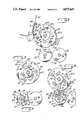
- FIGS. 1, 2, 3 and 4 are simplified elevational views illustrating sequences in operation of the present machine
- FIG. 5 is an end elevation of the machine, on an enlarged scale compared to FIGS. 1-4;
- FIG. 6 is a sectional view substantially on the lines 6--6 of FIG. 5;
- FIG. 7 is a sectional detail view substantially on the lines 7--7 of FIG. 5, showing the operating details for the wipers;
- FIG. 8 is a sectional view illustrating in detail the manner in which a wiper cooperates in timed relationship with the gripper mechanism on the lap cylinder;
- FIG. 9 is a detail view of the gripper mechanism of the lap cylinder and opening cylinder in a gripping condition.
- FIG. 5 is a scale drawing showing the general spaced relationship of the parts associated with the extracting cylinder.
- FIGS. 1-4 are for the most part schematic illustrations of the sequence of operation.
- signatures S are supplied from a hopper 20, FIG. 1.
- Each signature may be viewed simply as a folded sheet which is to be withdrawn from the hopper 20 and carried around to a register gauge 22, FIG. 2, where it is released.
- the signature thus released is next to be clamped at its free edges by respective clamps on a lap cylinder 24 and an opening cylinder 26, FIG. 3.
- These clamps eventually diverge, FIG. 4, and are opened to drop the signature onto a saddle conveyor 28.
- each cylinder 24 and 26 will be termed herein the opening cylinder, as each has that role.
- the signatures are extracted from the hopper one by one in sequence by grippers as 30-1, FIG. 1, supported on an extracting cylinder 32.
- the term "extracting cylinder” is a term of art and in reality includes a pair of discs as 32-1 and 32-2, FIG. 5, keyed for rotation on a driven shaft 34. There are two other discs included as part of the extracting cylinder as will be explained.
- the grippers are arranged in pairs (a pair of grippers 30-2, FIG. 5) supported on a rock shaft 36.
- This rock shaft extends through openings in the extracting cylinder. It is supported rotatably in a hub 36H secured to a disc 32-3, keyed to shaft 34.
- Cam 44 has a lobe or high part 44H and a spring 50 for each segment gear, FIG. 6, tends to hold the cam follower 42 against the cam 44 to follow the contour thereof. This spring tends to close the gripper as 30-1 whereas the high part 44H of the cam rocks the gear segment and its pinion to open the gripper.
- the extracting cylinder may have several sets of grippers as will be explained.
- Gripper 30-1 is shown in FIG. 1 in its closed position, effective to clamp the backbone of a extracted signature being extracted against a cooperating anvil 30A on the extracting cylinder.
- suction cups 51 were effective to apply suction to and partly extract the folded lower part of the signature (backbone) to locate the fold of the signature in position to be clamped against the anvil 30A.
- the suction cups are supported by hollow tubes 52 connected to a source of vacuum.
- the signature thus picked up by the paired grippers 30-1 moves counterclockwise on and with the extracting cylinder assembly 32 until the fold or backbone is against the register gauge 22 and at this time the grippers 30-1 are opened to release the signature.
- the register gauge will be so positioned that the signature released thereto will have its lap margin accurately positioned as will be described in connection with operation of the opening cylinders 24 and 26. It may be mentioned in this connection that in FIGS. 1 and 2 no attempt is made to necessarily depict in an accurate rotational sense the exact position of the two cylinders 24 and 26 with respect to any particular position of the extracting cylinder 32.
- the timing cam 44 which times opening and closing of the grippers, will be positioned initially at the time of installation so that the grippers will close properly on the backbone of the signature presented by the suction cups. Likewise the register gauge will be properly adjusted. Then, an adjustable cam patch 55, FIG. 5, on cam 44 is turned to lengthen or shorten the effective cam dwell surface (depending on the signature length) to allow the grippers to be opened by the cam lobe 44H just when the signature backbone is at the register gauge; the grippers remain open with the cam follower 42 riding on the cam lobe until they are once more back on the hopper side when the cam follower rides off the cam lobe, allowing the gripper spring to close the gripper.
- the signatures are unevenly folded so that there is a long leg with a lap margin LM, FIGS. 1 and 6.
- the lap margin is not large and the present invention for the most part is concerned with wipers or tucker fingers which assure the lap margin will be presented to a clamp assembly located within a large notch 24N on the perimeter of the opening cylinder 24 as will now be described.
- the extracting cylinder 32 is equipped with sets of wipers or tucker blades 60, FIG. 2, of which there may be as many as three sets 60, 60-1 and 60-2 as shown in FIG. 3.
- the wipers are thus synchronized in an absolute sense with the extracting cylinder.
- a wiper finger 60 is shown in its retracted or inoperable position, approximately as the signature S is reaching the register gauge 22.
- FIG. 3 the signature S has been released and the wiper finger 60 is actuated to its operable position where it engages the trailing edge of the signature to force it into the notch section of the cylinder 24.
- each wiper 60 is secured to a rock shaft 62 rotatably supported in a hub secured to a disc 64, just as each rock shaft as 36 for the signature clamps as 30-1, 30-1 is supported by the disc 32-3 as described above.
- disc 64 is keyed to the extracting cylinder shaft 34 so that it is part of the extracting cylinder in the collective sense as the term "extracting cylinder” is understood in the art.
- the rock shafts for the wiper extend freely through openings in the discs 32-1 and 32-2.
- each rock shaft 62 which carries a pair of wipers as 60 is provided at one end with a pinion gear 66, FIG. 5, meshed with a related segment gear 68.
- the segment gear is provided with a cam follower 70 opposed to a cam 72.
- the cam 72 like the cam 44, is fixed.
- the cam 72 has a high part or lobe 72H.
- Each segment gear 68 is spring-biased so that its follower 70 is urged against the perimeter of the cam 72.
- the cam lobe 72H is configured and positioned so that the segment gear is oscillated to rotate its pinion 66 counterclockwise as viewed in FIG. 7, positioning the wiper 60 in its operable position, at the time the fold or backbone of the signature is against the register gauge 22, and this also coincides in time with the trailing edge of the large notch in cylinder 24 attaining a position where its clamp structure 75, FIG. 8, is ready to capture the extended margin LM.
- the timing is such that the wipers are actuated to their effective position as a gripper set 75 (opening cylinder) is opposed to or adjacent the free edge of the signature released to the register gauge.
- each rock shaft 62 may be equipped with several wipers 60 and indeed in most instances will be so equipped.
- the wipers 60 may thus be located at the outside of the extracting cylinder discs 32-1, 32-2 or between them especially if there are only two sets of grippers on the extracting cylinder 180° apart leaving ample room for two sets of wipers. This is of particular advantage and significance because, depending upon the texture and size of the paper signature, the wipers may be more effective on the middle of the signature than on the outer margins.
- the gripper assembly 75 (or set) on cylinder 24 comprises a main gripper 76 having a hub 77 secured to a rock shaft 78, FIG. 8.
- the main gripper is opposed to a gripper seat 80 at the trailing edge of the lap cylinder notch 24N.
- the short gripper 82 projects from a collar (not shown) loosely mounted on the rock shaft 78, compared to the hub 77 of the main gripper 76 which is secured to the rock shaft 78.
- Actuation of the main gripper is effected by an arm 83 extending from the hub 77 and a strong spring 86 tends to hold a cam follower 88 on arm 83 against the perimeter of a fixed control cam 90.
- the spring 86 tends to close the clamp 76.
- the cylinder 24 is keyed to a driven shaft 92 in turn driven by a chain 94, FIG. 5, connected to a sprocket at one end of shaft 34.
- the chain 94 and related sprockets will have a drive ratio matched or synchronized to the delivery of signatures from the extracting cylinder.
- Shaft 96, FIG. 8, for the opening cylinder 26 will be geared to shaft 92 in a 1:1 ratio at all times. If the extracting cylinder is to extract three signatures per cycle, then cylinders 24,26 will be rotated three turns for one turn of the extracting cylinder.
- Cylinder 24 with its clamp or gripper assembly rotates about the cam 90; cam 90 is responsible for operating the gripper assembly 75 as will now be described.
- Cam 90 has a short dwell 90a (low part of the cam) and when the follower 88 is on this part of cam 90, just at the commencement as shown in FIG. 8, the clamping structure 75 is conditioned for closing under the effect of spring 86.
- the two clamps thus respectively engage the lap margin LM (short clamp 82) and the free margin of the shorter sheet is engaged by the longer clamp 76.
- both clamps With both clamps being closed on the free margins of the released signature, the latter is stripped out of the register gauge and is rapidly flexed about a guide 95.
- cylinder 26 and its clamp 97 starts to approach the notch in the opposed opening cylinder 24.
- the cam 90 has a second low part or dwell 90b.
- the longer clamp 76 commences to undergo a retraction and the free edge of the short sheet is released so that it may be clamped and captured by clamp 97 on the opening cylinder 26.
- This is a difficult motion to visualize but by looking at FIG. 3 it can be perceived that if the free edge of the short leg of the signature be imagined as located at point X, with gripper 97 also at point X, clamp 97 just at the moment it passes point X can be closed to clamp the free margin of the short leg of the signature.
- Gripper 97 is operated by a cam and cam follower (not shown) as is well known. Also, there may be sets of grippers on the opening cylinders, 180° apart, depending upon the delivery rate.
- the number of gripper sets on the extracting cylinder and opening cylinders may vary but the timing will always be such that the wipers are effective when the opening cylinder gripper as 75 is adjacent the free edges of the signature to be opened and released to the saddle conveyor.
- FIGS. 2 and 8 the free edges of the signature are unsupported and tend to fall (droop) downward toward the opening cylinder.
- the wipers are moved from their retracted position within (at or inside) the perimeter of the opening cylinder discs, FIGS. 2 and 7, to their actuated position, extended beyond said perimeter, forcefully to press or nudge the unsupported free edge of the signature into the gap between the gripper 76 and its opposed gripper seat 80, FIG. 8. It will also be observed, FIG.
- the register gauge is adjustable, but once adjusted for a particular signature is fixed, always to assure the signature released thereto is in position to have its free edges opened in the manner already explained.
Landscapes
- Engineering & Computer Science (AREA)
- Mechanical Engineering (AREA)
- Feeding Of Articles By Means Other Than Belts Or Rollers (AREA)
- Collation Of Sheets And Webs (AREA)
- Folding Of Thin Sheet-Like Materials, Special Discharging Devices, And Others (AREA)
Abstract
Description
Claims (15)
Priority Applications (1)
| Application Number | Priority Date | Filing Date | Title |
|---|---|---|---|
| US07/246,910 US4875669A (en) | 1987-09-23 | 1988-09-16 | Signature gathering machines |
Applications Claiming Priority (2)
| Application Number | Priority Date | Filing Date | Title |
|---|---|---|---|
| US10027387A | 1987-09-23 | 1987-09-23 | |
| US07/246,910 US4875669A (en) | 1987-09-23 | 1988-09-16 | Signature gathering machines |
Related Parent Applications (1)
| Application Number | Title | Priority Date | Filing Date |
|---|---|---|---|
| US10027387A Continuation-In-Part | 1987-09-23 | 1987-09-23 |
Publications (1)
| Publication Number | Publication Date |
|---|---|
| US4875669A true US4875669A (en) | 1989-10-24 |
Family
ID=26796982
Family Applications (1)
| Application Number | Title | Priority Date | Filing Date |
|---|---|---|---|
| US07/246,910 Expired - Fee Related US4875669A (en) | 1987-09-23 | 1988-09-16 | Signature gathering machines |
Country Status (1)
| Country | Link |
|---|---|
| US (1) | US4875669A (en) |
Cited By (3)
| Publication number | Priority date | Publication date | Assignee | Title |
|---|---|---|---|---|
| US5893824A (en) * | 1996-08-13 | 1999-04-13 | Heidelberg Finishing Systems, Inc. | Transfer drum assembly for signature handling |
| US6308945B1 (en) | 1998-09-28 | 2001-10-30 | Grapha-Holding Ag | Apparatus for placing folded signatures on a transport device |
| US20050285333A1 (en) * | 2004-06-23 | 2005-12-29 | Pitney Bowes Deutschland Gmbh | Rotary feeder for conveying enclosures |
Citations (5)
| Publication number | Priority date | Publication date | Assignee | Title |
|---|---|---|---|---|
| US2413358A (en) * | 1944-04-11 | 1946-12-31 | Tw & Cb Sheridan Co | Signature gathering machine |
| US3809384A (en) * | 1972-07-13 | 1974-05-07 | Harris Intertype Corp | Saddle gathering machine |
| US4180255A (en) * | 1977-12-27 | 1979-12-25 | Harris Corporation | Wiper system inserter |
| US4299378A (en) * | 1977-05-30 | 1981-11-10 | Grapha-Holding Ag | Apparatus for singularizing and opening stacked folded sheets |
| US4625952A (en) * | 1985-07-22 | 1986-12-02 | R. R. Donnelley & Sons | Signature inserter |
-
1988
- 1988-09-16 US US07/246,910 patent/US4875669A/en not_active Expired - Fee Related
Patent Citations (5)
| Publication number | Priority date | Publication date | Assignee | Title |
|---|---|---|---|---|
| US2413358A (en) * | 1944-04-11 | 1946-12-31 | Tw & Cb Sheridan Co | Signature gathering machine |
| US3809384A (en) * | 1972-07-13 | 1974-05-07 | Harris Intertype Corp | Saddle gathering machine |
| US4299378A (en) * | 1977-05-30 | 1981-11-10 | Grapha-Holding Ag | Apparatus for singularizing and opening stacked folded sheets |
| US4180255A (en) * | 1977-12-27 | 1979-12-25 | Harris Corporation | Wiper system inserter |
| US4625952A (en) * | 1985-07-22 | 1986-12-02 | R. R. Donnelley & Sons | Signature inserter |
Cited By (4)
| Publication number | Priority date | Publication date | Assignee | Title |
|---|---|---|---|---|
| US5893824A (en) * | 1996-08-13 | 1999-04-13 | Heidelberg Finishing Systems, Inc. | Transfer drum assembly for signature handling |
| US6308945B1 (en) | 1998-09-28 | 2001-10-30 | Grapha-Holding Ag | Apparatus for placing folded signatures on a transport device |
| US20050285333A1 (en) * | 2004-06-23 | 2005-12-29 | Pitney Bowes Deutschland Gmbh | Rotary feeder for conveying enclosures |
| US7478810B2 (en) * | 2004-06-23 | 2009-01-20 | Pitney Bowes Deutschland Gmbh | Rotary feeder with cam actuated claw members |
Similar Documents
| Publication | Publication Date | Title |
|---|---|---|
| RU1830023C (en) | Machine for making double-chamber tea-filled packs | |
| US3809384A (en) | Saddle gathering machine | |
| US2413358A (en) | Signature gathering machine | |
| US3777683A (en) | Apparatus for manufacturing loops of elasticised material | |
| EP0224295A1 (en) | Device for conveying a bundel of sheets | |
| JP2646191B2 (en) | A device that staples folded multi-leaf prints | |
| US6015145A (en) | Separator guide for Z-folded sheets | |
| US2251943A (en) | Signature gathering machine | |
| US3842568A (en) | Method of packaging flexible plastic bags | |
| EP0590568B1 (en) | System comprising an apparatus for the continuous feeding of boxes to a machine known as a box filler and a box filler | |
| GB2148188A (en) | Producing pads with pronged wire binding strips | |
| US5050851A (en) | Machine for placing inserts between the panels of folded sheets | |
| US2301016A (en) | Machine for wrapping rolls of toilet paper and the like | |
| US4875669A (en) | Signature gathering machines | |
| US4180255A (en) | Wiper system inserter | |
| US5277413A (en) | Rotary signature gathering apparatus with sheet stop | |
| US4383683A (en) | Apparatus for separating the bottom sheet of a stack or sheets | |
| US2025527A (en) | Book signature feed | |
| US3806111A (en) | Signature inserter | |
| EP0308853B1 (en) | Signature gathering machines | |
| US3463484A (en) | Sheet gripping control mechanism for printing machines | |
| US3481594A (en) | Signature feeding apparatus | |
| US3032336A (en) | Collator and stitcher | |
| US3591165A (en) | Method and apparatus for handling sheet material, signatures and the like | |
| US4511130A (en) | Phase controlled gripper operating system for collator |
Legal Events
| Date | Code | Title | Description |
|---|---|---|---|
| AS | Assignment |
Owner name: MCCAIN MANUFACTURING CORPORATION, 6200 WEST 60TH S Free format text: ASSIGNMENT OF ASSIGNORS INTEREST.;ASSIGNORS:MC CAIN, WILLIAM B.;HIGGINS, GEORGE D.;REEL/FRAME:004998/0721 Effective date: 19880912 Owner name: MCCAIN MANUFACTURING CORPORATION, ILLINOIS Free format text: ASSIGNMENT OF ASSIGNORS INTEREST;ASSIGNORS:MC CAIN, WILLIAM B.;HIGGINS, GEORGE D.;REEL/FRAME:004998/0721 Effective date: 19880912 |
|
| AS | Assignment |
Owner name: LAKE SHORE NATIONAL BANK Free format text: SECURITY INTEREST;ASSIGNOR:MCCAIN MANUFACTURING CORPORATION, AN CORP. OF IL;REEL/FRAME:006269/0215 Effective date: 19920605 |
|
| FEPP | Fee payment procedure |
Free format text: PAT HLDR NO LONGER CLAIMS SMALL ENT STAT AS INDIV INVENTOR (ORIGINAL EVENT CODE: LSM1); ENTITY STATUS OF PATENT OWNER: SMALL ENTITY |
|
| FPAY | Fee payment |
Year of fee payment: 4 |
|
| AS | Assignment |
Owner name: GENERAL ELECTRIC CAPITAL CORPORATION, ILLINOIS Free format text: PATENT SECURITY AGREEMENT;ASSIGNOR:MCCAIN MANUFACTURING CORP.;REEL/FRAME:007558/0487 Effective date: 19950602 Owner name: MCCAIN MANUFACTURING CORP., ILLINOIS Free format text: RELEASE BY SECURED PARTY;ASSIGNOR:AMERICAN NATIONAL BANK AND TRUST COMPANY OF CHICAGO (FORMERLY KNOWN AS LAKE SHORE NATIONAL BANK);REEL/FRAME:007521/0808 Effective date: 19950602 |
|
| FEPP | Fee payment procedure |
Free format text: PAT HOLDER CLAIMS SMALL ENTITY STATUS - SMALL BUSINESS (ORIGINAL EVENT CODE: SM02); ENTITY STATUS OF PATENT OWNER: SMALL ENTITY |
|
| FEPP | Fee payment procedure |
Free format text: PAYOR NUMBER ASSIGNED (ORIGINAL EVENT CODE: ASPN); ENTITY STATUS OF PATENT OWNER: SMALL ENTITY |
|
| FPAY | Fee payment |
Year of fee payment: 8 |
|
| AS | Assignment |
Owner name: MCCAIN BINDERY SYSTEMS, INC., INDIANA Free format text: ASSIGNMENT OF ASSIGNORS INTEREST;ASSIGNOR:MCCAIN MANUFACTURING CORPORATION;REEL/FRAME:008842/0311 Effective date: 19970708 |
|
| REMI | Maintenance fee reminder mailed | ||
| LAPS | Lapse for failure to pay maintenance fees | ||
| STCH | Information on status: patent discontinuation |
Free format text: PATENT EXPIRED DUE TO NONPAYMENT OF MAINTENANCE FEES UNDER 37 CFR 1.362 |
|
| FP | Lapsed due to failure to pay maintenance fee |
Effective date: 20011024 |