US4864840A - Riveting head for stapling apparatus - Google Patents
Riveting head for stapling apparatus Download PDFInfo
- Publication number
- US4864840A US4864840A US07/025,229 US2522987A US4864840A US 4864840 A US4864840 A US 4864840A US 2522987 A US2522987 A US 2522987A US 4864840 A US4864840 A US 4864840A
- Authority
- US
- United States
- Prior art keywords
- covering body
- lever
- pulling unit
- stapling apparatus
- head
- Prior art date
- Legal status (The legal status is an assumption and is not a legal conclusion. Google has not performed a legal analysis and makes no representation as to the accuracy of the status listed.)
- Expired - Fee Related
Links
- 230000008878 coupling Effects 0.000 claims abstract 4
- 238000010168 coupling process Methods 0.000 claims abstract 4
- 238000005859 coupling reaction Methods 0.000 claims abstract 4
- 230000000284 resting effect Effects 0.000 claims description 4
- 239000011435 rock Substances 0.000 description 2
- 238000010348 incorporation Methods 0.000 description 1
- 238000004519 manufacturing process Methods 0.000 description 1
- 239000000463 material Substances 0.000 description 1
- 238000005259 measurement Methods 0.000 description 1
- 230000004048 modification Effects 0.000 description 1
- 238000012986 modification Methods 0.000 description 1
Images

Classifications
-
- B—PERFORMING OPERATIONS; TRANSPORTING
- B21—MECHANICAL METAL-WORKING WITHOUT ESSENTIALLY REMOVING MATERIAL; PUNCHING METAL
- B21J—FORGING; HAMMERING; PRESSING METAL; RIVETING; FORGE FURNACES
- B21J15/00—Riveting
- B21J15/38—Accessories for use in connection with riveting, e.g. pliers for upsetting; Hand tools for riveting
- B21J15/386—Pliers for riveting
-
- B—PERFORMING OPERATIONS; TRANSPORTING
- B21—MECHANICAL METAL-WORKING WITHOUT ESSENTIALLY REMOVING MATERIAL; PUNCHING METAL
- B21J—FORGING; HAMMERING; PRESSING METAL; RIVETING; FORGE FURNACES
- B21J15/00—Riveting
- B21J15/02—Riveting procedures
- B21J15/04—Riveting hollow rivets mechanically
- B21J15/043—Riveting hollow rivets mechanically by pulling a mandrel
-
- Y—GENERAL TAGGING OF NEW TECHNOLOGICAL DEVELOPMENTS; GENERAL TAGGING OF CROSS-SECTIONAL TECHNOLOGIES SPANNING OVER SEVERAL SECTIONS OF THE IPC; TECHNICAL SUBJECTS COVERED BY FORMER USPC CROSS-REFERENCE ART COLLECTIONS [XRACs] AND DIGESTS
- Y10—TECHNICAL SUBJECTS COVERED BY FORMER USPC
- Y10T—TECHNICAL SUBJECTS COVERED BY FORMER US CLASSIFICATION
- Y10T29/00—Metal working
- Y10T29/50—Convertible metal working machine
-
- Y—GENERAL TAGGING OF NEW TECHNOLOGICAL DEVELOPMENTS; GENERAL TAGGING OF CROSS-SECTIONAL TECHNOLOGIES SPANNING OVER SEVERAL SECTIONS OF THE IPC; TECHNICAL SUBJECTS COVERED BY FORMER USPC CROSS-REFERENCE ART COLLECTIONS [XRACs] AND DIGESTS
- Y10—TECHNICAL SUBJECTS COVERED BY FORMER USPC
- Y10T—TECHNICAL SUBJECTS COVERED BY FORMER US CLASSIFICATION
- Y10T29/00—Metal working
- Y10T29/53—Means to assemble or disassemble
- Y10T29/53709—Overedge assembling means
- Y10T29/53717—Annular work
- Y10T29/53726—Annular work with second workpiece inside annular work one workpiece moved to shape the other
- Y10T29/5373—Annular work with second workpiece inside annular work one workpiece moved to shape the other comprising driver for snap-off-mandrel fastener; e.g., Pop [TM] riveter
Definitions
- the present invention is concerned with a riveting head which may be fitted onto a stapling apparatus, by means of which it is possible to take advantage of the operating mechanism for the staple driver of such apparatus to power a riveting unit of the kind using rivet means made of a stem with a frangible riveting head at one end thereof. Therefore, one and the same apparatus becomes adapted for two different applications and may be used for stapling, according to its usual embodiment, or for riveting purposes, when the riveting head to be described is coupled thereto.
- the force is attained by implementing the apparatus with a lever having a long operating arm, in order to multiply the forces applied to the grip thereof.
- the riveting head that is the subject of the present invention and is adapted for fitting into manual operation stapler apparatus, has been devised.
- the riveting head in question essentially comprises a box-like body provided with means for its removable engagement to the stapling head body of a manually operated stapler apparatus.
- a riveting unit of a known configuration, with a stem rivet pulling device or unit axially displaceable therein and formed with the rivet stem holding nip.
- the pulling device or unit has means for pivotally connecting a lever in turn articulated on the body itself and extended in a pawl which protrudes from the riveting head body or box and comes to a position within the stapling body which is in adjacent relation to the operating trigger of the stapler driving mechanism.
- the head comprises as well means for returning the rivet pulling unit and the lever articulated to the latter towards their rest position once a riveting operation has been performed.
- a pusher protrudes outside the riveting head box and thus forms a push-button resting onto the lever articulated to the pulling unit or device, to return the ensemble of the riveting mechanism to its rest position.
- the end of the rivet pulling device or unit opposite to that where the rivet stem retaining nip is placed extends in a pair of wings in the manner of a fork and has between these wings a stub shaft about which the operating lever for the rivet stem pulling device is mounted, the lever being articulated at one end thereof onto an axle fixed within the riveting head body or box, the opposite end thereof constituting the pawl which is to be operated by the stapler apparatus lever.
- FIG. 1 is a longitudinal sectional view of the riveting head according to the invention as incorporated in a manually operated stapling apparatus shown in the rest position;
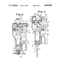
- FIG. 2 is a view similar to FIG. 1 showing the ensemble of the mechanism in its working position
- FIG. 3 is a similar view showing the returning of the riveting head parts to their rest position.
- the riveting head adapted for engagement to a manually operated stapling apparatus comprises, in the drawings, a box or cover 1 provided with wings 2 or another suitable means for removably connecting it to the stapling head of a stapler apparatus 3 which is manually operable by means of a lever 4 formed with a trigger 5 for operation of the staple driver mechanism of the stapler apparatus.
- a riveting unit 6 is mounted within the box 1 and has its rivet stem holding nip 7, of a conventional configuration, guided within a cavity 8 of the box and terminated at its lowermost working end in an anvil bushing 9.
- a pair of wings 10 forming a type of a fork is provided at the end of the riveting or pulling unit 6 opposite to that which carries the rivet holding nip 7 and is supported on a shaft 11 about which a second class lever 12 is mounted or articulated, this lever being articulated at one end thereof about an axle 13 mounted within the body 1, while its other end forms a pawl 14 protruding outside the riveting head body 1 through a window 15 which, in the assembled head body 1, comes in juxtaposed relation to a window 16 of the stapling head of stapling apparatus 3, and rests upon the trigger 5 of the operating lever 4 of the latter.
- An opening 17 is formed in the cover body 1, and a push-button 18 protrudes therethrough and has a rounded head 19 resting on the riveting head lever 12.
- the riveting head operates as follows: once the eyelet 20 to be riveted has been placed with its stem 21, and thus the head 21a, in the position for riveting a pair of plates 22, or whatever component in which the rivet is to be placed, the stem 21 being suitably secured by the nip 7, with the anvil 9 resting against the components 22 (FIG. 1), a force applied by hand to the operating lever 4 of the stapling apparatus is transmitted to the trigger 5 of the lever and from this latter to the pawl 14 of the riveting head lever 12.
- the lever 12 multiplies the force, rocks about the fixed axis 13 and draws, through wings 10, the riveting unit 6 carrying the nip 7, with a force enough for the head 21a of the riveting stem to perform riveting of the eyelet 20 (FIG. 2) as well as breaking of the head 21a.
- the head 21a becomes separated from the stem 21 and both may be removed from both sides of the components.
- the used stem rivet can be removed from the nip 7 and substituted by a new one.
- the rivet 20 is of a well known kind that can be inserted in a rivet receiving drill-hole from one side of the components to be affixed and is riveted at the other side of the same, thus providing some advantages in its placing.
- a stapling apparatus can be adapted for performing the function of a riveting apparatus, without the need for making fundamental modification in the operating system of the stapler.
Landscapes
- Engineering & Computer Science (AREA)
- Mechanical Engineering (AREA)
- Portable Nailing Machines And Staplers (AREA)
- Dowels (AREA)
- Dovetailed Work, And Nailing Machines And Stapling Machines For Wood (AREA)
Abstract
Description
Claims (9)
Applications Claiming Priority (2)
| Application Number | Priority Date | Filing Date | Title |
|---|---|---|---|
| ES293.060 | 1986-03-19 | ||
| ES1986293060U ES293060Y (en) | 1986-03-19 | 1986-03-19 | RIVETING HEAD COUPLABLE TO STAPLING MACHINES |
Publications (1)
| Publication Number | Publication Date |
|---|---|
| US4864840A true US4864840A (en) | 1989-09-12 |
Family
ID=8440306
Family Applications (1)
| Application Number | Title | Priority Date | Filing Date |
|---|---|---|---|
| US07/025,229 Expired - Fee Related US4864840A (en) | 1986-03-19 | 1987-03-12 | Riveting head for stapling apparatus |
Country Status (6)
| Country | Link |
|---|---|
| US (1) | US4864840A (en) |
| EP (1) | EP0239517B1 (en) |
| AT (1) | ATE59155T1 (en) |
| CA (1) | CA1316377C (en) |
| DE (1) | DE3766733D1 (en) |
| ES (1) | ES293060Y (en) |
Cited By (2)
| Publication number | Priority date | Publication date | Assignee | Title |
|---|---|---|---|---|
| US5093930A (en) * | 1988-11-28 | 1992-03-03 | U.S. Philips Corporation | Directly mixing synchronous am receiver |
| US20040211045A1 (en) * | 2001-08-20 | 2004-10-28 | Helmut Frey | Holding device for a tarpaulin-like or cloth-like object to be processed |
Families Citing this family (3)
| Publication number | Priority date | Publication date | Assignee | Title |
|---|---|---|---|---|
| US4913332A (en) * | 1989-01-23 | 1990-04-03 | Swingline Inc. | Sheath release device for stapler |
| CN105522098B (en) * | 2016-02-28 | 2017-11-21 | 张新丁 | The manual staking that a kind of one-handed performance is worked continuously clamps automatic binding device and application |
| CN110038994B (en) * | 2019-05-29 | 2024-09-17 | 苏州斯旺西智能装备科技有限公司 | Nailing gun and riveting method |
Citations (5)
| Publication number | Priority date | Publication date | Assignee | Title |
|---|---|---|---|---|
| US2075162A (en) * | 1934-04-04 | 1937-03-30 | Breeze Corp | Rivet setting device |
| US3802519A (en) * | 1972-02-15 | 1974-04-09 | Usm Corp | Self-contained power device |
| US4344311A (en) * | 1980-03-19 | 1982-08-17 | Lobster Tool Co., Ltd. | Riveter |
| GB2126142A (en) * | 1982-07-26 | 1984-03-21 | Petrus Ind | Riveting |
| US4619394A (en) * | 1984-07-19 | 1986-10-28 | Arrow Fastener Company, Inc. | Riveting attachment for a staple gun |
Family Cites Families (2)
| Publication number | Priority date | Publication date | Assignee | Title |
|---|---|---|---|---|
| US2097051A (en) * | 1934-09-04 | 1937-10-26 | Acme Staple Company | Fastening device |
| DE3124648C2 (en) * | 1981-06-23 | 1986-05-28 | Nihon Nejimawashi Co., Ltd., Osaka | "Hand rivet head setter" |
-
1986
- 1986-03-19 ES ES1986293060U patent/ES293060Y/en not_active Expired
-
1987
- 1987-03-12 US US07/025,229 patent/US4864840A/en not_active Expired - Fee Related
- 1987-03-17 DE DE8787500010T patent/DE3766733D1/en not_active Expired - Fee Related
- 1987-03-17 AT AT87500010T patent/ATE59155T1/en not_active IP Right Cessation
- 1987-03-17 EP EP87500010A patent/EP0239517B1/en not_active Expired - Lifetime
- 1987-03-17 CA CA000533517A patent/CA1316377C/en not_active Expired - Fee Related
Patent Citations (5)
| Publication number | Priority date | Publication date | Assignee | Title |
|---|---|---|---|---|
| US2075162A (en) * | 1934-04-04 | 1937-03-30 | Breeze Corp | Rivet setting device |
| US3802519A (en) * | 1972-02-15 | 1974-04-09 | Usm Corp | Self-contained power device |
| US4344311A (en) * | 1980-03-19 | 1982-08-17 | Lobster Tool Co., Ltd. | Riveter |
| GB2126142A (en) * | 1982-07-26 | 1984-03-21 | Petrus Ind | Riveting |
| US4619394A (en) * | 1984-07-19 | 1986-10-28 | Arrow Fastener Company, Inc. | Riveting attachment for a staple gun |
Cited By (3)
| Publication number | Priority date | Publication date | Assignee | Title |
|---|---|---|---|---|
| US5093930A (en) * | 1988-11-28 | 1992-03-03 | U.S. Philips Corporation | Directly mixing synchronous am receiver |
| US20040211045A1 (en) * | 2001-08-20 | 2004-10-28 | Helmut Frey | Holding device for a tarpaulin-like or cloth-like object to be processed |
| US6996890B2 (en) * | 2001-08-20 | 2006-02-14 | Helmut Frey | Holding device for a tarpaulin-like or cloth-like object to be processed |
Also Published As
| Publication number | Publication date |
|---|---|
| ATE59155T1 (en) | 1991-01-15 |
| CA1316377C (en) | 1993-04-20 |
| DE3766733D1 (en) | 1991-01-31 |
| EP0239517A1 (en) | 1987-09-30 |
| ES293060U (en) | 1986-07-01 |
| EP0239517B1 (en) | 1990-12-19 |
| ES293060Y (en) | 1987-03-16 |
Similar Documents
| Publication | Publication Date | Title |
|---|---|---|
| USRE46857E1 (en) | Electric blind rivet setting device | |
| EP0116954A2 (en) | A riveting motor tool | |
| GB1376064A (en) | Rivet setting tool for blind rivets | |
| US4864840A (en) | Riveting head for stapling apparatus | |
| US3154210A (en) | Rivet setting tools | |
| US3302444A (en) | Adjustable rivet setting tools | |
| EP0468717B1 (en) | Blind riveting tool | |
| EP0286296A2 (en) | Fastener installation apparatus | |
| US4088004A (en) | Fastening tool device | |
| US5899374A (en) | Magazine securing assembly for stapling machines | |
| US3601880A (en) | Metal-working tool | |
| US3190104A (en) | Automatic pull gun | |
| US1725301A (en) | Wrench | |
| US2466856A (en) | Staple driving device | |
| US3277689A (en) | Fully automatic rivet gun | |
| US4136547A (en) | Riveter | |
| TW201429643A (en) | Hand riveter | |
| EP0128875A1 (en) | Tool for fixing blind rivets in general, in particular for the wall mounting of metal blocks | |
| SU1299698A1 (en) | Hand tool for single-sided rivetting | |
| US2569220A (en) | Tacking machine | |
| US3334509A (en) | Mandrel separable fastener inserting tools | |
| EP1262259A1 (en) | A hand riveting tool | |
| JPS6343176B2 (en) | ||
| US2575416A (en) | Handle-actuated blind riveting tool | |
| US2934234A (en) | Rivet expander tool |
Legal Events
| Date | Code | Title | Description |
|---|---|---|---|
| AS | Assignment |
Owner name: ESSELTE BUSINESS SYSTEMS, S.A., VIA AUGUSTA, 20-26 Free format text: ASSIGNMENT OF ASSIGNORS INTEREST.;ASSIGNOR:GRAU PEREZ, JORGE;REEL/FRAME:004710/0537 Effective date: 19870414 |
|
| AS | Assignment |
Owner name: ESSELTE BUSINESS SYSTEMS, S.A., VIA AUGUSTA, 20-26 Free format text: ASSIGNMENT OF ASSIGNORS INTEREST.;ASSIGNOR:GRAU PEREZ, JORGE;REEL/FRAME:004713/0534 Effective date: 19870414 Owner name: ESSELTE BUSINESS SYSTEMS, S.A.,SPAIN Free format text: ASSIGNMENT OF ASSIGNORS INTEREST;ASSIGNOR:GRAU PEREZ, JORGE;REEL/FRAME:004713/0534 Effective date: 19870414 |
|
| CC | Certificate of correction | ||
| FEPP | Fee payment procedure |
Free format text: PAT HLDR NO LONGER CLAIMS SMALL ENT STAT AS INDIV INVENTOR (ORIGINAL EVENT CODE: LSM1); ENTITY STATUS OF PATENT OWNER: LARGE ENTITY Free format text: PAYOR NUMBER ASSIGNED (ORIGINAL EVENT CODE: ASPN); ENTITY STATUS OF PATENT OWNER: LARGE ENTITY |
|
| FPAY | Fee payment |
Year of fee payment: 4 |
|
| REMI | Maintenance fee reminder mailed | ||
| AS | Assignment |
Owner name: ESSELTE, S.A., SPAIN Free format text: CHANGE OF NAME;ASSIGNOR:ESSELTE BUSINESS SYSTEMS, S.A.;REEL/FRAME:008579/0662 Effective date: 19940128 |
|
| LAPS | Lapse for failure to pay maintenance fees | ||
| FP | Lapsed due to failure to pay maintenance fee |
Effective date: 19970917 |
|
| STCH | Information on status: patent discontinuation |
Free format text: PATENT EXPIRED DUE TO NONPAYMENT OF MAINTENANCE FEES UNDER 37 CFR 1.362 |