US4864702A - Five axis riveter - Google Patents
Five axis riveter Download PDFInfo
- Publication number
- US4864702A US4864702A US07/129,929 US12992987A US4864702A US 4864702 A US4864702 A US 4864702A US 12992987 A US12992987 A US 12992987A US 4864702 A US4864702 A US 4864702A
- Authority
- US
- United States
- Prior art keywords
- workpiece
- frame
- supporting surface
- riveting
- moving
- Prior art date
- Legal status (The legal status is an assumption and is not a legal conclusion. Google has not performed a legal analysis and makes no representation as to the accuracy of the status listed.)
- Expired - Lifetime
Links
Images


Classifications
-
- B—PERFORMING OPERATIONS; TRANSPORTING
- B23—MACHINE TOOLS; METAL-WORKING NOT OTHERWISE PROVIDED FOR
- B23Q—DETAILS, COMPONENTS, OR ACCESSORIES FOR MACHINE TOOLS, e.g. ARRANGEMENTS FOR COPYING OR CONTROLLING; MACHINE TOOLS IN GENERAL CHARACTERISED BY THE CONSTRUCTION OF PARTICULAR DETAILS OR COMPONENTS; COMBINATIONS OR ASSOCIATIONS OF METAL-WORKING MACHINES, NOT DIRECTED TO A PARTICULAR RESULT
- B23Q5/00—Driving or feeding mechanisms; Control arrangements therefor
- B23Q5/22—Feeding members carrying tools or work
- B23Q5/34—Feeding other members supporting tools or work, e.g. saddles, tool-slides, through mechanical transmission
- B23Q5/38—Feeding other members supporting tools or work, e.g. saddles, tool-slides, through mechanical transmission feeding continuously
- B23Q5/40—Feeding other members supporting tools or work, e.g. saddles, tool-slides, through mechanical transmission feeding continuously by feed shaft, e.g. lead screw
- B23Q5/408—Nut bearings therefor
-
- B—PERFORMING OPERATIONS; TRANSPORTING
- B21—MECHANICAL METAL-WORKING WITHOUT ESSENTIALLY REMOVING MATERIAL; PUNCHING METAL
- B21J—FORGING; HAMMERING; PRESSING METAL; RIVETING; FORGE FURNACES
- B21J15/00—Riveting
- B21J15/10—Riveting machines
- B21J15/14—Riveting machines specially adapted for riveting specific articles, e.g. brake lining machines
- B21J15/142—Aerospace structures
-
- B—PERFORMING OPERATIONS; TRANSPORTING
- B21—MECHANICAL METAL-WORKING WITHOUT ESSENTIALLY REMOVING MATERIAL; PUNCHING METAL
- B21J—FORGING; HAMMERING; PRESSING METAL; RIVETING; FORGE FURNACES
- B21J15/00—Riveting
- B21J15/10—Riveting machines
- B21J15/30—Particular elements, e.g. supports; Suspension equipment specially adapted for portable riveters
-
- B—PERFORMING OPERATIONS; TRANSPORTING
- B23—MACHINE TOOLS; METAL-WORKING NOT OTHERWISE PROVIDED FOR
- B23Q—DETAILS, COMPONENTS, OR ACCESSORIES FOR MACHINE TOOLS, e.g. ARRANGEMENTS FOR COPYING OR CONTROLLING; MACHINE TOOLS IN GENERAL CHARACTERISED BY THE CONSTRUCTION OF PARTICULAR DETAILS OR COMPONENTS; COMBINATIONS OR ASSOCIATIONS OF METAL-WORKING MACHINES, NOT DIRECTED TO A PARTICULAR RESULT
- B23Q1/00—Members which are comprised in the general build-up of a form of machine, particularly relatively large fixed members
- B23Q1/25—Movable or adjustable work or tool supports
- B23Q1/44—Movable or adjustable work or tool supports using particular mechanisms
- B23Q1/48—Movable or adjustable work or tool supports using particular mechanisms with sliding pairs and rotating pairs
-
- Y—GENERAL TAGGING OF NEW TECHNOLOGICAL DEVELOPMENTS; GENERAL TAGGING OF CROSS-SECTIONAL TECHNOLOGIES SPANNING OVER SEVERAL SECTIONS OF THE IPC; TECHNICAL SUBJECTS COVERED BY FORMER USPC CROSS-REFERENCE ART COLLECTIONS [XRACs] AND DIGESTS
- Y10—TECHNICAL SUBJECTS COVERED BY FORMER USPC
- Y10T—TECHNICAL SUBJECTS COVERED BY FORMER US CLASSIFICATION
- Y10T29/00—Metal working
- Y10T29/51—Plural diverse manufacturing apparatus including means for metal shaping or assembling
- Y10T29/5116—Plural diverse manufacturing apparatus including means for metal shaping or assembling forging and bending, cutting or punching
- Y10T29/5118—Riveting
-
- Y—GENERAL TAGGING OF NEW TECHNOLOGICAL DEVELOPMENTS; GENERAL TAGGING OF CROSS-SECTIONAL TECHNOLOGIES SPANNING OVER SEVERAL SECTIONS OF THE IPC; TECHNICAL SUBJECTS COVERED BY FORMER USPC CROSS-REFERENCE ART COLLECTIONS [XRACs] AND DIGESTS
- Y10—TECHNICAL SUBJECTS COVERED BY FORMER USPC
- Y10T—TECHNICAL SUBJECTS COVERED BY FORMER US CLASSIFICATION
- Y10T29/00—Metal working
- Y10T29/53—Means to assemble or disassemble
- Y10T29/53709—Overedge assembling means
- Y10T29/5377—Riveter
- Y10T29/53774—Single header
Definitions
- This invention relates to the art of automatic drilling and riveting machines, and more particularly to a new and improved automatic drilling and riveting machine for operation on major subassemblies.
- One area of use of the present invention is in automatic drilling and riveting of vertically disposed workpieces, although the principles of the present invention can be variously applied.
- An example of such a workpiece is a contoured wing panel rigidly held vertically in a fixture wherein a series of closely-spaced, horizontally disposed stringers are to be riveted to the wing panel.
- Another important consideration is providing an arrangement for supporting the vertically disposed workpiece in a manner which does not interfere with movement and operation of the drilling and riveting machine.
- the present invention provides riveting apparatus for operation on a workpiece having opposite sides and supported on a surface with the sides disposed substantially perpendicular to the supporting surface, the riveting apparatus comprising
- first and second carriage means movably mounted on respective sides of the frame and riveting tools on first and second head means in first and second positioning means on the first and second carriage means, respectively, the tools being movable toward and away from the workpiece.
- the apparatus further comprises means on the frame co-operating with means on the supporting surface for moving the frame in a first direction along the supporting surface and along the workpiece, means on the first and second carriage means co-operating with means on respective sides of the frame for moving the first and second carriage means in a direction substantially perpendicular to the first direction and toward and away from the supporting surfaces, and means for moving the frame in a third direction transverse to the first direction and toward and away from the workpiece.
- the apparatus further comprises means on the first and second head means co-operating with means on the first and second positioning means for moving the first and second head means independently about axes substantially parallel to the first direction and to the supporting surface, and means on the first and second positioning means co-operating with means on the first and second carriage means for moving the first and second head means independently about axes substantially perpendicular to the first direction and to the supporting surface.
- the fixture In a riveting system wherein the workpiece is supported by a fixture extending along the path of movement of the apparatus, the fixture is supported at spaced locations therealong above the supporting surface by fixture supporting means separately movable away from the fixture to provide clearance space between the fixture and the supporting surface for travel of a base of the riveting apparatus.
- shuttle means extending transverse to the workpiece paths and intersecting the paths for receiving the riveting apparatus and transferring it to any of the other workpiece paths in a manner maintaining the same orientation of the apparatus about a vertical axis during the transfer.
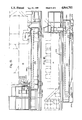
- FIG. 1 is a side elevational view illustrating the riveting apparatus of the present invention operating on a workpiece in the form of a major subassembly held in a fixture;
- FIG. 2 is a plan view of the riveting apparatus and fixture of FIG. 1;
- FIG. 3 is an end elevational view of the riveting apparatus and fixture of FIG. 1;
- FIG. 4 is an end elevational view of the riveting apparatus of the present invention.
- FIG. 5 is a top plan view of the apparatus of FIG. 4;
- FIG. 6 is a side elevational view of the apparatus of FIG. 4;
- FIG. 7 is a view similar to FIG. 5 with parts removed and illustrating mechanisms for moving the positioning about axes perpendicular to the supporting surface;
- FIG. 8 is a side elevational view taken about on line 8--8 in FIG. 11;
- FIG. 9 is a sectional view taken about on line 9--9 in FIG. 8;
- FIG. 10 is a sectional view taken about on line 10--10 in FIG. 8;
- FIG. 11 is a fragmentary elevational view of an arrangement including a former board for holding the stringers in place against the wing skin during a riveting operation of the type shown in FIG. 1;
- FIG. 12 is a fragmentary elevational view of an arrangement including a former board and strongback for holding the stringers and wing skin in the fixture during riveting;
- FIG. 13 is a plan diagrammatic view illustrating an arrangement for transferring the riveting apparatus of the present invention between rows of vertically disposed workpieces for operation thereon;
- FIG. 14 is an elevational view, partly in section, taken about on lines 14-14 in FIG. 13;
- FIG. 15 is an elevational view similar to FIG. 4 showing a portion of the riveting apparatus and illustrating in side elevation a transfer vehicle for use in the arrangement of FIG. 13;
- FIG. 16 is a side elevational view thereof of the transfer vehicle of FIG. 15 as it would appear in carrying the riveting apparatus.
- riveting apparatus 10 for operation on a workpiece, generally designated 12, having opposite sides and supported on a surface generally designated 14 with the workpiece sides disposed substantially perpendicular to the supporting surface.
- surface 14 is the floor of a building such as a factory.
- workpiece 12 comprises a contoured wing panel rigidly held vertically in a fixture wherein a series of closely-spaced, horizontally disposed stringers are to be riveted to the wing panel.
- the wing panel includes a wing skin designated 16 which typically comprises a series of sections initially joined together in a suitable manner to provide a workpiece of significant length.
- the stringers designated 18 are in closely-spaced horizontal relation and held in place prior to riveting the wing skin by a series of vertically spaced formers 20 in a manner which will be described.
- the arrangement of wing skin 16, stringers 18 and formers 20 is held in a fixtures generally designated 24 in a manner so as to be disposed vertically, i.e. such that the opposite sides of the workpiece are substantially perpendicular to supporting surface 14.
- the fixture 24 comprises a lower frame member or beam 26 disposed substantially parallel to supporting surfaces 14, an upper frame or beam 28 in spaced, substantially parallel relation to frame 26, and a pair of end frame members 30 and 32.
- the opposite ends of fixture 24 are supported on surface 14 by screw jack leveling positioners 34 to provide three leveling points on the fixture.
- fixture 24 also is supported intermediate the ends thereof at spaced locations by alignment support and correction mechanisms in the form of hydraulic screw jacks 36.
- Each of the retractable supports 36 can be lowered, i.e. moved away from fixture frame 26 toward surface 14, to provide clearance for travel of riveting machine 10 along the workpiece in a manner which will be described.
- a preferred form of supports includes an hydraulic cylinder 37 disposed vertically in pit 38 extending below surface 14.
- the workpiece is held in fixture 24 by the master tooled header assembly 40 near end 32, by the support members generally designated 44 near end 30, and by a series of V-block type clamps or holders 46 at spaced locations between the lower and upper frames 26 and 28, respectively, and the adjacent edges of the workpiece 12.
- Header 40 is made from a master tool so that it will fit its opposite header, i.e. to insure that lefthand and righthand counterparts of bulky parts such as wing parts fit together.
- a laser attitude control for horizontal/vertical alignment of fixture 24 and workpiece 12 comprises a laser light source 50 on frame 26 and a sensor 52 on frame 28, the light path therebetween indicated by the broken line 54.
- Machine 10 comprises a frame having spaced-apart sides and adapted to move along workpiece 12 in a manner such that the sides of the frame straddle the workpiece 12.
- the machine sides are perpendicular to supporting surface 14 and parallel to the sides of workpiece 12.
- One of the sides of machine 10 is defined by a pair of upright, spaced and parallel columns, 58 and 60 shown in FIG. 1.
- the opposite side of the machine frame is defined by a pair of spaced apart upright and parallel columns 62,64.
- the machine frame includes a top 66 disposed parallel to supporting surface 14 for joining the frame sides, in particular, the columns 58,60,62 and 64 at the upper ends thereof as viewed in FIGS. 1-3.
- the machine frame also includes a base or bottom 68 disposed parallel to and located near supporting surface 14 and supporting the columns 58, 60, 62 and 64 at the lower ends thereof.
- the riveting machine frame is adapted to move along track means on supporting surface 14 and extending along workpiece 12.
- wheels for example, two of which wheels designated 74,76 in FIG. 1, which are rotatably connected in a suitable manner to base 68 and engage the rails 70, 72.
- One wheel can be sprung hydraulically so that all four wheels carry an equal load even though the tracks may be slightly misaligned in elevation, i.e. in the verical direction as viewed in FIGS. 1 and 3.
- Machine 10 can be driven along rails 70,72 by means of a driven pinion on machine 10 engaging a rack on a rail in a manner which will be described in more detail presently. Alternatively, the wheels may be driven.
- the riveting machine 10 of the present invention further comprises first and second carriage means 84 and 86, respectively, movably mounted on respective sides of the machine frame.
- Carrages 84,86 are movable toward and away from supporting surface 14 in directions parallel to the sides of the machine frame in a manner which will be described. This direction is substantially perpendicular to the above-described direction of movement of machine 10 along the tracks.
- the carriages 84 and 86 support and carry first and second positioners 88 and 89, respectively, which in turn support and carry first and second block means or head means 90 and 92, respectively.
- the heads 90,92 in turn, carry drilling and riveting tools for operation on workpiece 12 and are movable relative to the respective carriages 84,86 and positioners 88,89 in a manner which will be described.
- the machine 10 also is provided with platforms 96 and 98 which extend out from the opposite sides for carrying other components of the machine.
- platform 96 carries an air compressor 100, refrigerator-dryer 102 for treatment of the air and an hydraulic pump and fluid cooler 104.
- Platform 98 carries a hopper 106 for storing rivets and cabinet 108,110 for housing various controls.
- FIGS. 4-6 are enlarged views of the riveting machine 10 of FIGS. 1-3.
- the heads or blocks 90,92 carry riveting tools and related instrumentalities.
- a rivet bucking tool 116 is mounted on a fixed axis with respect to upset head 90 and is adapted to be reciprocated by an hydraulic cylinder 118. This axis is the central operating axis, i.e. the drilling and riveting axis of machine 10. Movement of bucking tool 116 is toward and away from the workpiece, i.e. along a path extending in a direction through the sides of the workpiece.
- the drill/buck/shave or head 92 carries, drilling, riveting and shaving tool assemblies.
- the tools can be carried on a transfer plate (not shown) adapted to be moved in a direction normal to the above-identified operational axis to selectively place the tools in alignment with that axis.
- the tool shown is a shaving tool 120 for smoothing the rivet heads after upset.
- a pressure foot bushing 124 also is carried by block 92 by means of spaced apart pneumatic cylinders 126,128.
- the bushing 124 is adapted to contact the workpiece around the location to be drilled and riveted, and the drilling and riveting tools move through a central opening in the bushing for contacting the workpiece.
- Movement of riveting machine 10 along tracks or rails 70,72 and 80 and hence along workpiece 12 in fixture 24 is provided in the present illustration by a rack and pinion drive.
- a gear box 130 carried by base 68 of the machine frame is driven by a servo motor 132.
- a pinion 134 on the output of gear box 130 meshes with a rack 136 on one of the rails, for example rail 72.
- the movement of machine 10 along the rails and along workpiece 12 is in a direction also designated the X axis. The exact location of machine 10 along the X axis is known at all times as derived from encoder feedback to the machine control. Alternatively, the wheels can be driven directly with periodic verification of position.
- Carriages 84, 86 are movable in opposite directions along paths perpendicular to the supporting surface 14. These paths are perpendicular to the X axis and are identified also as the Y axis. There is provided means on the carriage means 84,86 cooperating with means on the respective sides of the machine frame for moving carriages 84,86 in the foregoing manner.
- a pair of ball screws 140 and 142 are provided, one on each side of the machine frame and rotatably connected at opposite ends, for example, in brackets 144 and 146, respectively, fixed to frame top 66 and suitable means (not shown) adjacent frame bottom 68.
- Nut members 148 and 150 are threaded on screws 144 and 146, respectively, and engage extensions 152 and 154, respectively, on carriages 84 and 86, respectively.
- Each ball screw and nut assembly is driven by a right angle gear box powered by single servo motor, for example the drive indicated 158 in FIG. 6.
- the ball screw and nut assembly are matched and preloaded, and the carriages 84,86 are synchronously indexed along the Y axis, with encoder feedback to the machine control for monitoring the location.
- the arrangement also includes suitable means for counterbalancingthe weight. Movement of carriages 84,86 is guided by engagement between rollers 159 on carriages 84,86 which ride along tracks 160 on the frame columns.
- Machine 10 further comprises means for moving the frame in a transverse direction with respect to the workpiece to move the frame sides toward and away from the workpiece.
- the frame sides are movable in unison in this direction, which also is transverse to the direction of the rails 70,72 and which is designated the Z axis.
- the combination of columns 58, 60, 62 and 64 fixed to and depending from top 66 comprises a tied column structure. This structure is movably supported on the frame base or bottom 68 in the following manner.
- Columns 58, 60, 62 and 64 are provided with wheels 162, 164, 166 and 168, respectively, rotatably connected to the lower ends of the corresponding columns and contacting supporting surfaces on platforms in the form of slides 170, 172, 174 and 176, respectively, in frame base 68.
- the wheel axles are oriented to allow the above-identified transverse movement of the tied column structure.
- the structure is moved or indexed by a ball screw and nut assembly driven by a servo generally designated 180 in FIG. 4 wherein the ball screw is rotatably connected in frame base 68 and the nut member engages a surface of the tied column struhcture in a manner similar to that of the Y axis carriage drive.
- the nut member of Z axis drive 180 operatively engages the lower end of column 64. Similar Z axis drive arrangements can be provided adjacent to the lower ends of the other three columns.
- Machine 10 further comprises means on the first and second head means 90 and 92, respectively, co-operating with means on the first and second positioners 88 and 89, respectively, for moving the first and second head means 90,92 independently about axes substantially parallel to supporting surface 14 and the X axis.
- This direction is also designated the a axis and is normal to the plane of the paper as viewed in FIG. 4.
- each of heads 90,92 is pivotal about an axis, i.e. the a axis, generally parallel to the X axis. Movement of heads 90,92 is provided by rack and pinion drive arrangements in the heads and corresponding positioners. For example, as shown in FIG.
- an arcuate rack 184 on head 90 is in meshing engagement with a pinion 186 rotatably mounted on positioner 88 and driven by a motorized gearbox 188 on positioner 88. Movement of head 90,92 about the a axis in positioners 88,89 is guided by co-operative engagement between bearings 190 and arcuate tracks 192 on both of the respective components. Only the arrangement on head 90 is shown in FIG. 4 for convenience.
- the gearboxes for both head preferably are driven by servo motors which drive the gear segments within established travel limitations determined by appropriate sensors, and the a axis travel of each head 90,92 can be matched through axis calibration at the machine control.
- Machine 10 further comprises means on the first and second positioners 88 and 89, respectively, co-operating with means on the first and second carriage means 84 and 86, respectively, for moving the first and second positioners and with them the first and second head means independently about axes substantially perpendicular to supporting surface 14 and substantially parallel to the Y axis.
- This direction is also designated the b axis and is normal to the plane of the paper as viewed in FIG. 5.
- each of the positioners 88 and 89 and corresponding one of the heads 90,92 is pivotal about an axis, i.e. the b axis, generally parallel to the Y axis.
- the positioners 88 and 89, and therefore the heads 90 and 92, are supported by trunnions mounted within the carriage 84 and 86, respectively, and each positioner 88,89 is driven within the b axis travel limits by a d.c. servo motor and ballscrew and nut assembly.
- a servo motor 200 is held by a trunnion bracket 202 connected to a b axis support beam 203 fixed to carriage 86.
- a ball screw assembly 204 driven by motor 200 is operatively associated with a trunnion assembly 206 connected by a bracket 208 to positioner 89.
- positioner 88 and carriage 84 An identical arrangement of servo motor 200', trunnion bracket 202' , b axis support beam 203 ballscrew assembly 204', trunnion assembly 206', and bracket 208' is provided for positioner 88 and carriage 84.
- positioner 89 and carriage 86 For convenience, only the arrangement for positioner 89 and carriage 86 will be described in further detail, it being understood that the arrangement for positioner 88 and carriage 84 is identical in structure and operation.
- FIGS. 9 and 10 are enlarged views showing in further detail the operative relationship between ball screw assembly 204 and trunnion assembly 206.
- a nut member 210 on screw 204 has one end within trunnion assembly 206 and is housed within a ball nut guard 212.
- the end of screw 204 opposite motor 200 is supported within an arrangement of radial bearing 214 and bearing housing 216 which can be supported on carriage 86.
- Trunnion assembly 206 includes a trunnion plate 220 to which the end of nut 210 is fixed and through which screw 204 rotatably extends and a pair of diametrically opposed trunnion pins 222 and pin bushings 224 for mounting t5trunnion plate 220 within a trunnion ring 226.
- Rotation of screw 204 in either direction moves nut 210 to the left or right in FIG. 10 to pivot trunnion 206 and bracket to pivot positioner 89 and with it head 92 about the b axis.
- Movement of heads 90,92 about the b axis in carriages 84,86 is guided by co-operative engagement between bearings 234 and arcuate tracks 236 on the respective components. Movement of head 90,92 about the b axis can be under closed loop sensor control and the travel of each positioners 88,89 and with them head can be matched through axis calibration at the machine control.
- FIG. 11 illustrates in further detail one of the formers 20 in the arrangement of FIG. 1. It comprises an elongated board 240 having one side 242 curved to on conform to the surface of the workpiece, i.e. wing skins 16, and provided with a series of spaced notches or recesses 244 to receive stringers 18.
- the opposite side of board 240 can be straight.
- a clamp 246 secures skin 16 to board 240 at the upper end of the arrangement of FIG. 11 and a V-block member 248 further supports wing skin 16 at the lower end.
- FIG. 12 illustrates an alternative arrangement for use in some riveting applications wherein the combination of former board 240, wing skin 16 and stringers 18 is fastened to a strongback 254 which, in turn, is tightly held between upper and lower frames 28' and 26', respectively of a fixture.
- Strongback 254 is in the form of an elongated board having a curved side 256 confirming to the curvature of skin 16 and having a straight opposite side.
- former board 240 is connected to strongback 254 by suitable fasteners 258.
- the overall width of the arrangement of FIG. 12 is greater than that of FIG. 11 and is considered in providing the movement capability of machine 10 in the Z axis direction.
- Riveting machine 10 of the present invention operaes in the following manner.
- the machine 10 travels along workpiece 12 and fixture 24 in the X axis direction as shown in FIG. 1 to move successively to various locations on workpiece 12 to be drilled and riveted.
- the individual retractable supporting cylinders 36 move downward, one-by-one, to surface 14 or below if a recess is provided to allow riveter 10 to move to the next location.
- the particilar cylinder 36 rises to support the workpiece once again.
- carriages 84,86 are movable along he Y axis to reach additional locations to be drilled and riveted.
- the axis motions of machine 10 are as follows: X is travel along the wing span, Y is travel along the chord length, Z is travel to compensate for chord height, a is rotation about the X axis and b is rotation about the Y axis.
- the X, Y, Z, a and b motions allow machine 10 to align the riveting process normal to any point on the workpiece within an established work envelope.
- the X and Y axes can be programmable and addressable axes.
- the Z, a and b motions can be controlled by a closed loop normality sensor servo system which traces the aerodynamic surface of the workpiece.
- heads 90,92 can be mechanically geared together vertically through matched ball screws, matched right angle gear boxes and a single drive motor-gear-reducer-hydraulic counterbalance arrangement.
- a axis angle control can be through a simultaneous signal feed to two servo drives, each having an axis calibration supplied by the machine control so that slight deviation from the true position can be corrected.
- B axis angle control likewise can be through a second set of servo drives, again provided with axis calibration.
- the a and b axis originate at the work outer surface. The origins are held to that point by a Z axis movement sensor and associated servo motor and feedback loop. This is so that a minor deviation in the a or b attitude will have no effect on the X or Y position.
- Machine 10 can move along workpiece 12 in fixture 24 several ways to accommodate the presence of formers 20.
- machine 10 can move in the X direction for riveting up to a former, then in the Z direction around the former and then in the X direction for continued riveting up to the next former and so as along the workpiece 12.
- the machine 10 can return to allow riveting in its location as machine 10 proceeds in the return direction. After machine 10 rivets and proceeds away from the location of a removed former it is replaced.
- the removal and replacement of formers 20 can be done manually or automatically by machine, either under control of riveter 10 or in response to a central control.
- machine 10 can move in a forward X direction for riveting up to a former, move in the reverse X direction a small distance to allow removal of the former either manually or by machine, then proceed in the forward X direction to rivet in the location of the former and beyond whereupon the former is returned to its position.
- FIGS. 13 and 14 are diagrammatic views of a riveting system according to the present invention including a plurality of riveters identical to riveter 10 and a plurality of workpieces and fixtures similar to workpiece 12 and fixture 24.
- the workpiece and supporting fixtures are arranged in four spaced-apart, mutually parallel rows comprising a first set, and another, four spaced-apart, mutually parallel rows in longitudinal alignment with the first four rows and comprising a second set.
- the workpiece and corresponding fixtures are disposed perpendicular to, i.e. vertically, a supporting surface 14'.
- riveters 10a, 10b, 10c and 10d each of the type like riveter 10 of FIGS. 1-10 including a frame having a pair of spaced apart sides adapted to move along track means on the supporting surface extending along a workpiece in a manner such that the frame sides are in straddling relation to the workpiece and carry drilling and riveting tools that are movable toward and away from the workpiece.
- the eight workpieces 12a-12h can comprise the left wing rear lower skin, left wing rear upper skin, left wing front lower skin, left wing front upper skin, right wing rear lower skin, right wing rear upper skin, right wing front lower skin, and right wing front upper skin, respectively.
- the travel path for each riveter along each workpiece and fixture is defined by spaced-apart, parallel tracks 70a, 72a-70h, 72h.
- the tracks of aligned rows are also aligned i.e. tracks 70a,72a are in longitudinal alignment with tracks 70e,72e and so on through the entire arrangement.
- tracks 70a,72a are in longitudinal alignment with tracks 70e,72e and so on through the entire arrangement.
- tracks 70a,72a are in longitudinal alignment with tracks 70e,72e and so on through the entire arrangement.
- tracks of aligned or opposite rows are aligned, for example tracks 270a and 270e.
- riveters 10a-10d are located on the paths containing workpieces 12a-12d, respectively.
- the system of the present invention enables any riveter to be moved to any workpiece and fixture area in the arrangement of FIGS. 13 and 14 or to an out of service location for maintenance.
- shuttle carriage means adapted to receive and carry any riveter and movable along means defining a shuttle path extending in a direction transverse to and in communication with, i.e. intersecting, the workpiece paths.
- the riveter is received and carried by the shuttle carriage its orientation about the Y axis is not changed, and when the destination is reached the riveter simply can move off the carriage without changing position and is immediately ready for travel along the row where it is left by the shuttle carriage.
- the shuttle carriage means comprises a carriage 274 of welded steel construction which travels within a shallow pit 276 extending tranverse to track 70a,72a-72h, to any of the four interface locations shown in FIG. 13. For convenience, these four interface location are indicated by the representation of shuttle carriage 274 and riveter 10 shown in broken lines.
- Carriage 274 is supported by wheel track assemblies 280 of sufficient size to support the weight of the riveter and be electrically driven.
- rails 282,284 extend along the bottom of pit 276.
- the top 286 of shuttle carriage 274 is substantially flush with supporting surface 14 and is provided with track ashimblies 290,292 and a power trolley matching those utilized to facilitate riveter X axis travel.
- the tracks 290,292 are aligned with the tracks 70,72 at each intersection point allowing the riveter X axis drive to power directly onto the shuttle carriage 274.
- the carriage 274 has its own controller and operator. As shown in FIG. 13, pit 276 extends beyond the rows containing workpiece 12d, 12h to an out of service shunt location 296 for maintenance or storage. If desired, shunt side tracks at location 296 can be provided, extending perpendicular to pit 276, for temporary removal of a riveter from th shuttle carraige.
- one riveter can be taken out of service by moving it to the shunt section 296, and by replacement of a fixture in place with a workpiece, the appropriate riveter can be brought out of the shunt section and moved on line using the shuttle carriage 274 to move the riveter to the assembly area where used.
- the shuttle or traverse carriage 274 is used primarily to move riveters to and from assembly areas and to and from out of service or maintenance areas, when empty the shuttle carriage 274 can serve as a bridge over the shuttle or traverse pit 276.
- FIGS. 15 and 16 are enlarged views showing in further detail the shuttle or traverse carriage 274 and pit 276.
- on the top surface 286 of carriage 274 is provided with a pair of spaced apart rails 290,292 onto which a riveter 10 is moved and supported for conveyance by carriage 274 along the transverse path defined by pit 276.
- shuttle carriage is driven by a rack and pinion arrangement including a rack 300 on one of the tracks in pit 276, for example track 284, which is engaged by a pinion 302 driven by a motorized gear box 304 on carriage 274. Electric power is supplied by a rail 308.
- the shuttle carriage wheels can be driven directly.
- one of the four wheels providing movement of fastening machine 10 in the X direction is sprung by flexible supporting means, preferably fluid operated, so that the wheel carries its share of the load independent of vertical position over a short travel.
- flexible supporting means preferably fluid operated
- the wheel carries its share of the load independent of vertical position over a short travel For accurate placement of fasteners, it is of utmost importance that the two tracks along which machine 10 travels be parallel in both plan and elevation.
- one of the wheels, for example wheel 76 is hydraulically sprung so that all four wheels of machine 10 carry an equal load even though the tracks 70,72 may be slightly misaligned in elevation. Such vertical misalignment can occur over the large extent of surface 14 travelling along the length of the workpiece 12. As shown in FIG.
- the wheel bearing assembly and axle 310 are carried by block means 312 having a pair of arm-like side members joined by a web to provide a fork-like structure which rides up and down between gibs 314 which are fixed to be stationary with respect to the machine frame.
- the flexible supporting means is in the form of an hydraulic cylinder 316 the housing of which is fixed to the machine frame and the piston rod of which is connected to block means 312. Cylinder 316 is provided with controlled pressure to provide a maximum stroke in the vertical direction of about one-quarter inch.
Landscapes
- Engineering & Computer Science (AREA)
- Mechanical Engineering (AREA)
- Automatic Assembly (AREA)
Abstract
Description
Claims (7)
Priority Applications (3)
| Application Number | Priority Date | Filing Date | Title |
|---|---|---|---|
| US07/129,929 US4864702A (en) | 1985-06-14 | 1987-12-02 | Five axis riveter |
| US07/391,794 US4966323A (en) | 1987-12-02 | 1989-08-09 | Five axis riveter and system |
| US07/581,287 US5248074A (en) | 1987-12-02 | 1990-09-12 | Five axis riveter and system |
Applications Claiming Priority (2)
| Application Number | Priority Date | Filing Date | Title |
|---|---|---|---|
| US74525385A | 1985-06-14 | 1985-06-14 | |
| US07/129,929 US4864702A (en) | 1985-06-14 | 1987-12-02 | Five axis riveter |
Related Parent Applications (1)
| Application Number | Title | Priority Date | Filing Date |
|---|---|---|---|
| US74525385A Continuation-In-Part | 1985-06-14 | 1985-06-14 |
Related Child Applications (1)
| Application Number | Title | Priority Date | Filing Date |
|---|---|---|---|
| US07/391,794 Division US4966323A (en) | 1987-12-02 | 1989-08-09 | Five axis riveter and system |
Publications (1)
| Publication Number | Publication Date |
|---|---|
| US4864702A true US4864702A (en) | 1989-09-12 |
Family
ID=26828038
Family Applications (1)
| Application Number | Title | Priority Date | Filing Date |
|---|---|---|---|
| US07/129,929 Expired - Lifetime US4864702A (en) | 1985-06-14 | 1987-12-02 | Five axis riveter |
Country Status (1)
| Country | Link |
|---|---|
| US (1) | US4864702A (en) |
Cited By (26)
| Publication number | Priority date | Publication date | Assignee | Title |
|---|---|---|---|---|
| US4955119A (en) * | 1989-07-11 | 1990-09-11 | Imta | Multi-task end effector for robotic machining center |
| US5033174A (en) * | 1990-02-22 | 1991-07-23 | Zieve Peter B | Yoke assembly system for large scale mechanical assembly operations |
| US5060375A (en) * | 1989-04-21 | 1991-10-29 | Gec Alsthom Sa | Method and device for riveting a shroud to the tips of rotor blades |
| EP0483947A3 (en) * | 1990-10-29 | 1992-08-26 | Gemcor Engineering Corp. | Method and apparatus for positioning tooling |
| US5154643A (en) * | 1990-10-29 | 1992-10-13 | Gemcor Engineering Corporation | Method and apparatus for positioning tooling |
| US5201205A (en) * | 1991-09-16 | 1993-04-13 | Electroimpact, Inc. | Two axis tracer for fastener operations |
| US5357668A (en) * | 1993-06-29 | 1994-10-25 | Gemcor Engineering Corp. | Method and apparatus for positioning a workpiece and tooling |
| EP0620060A3 (en) * | 1993-04-14 | 1995-06-14 | Gen Electro Mech Corp | Method and apparatus for positioning tooling. |
| US5477596A (en) * | 1992-12-23 | 1995-12-26 | The Boeing Company | Stringer/clip placement and drilling |
| US5555616A (en) * | 1993-10-13 | 1996-09-17 | Gemcor Engineering Corporation | Method and apparatus for positioning of tooling efficiently |
| US5604974A (en) * | 1994-05-11 | 1997-02-25 | Gemcor Engineering Corporation | Apparatus for positioning a wing panel for riveting |
| US5611130A (en) * | 1993-06-28 | 1997-03-18 | Gemcor Engineering Corp. | Multi-position rotary head apparatus |
| US5699599A (en) * | 1996-04-04 | 1997-12-23 | Zieve; Peter B. | Multiple axis yoke for large scale workpiece assembly systems |
| WO1998009767A1 (en) * | 1996-09-09 | 1998-03-12 | General Electro Mechanical Corporation | Apparatus for actuating tooling |
| EP0836908A2 (en) | 1996-10-17 | 1998-04-22 | The Boeing Company | Wing panel assembly |
| US5896637A (en) * | 1996-09-25 | 1999-04-27 | Mcdonnell Douglas Corporation | Assembly tower |
| WO1999046079A1 (en) * | 1998-03-12 | 1999-09-16 | General Electro Mechanical Corporation | Flexible fixture system and method |
| US6029352A (en) * | 1997-09-25 | 2000-02-29 | The Boeing Company | Wing panel assembly |
| US6098260A (en) * | 1996-12-13 | 2000-08-08 | Mcdonnell Douglas Corporation | Rivet fastening system for radial fuselage joints |
| US6430796B1 (en) | 2000-05-03 | 2002-08-13 | The Boeing Company | Apparatus for performing automated manufacturing operations on panel-shaped workpieces |
| US6478722B1 (en) | 2000-02-18 | 2002-11-12 | The Boeing Company | C-frame assembly apparatus and method for large panel-shaped workpieces |
| US6550129B1 (en) | 2000-09-25 | 2003-04-22 | The Boeing Company | Portable computer numeric controlled manufacturing machines and associated methods |
| US20100011563A1 (en) * | 2008-06-12 | 2010-01-21 | Gemcor Ii, Llc | Flexible Fastening Machine Tool |
| US20160011593A1 (en) * | 2014-07-09 | 2016-01-14 | The Boeing Company | Mobile Platforms for Performing Operations Along an Exterior of a Fuselage Assembly |
| WO2019020228A1 (en) * | 2017-07-24 | 2019-01-31 | Broetje-Automation Gmbh | MACHINING SYSTEM FOR AIRCRAFT STRUCTURAL COMPONENTS |
| CN110125311A (en) * | 2018-12-12 | 2019-08-16 | 宋局 | A kind of new riveting automation equipment |
Citations (4)
| Publication number | Priority date | Publication date | Assignee | Title |
|---|---|---|---|---|
| BE495183A (en) * | ||||
| US3534896A (en) * | 1968-08-29 | 1970-10-20 | Gen Electro Mech Corp | Riveting machine |
| US3557442A (en) * | 1968-04-02 | 1971-01-26 | Gen Electro Mech Corp | Slug riveting method and apparatus |
| US4575289A (en) * | 1983-08-04 | 1986-03-11 | Carl Hurth Maschinen- Und Zahnradfabrik Gmbh & Co. | Apparatus for orienting the position of a machine tool carriage relative to a stationary machine part |
-
1987
- 1987-12-02 US US07/129,929 patent/US4864702A/en not_active Expired - Lifetime
Patent Citations (4)
| Publication number | Priority date | Publication date | Assignee | Title |
|---|---|---|---|---|
| BE495183A (en) * | ||||
| US3557442A (en) * | 1968-04-02 | 1971-01-26 | Gen Electro Mech Corp | Slug riveting method and apparatus |
| US3534896A (en) * | 1968-08-29 | 1970-10-20 | Gen Electro Mech Corp | Riveting machine |
| US4575289A (en) * | 1983-08-04 | 1986-03-11 | Carl Hurth Maschinen- Und Zahnradfabrik Gmbh & Co. | Apparatus for orienting the position of a machine tool carriage relative to a stationary machine part |
Cited By (63)
| Publication number | Priority date | Publication date | Assignee | Title |
|---|---|---|---|---|
| US5060375A (en) * | 1989-04-21 | 1991-10-29 | Gec Alsthom Sa | Method and device for riveting a shroud to the tips of rotor blades |
| US4955119A (en) * | 1989-07-11 | 1990-09-11 | Imta | Multi-task end effector for robotic machining center |
| US5033174A (en) * | 1990-02-22 | 1991-07-23 | Zieve Peter B | Yoke assembly system for large scale mechanical assembly operations |
| EP0483947A3 (en) * | 1990-10-29 | 1992-08-26 | Gemcor Engineering Corp. | Method and apparatus for positioning tooling |
| US5154643A (en) * | 1990-10-29 | 1992-10-13 | Gemcor Engineering Corporation | Method and apparatus for positioning tooling |
| US5201205A (en) * | 1991-09-16 | 1993-04-13 | Electroimpact, Inc. | Two axis tracer for fastener operations |
| US5477596A (en) * | 1992-12-23 | 1995-12-26 | The Boeing Company | Stringer/clip placement and drilling |
| US5661892A (en) * | 1993-04-14 | 1997-09-02 | Gemcor Engineering Corp. | Method for positioning tooling |
| EP0620060A3 (en) * | 1993-04-14 | 1995-06-14 | Gen Electro Mech Corp | Method and apparatus for positioning tooling. |
| US5477597A (en) * | 1993-04-14 | 1995-12-26 | Gemcor Engineering Corp. | Apparatus for positioning tooling |
| US5611130A (en) * | 1993-06-28 | 1997-03-18 | Gemcor Engineering Corp. | Multi-position rotary head apparatus |
| US5357668A (en) * | 1993-06-29 | 1994-10-25 | Gemcor Engineering Corp. | Method and apparatus for positioning a workpiece and tooling |
| US5555616A (en) * | 1993-10-13 | 1996-09-17 | Gemcor Engineering Corporation | Method and apparatus for positioning of tooling efficiently |
| US5687463A (en) * | 1993-10-13 | 1997-11-18 | Gemcor Engineering Corp. | Apparatus for positioning of tooling efficiently |
| US5604974A (en) * | 1994-05-11 | 1997-02-25 | Gemcor Engineering Corporation | Apparatus for positioning a wing panel for riveting |
| US5621970A (en) * | 1994-05-11 | 1997-04-22 | Gemcor Engineering Corp. | Method for positioning a wing panel for riveting |
| US5699599A (en) * | 1996-04-04 | 1997-12-23 | Zieve; Peter B. | Multiple axis yoke for large scale workpiece assembly systems |
| WO1998009767A1 (en) * | 1996-09-09 | 1998-03-12 | General Electro Mechanical Corporation | Apparatus for actuating tooling |
| US6357100B2 (en) | 1996-09-09 | 2002-03-19 | General Electro-Mechanical Corporation | Apparatus for actuating tooling |
| US5829115A (en) * | 1996-09-09 | 1998-11-03 | General Electro Mechanical Corp | Apparatus and method for actuating tooling |
| US5896637A (en) * | 1996-09-25 | 1999-04-27 | Mcdonnell Douglas Corporation | Assembly tower |
| EP0836908A2 (en) | 1996-10-17 | 1998-04-22 | The Boeing Company | Wing panel assembly |
| US6269527B1 (en) * | 1996-10-17 | 2001-08-07 | The Boeing Company | Wing panel assembly |
| EP0836908A3 (en) * | 1996-10-17 | 1998-10-28 | The Boeing Company | Wing panel assembly |
| US6098260A (en) * | 1996-12-13 | 2000-08-08 | Mcdonnell Douglas Corporation | Rivet fastening system for radial fuselage joints |
| US6029352A (en) * | 1997-09-25 | 2000-02-29 | The Boeing Company | Wing panel assembly |
| WO1999046079A1 (en) * | 1998-03-12 | 1999-09-16 | General Electro Mechanical Corporation | Flexible fixture system and method |
| US6478722B1 (en) | 2000-02-18 | 2002-11-12 | The Boeing Company | C-frame assembly apparatus and method for large panel-shaped workpieces |
| US6726610B2 (en) | 2000-02-18 | 2004-04-27 | The Boeing Company | C-frame assembly apparatus and method for large panel-shaped workpieces |
| US6430796B1 (en) | 2000-05-03 | 2002-08-13 | The Boeing Company | Apparatus for performing automated manufacturing operations on panel-shaped workpieces |
| US6550129B1 (en) | 2000-09-25 | 2003-04-22 | The Boeing Company | Portable computer numeric controlled manufacturing machines and associated methods |
| US20100011563A1 (en) * | 2008-06-12 | 2010-01-21 | Gemcor Ii, Llc | Flexible Fastening Machine Tool |
| US8220134B2 (en) | 2008-06-12 | 2012-07-17 | Gemcor Ii, Llc | Flexible fastening machine tool |
| US10525524B2 (en) | 2014-07-09 | 2020-01-07 | The Boeing Company | Dual-interface coupler |
| US10960458B2 (en) | 2014-07-09 | 2021-03-30 | The Boeing Company | Mobile platforms for performing operations inside a fuselage assembly |
| US9505051B2 (en) * | 2014-07-09 | 2016-11-29 | The Boeing Company | Mobile platforms for performing operations along an exterior of a fuselage assembly |
| US9782822B2 (en) | 2014-07-09 | 2017-10-10 | The Boeing Company | Wheel mounting system |
| US9895741B2 (en) | 2014-07-09 | 2018-02-20 | The Boeing Company | Utility fixture for creating a distributed utility network |
| US9937549B2 (en) | 2014-07-09 | 2018-04-10 | The Boeing Company | Two-stage riveting |
| US10016805B2 (en) | 2014-07-09 | 2018-07-10 | The Boeing Company | Mobile platforms for performing operations along an exterior of a fuselage assembly |
| US10046381B2 (en) | 2014-07-09 | 2018-08-14 | The Boeing Company | Metrology-based system for operating a flexible manufacturing system |
| US20180318911A1 (en) * | 2014-07-09 | 2018-11-08 | The Boeing Company | Mobile platforms for performing operations along an exterior of a fuselage assembly |
| USRE50861E1 (en) | 2014-07-09 | 2026-04-14 | The Boeing Company | Two-stage riveting |
| US10201847B2 (en) | 2014-07-09 | 2019-02-12 | The Boeing Company | Clamping feet for an end effector |
| US10213823B2 (en) | 2014-07-09 | 2019-02-26 | The Boeing Company | Autonomous flexible manufacturing system for building a fuselage |
| US12564874B2 (en) | 2014-07-09 | 2026-03-03 | The Boeing Company | Autonomous flexible manufacturing system for building a fuselage |
| US10406593B2 (en) | 2014-07-09 | 2019-09-10 | The Boeing Company | Method of using a tower for accessing an interior of a fuselage assembly |
| US20160009421A1 (en) * | 2014-07-09 | 2016-01-14 | The Boeing Company | Adjustable Retaining Structure for a Cradle Fixture |
| US20160011593A1 (en) * | 2014-07-09 | 2016-01-14 | The Boeing Company | Mobile Platforms for Performing Operations Along an Exterior of a Fuselage Assembly |
| US11203054B2 (en) | 2014-07-09 | 2021-12-21 | The Boeing Company | Clamping feet for an end effector |
| US10792728B2 (en) | 2014-07-09 | 2020-10-06 | The Boeing Company | Two-stage fastener installation |
| US10835947B2 (en) | 2014-07-09 | 2020-11-17 | The Boeing Company | Method for building an assembly fixture for supporting a fuselage assembly |
| US10835948B2 (en) * | 2014-07-09 | 2020-11-17 | The Boeing Company | Adjustable retaining structure for a cradle fixture |
| US10737316B2 (en) * | 2014-07-09 | 2020-08-11 | The Boeing Company | Mobile platforms for performing operations along an exterior of a fuselage assembly |
| US10974311B2 (en) | 2014-07-09 | 2021-04-13 | The Boeing Company | Metrology-based system for operating a flexible manufacturing system |
| US10744554B2 (en) | 2014-07-09 | 2020-08-18 | The Boeing Company | Utility fixture for creating a distributed utility network |
| US11235375B2 (en) | 2014-07-09 | 2022-02-01 | The Boeing Company | Dual-interface coupler |
| US11548057B2 (en) | 2014-07-09 | 2023-01-10 | The Boeing Company | Towers for accessing an interior of a fuselage assembly |
| US12290852B2 (en) | 2014-07-09 | 2025-05-06 | The Boeing Company | Autonomous flexible manufacturing system for building a fuselage |
| US11724305B2 (en) | 2014-07-09 | 2023-08-15 | The Boeing Company | Autonomous flexible manufacturing system for building a fuselage |
| US11565831B2 (en) | 2017-07-24 | 2023-01-31 | Broetje-Automation Gmbh | Machining system for aircraft structural components |
| WO2019020228A1 (en) * | 2017-07-24 | 2019-01-31 | Broetje-Automation Gmbh | MACHINING SYSTEM FOR AIRCRAFT STRUCTURAL COMPONENTS |
| CN110125311A (en) * | 2018-12-12 | 2019-08-16 | 宋局 | A kind of new riveting automation equipment |
Similar Documents
| Publication | Publication Date | Title |
|---|---|---|
| US4864702A (en) | Five axis riveter | |
| US4966323A (en) | Five axis riveter and system | |
| US4781517A (en) | Robotic automobile assembly | |
| US6449848B1 (en) | Flexible fixture method | |
| US5248074A (en) | Five axis riveter and system | |
| US8220134B2 (en) | Flexible fastening machine tool | |
| US6223413B1 (en) | Apparatus and method for positioning tooling | |
| CN110337349B (en) | Processing station | |
| US7055240B2 (en) | Positioning apparatus for precisely locating a part or other article | |
| CN109366068A (en) | Welding packing production line | |
| EP0836908B1 (en) | Wing panel assembly | |
| CN111069826A (en) | A steel structure automatic welding production line | |
| US7128195B2 (en) | Workpiece transfer system for stamping press | |
| CN110039331B (en) | Exchange workbench with standing function | |
| CN114473566A (en) | Machining system and machining method for front axle | |
| CN111482742B (en) | An automatic welding workstation for lifting scissor arms | |
| US4475863A (en) | Electric servo drive lift unit | |
| US20020100158A1 (en) | Method and system for efficient assembly of automotive components | |
| US3052140A (en) | Apparatus and method for manufacture of riveted plate girders | |
| CN112850154B (en) | A full-process automatic feeding and positioning device and method for longitudinal bones | |
| CN212239715U (en) | Welding workstation at bottom of elevator sedan-chair | |
| AU601059B2 (en) | Panelizing machine and method for use | |
| CN109357857B (en) | Car coupler coupling test system | |
| JP2708918B2 (en) | System for transferring workpieces through a series of processing stations | |
| CN113000895B (en) | Machine tool system for machining butt joint point holes of airplane wing bodies |
Legal Events
| Date | Code | Title | Description |
|---|---|---|---|
| AS | Assignment |
Owner name: GEMCOR ENGINEERING CORP., 785 HERTEL AVENUE BUFFAL Free format text: ASSIGNMENT OF ASSIGNORS INTEREST.;ASSIGNORS:SPELLER, THOMAS H.;DAVERN, JOHN W.;WEAVER, JEFFREY P.;AND OTHERS;REEL/FRAME:004897/0496 Effective date: 19871113 Owner name: GEMCOR ENGINEERING CORP.,NEW YORK Free format text: ASSIGNMENT OF ASSIGNORS INTEREST;ASSIGNORS:SPELLER, THOMAS H.;DAVERN, JOHN W.;WEAVER, JEFFREY P.;AND OTHERS;REEL/FRAME:004897/0496 Effective date: 19871113 |
|
| STCF | Information on status: patent grant |
Free format text: PATENTED CASE |
|
| FEPP | Fee payment procedure |
Free format text: PAYOR NUMBER ASSIGNED (ORIGINAL EVENT CODE: ASPN); ENTITY STATUS OF PATENT OWNER: SMALL ENTITY |
|
| FPAY | Fee payment |
Year of fee payment: 4 |
|
| FPAY | Fee payment |
Year of fee payment: 8 |
|
| REMI | Maintenance fee reminder mailed | ||
| FPAY | Fee payment |
Year of fee payment: 12 |
|
| SULP | Surcharge for late payment |
Year of fee payment: 11 |
|
| AS | Assignment |
Owner name: GEMCOR II, LLC, NEW YORK Free format text: ASSIGNMENT OF ASSIGNORS INTEREST;ASSIGNOR:GENERAL-ELECTRO MECHANICAL CORP.;REEL/FRAME:015676/0876 Effective date: 20040628 |