US4862683A - Apparatus for harvesting berries on low plants - Google Patents
Apparatus for harvesting berries on low plants Download PDFInfo
- Publication number
- US4862683A US4862683A US06/753,524 US75352485A US4862683A US 4862683 A US4862683 A US 4862683A US 75352485 A US75352485 A US 75352485A US 4862683 A US4862683 A US 4862683A
- Authority
- US
- United States
- Prior art keywords
- berries
- picking head
- reel
- tines
- ground
- Prior art date
- Legal status (The legal status is an assumption and is not a legal conclusion. Google has not performed a legal analysis and makes no representation as to the accuracy of the status listed.)
- Expired - Lifetime
Links
- 235000021028 berry Nutrition 0.000 title claims abstract description 82
- 238000003306 harvesting Methods 0.000 title claims abstract description 18
- 241000196324 Embryophyta Species 0.000 claims abstract description 29
- 240000000851 Vaccinium corymbosum Species 0.000 claims abstract description 12
- 235000003095 Vaccinium corymbosum Nutrition 0.000 claims abstract description 11
- 235000017537 Vaccinium myrtillus Nutrition 0.000 claims abstract description 11
- 235000021014 blueberries Nutrition 0.000 claims abstract description 11
- 230000033001 locomotion Effects 0.000 claims description 35
- 230000009471 action Effects 0.000 claims description 12
- 239000003381 stabilizer Substances 0.000 claims description 6
- 238000005096 rolling process Methods 0.000 claims description 4
- 230000002093 peripheral effect Effects 0.000 claims description 3
- 235000013399 edible fruits Nutrition 0.000 claims 1
- 230000007246 mechanism Effects 0.000 description 3
- 239000004743 Polypropylene Substances 0.000 description 2
- 238000004140 cleaning Methods 0.000 description 2
- 230000010006 flight Effects 0.000 description 2
- 239000000463 material Substances 0.000 description 2
- 230000004048 modification Effects 0.000 description 2
- 238000012986 modification Methods 0.000 description 2
- -1 polypropylene Polymers 0.000 description 2
- 229920001155 polypropylene Polymers 0.000 description 2
- 208000034656 Contusions Diseases 0.000 description 1
- 240000009088 Fragaria x ananassa Species 0.000 description 1
- 206010052428 Wound Diseases 0.000 description 1
- 208000027418 Wounds and injury Diseases 0.000 description 1
- 230000008859 change Effects 0.000 description 1
- 238000010276 construction Methods 0.000 description 1
- 230000008878 coupling Effects 0.000 description 1
- 238000010168 coupling process Methods 0.000 description 1
- 238000005859 coupling reaction Methods 0.000 description 1
- 230000008021 deposition Effects 0.000 description 1
- 230000009977 dual effect Effects 0.000 description 1
- 230000000694 effects Effects 0.000 description 1
- 239000002783 friction material Substances 0.000 description 1
- 239000010720 hydraulic oil Substances 0.000 description 1
- 230000006872 improvement Effects 0.000 description 1
- 239000002184 metal Substances 0.000 description 1
- 238000000034 method Methods 0.000 description 1
- 239000004033 plastic Substances 0.000 description 1
- 230000002028 premature Effects 0.000 description 1
- 230000009467 reduction Effects 0.000 description 1
- 230000004044 response Effects 0.000 description 1
- 235000021012 strawberries Nutrition 0.000 description 1
Images


Classifications
-
- A—HUMAN NECESSITIES
- A01—AGRICULTURE; FORESTRY; ANIMAL HUSBANDRY; HUNTING; TRAPPING; FISHING
- A01D—HARVESTING; MOWING
- A01D46/00—Picking of fruits, vegetables, hops, or the like; Devices for shaking trees or shrubs
-
- Y—GENERAL TAGGING OF NEW TECHNOLOGICAL DEVELOPMENTS; GENERAL TAGGING OF CROSS-SECTIONAL TECHNOLOGIES SPANNING OVER SEVERAL SECTIONS OF THE IPC; TECHNICAL SUBJECTS COVERED BY FORMER USPC CROSS-REFERENCE ART COLLECTIONS [XRACs] AND DIGESTS
- Y10—TECHNICAL SUBJECTS COVERED BY FORMER USPC
- Y10S—TECHNICAL SUBJECTS COVERED BY FORMER USPC CROSS-REFERENCE ART COLLECTIONS [XRACs] AND DIGESTS
- Y10S56/00—Harvesters
- Y10S56/10—Uneven terrain compensation
Definitions
- This invention relates to improved apparatus for harvesting crops such as berries on low plants and in particular is directed to apparatus for harvesting low bush (commonly known as wild) blueberries.
- a further object is to provide apparatus for efficiently picking low bush berries with a minimum of damage both to the plants and the berries.
- a further object is to provide harvesting apparatus which can be connected to and powered from a wide range of conventional farm tractors.
- a further object is to provide a harvester of the type described which is rugged and durable and at the same time reasonable in cost.
- the apparatus for harvesting berries on low plants as described in detail hereinafter typically comprises a picking head including a frame movable along the ground over the crop of berries in the path of travel.
- a reel is mounted on this frame for rotation about an axis transverse to the travel path.
- This reel includes a series of circumferentially spaced rows of tines capable of moving and engaging the berries to strip them from the plants.
- a cam arrangement is provided for moving the tines relative to the reel to facilitate the stripping action and to facilitate deposit of the stripped berries into the reel.
- a conveyor is provided to carry the berries which have been deposited into the reel outwardly of same and thence ultimately into a container.
- the above-noted frame is provided with special means for supporting the picking head on the ground for movement over same such that the picking head closely follows the contours of the ground.
- Special means are also provided for towing the picking head such that it is free to move upwardly or downwardly and to pitch and roll as the supporting means moves over irregularities on the ground surface.
- the picking head supporting means includes a pair of spaced apart skids which, in profile, include a smoothly convexly contoured frontal section emerging into more shallowly curved intermediate and rear sections. Extensive experimentation has shown that this arrangement allows the picking head and its picking reel to closely follow the irregularities on the ground surface thus assisting in providing for an efficient picking operation.
- the concept of towing the picking head, as opposed to pushing it, is also of importance and the towing means herein provided includes a bracket adapted to be fixed to a conventional tractor with a towing arm extending outwardly therefrom.
- a towing assembly is adapted to be interconnected between the arm and picking head and as is arranged to allow the previously noted motions of the picking head to take place during movement over the ground as it is towed alongside of the tractor.
- the towing assembly preferably comprises a towing yoke connected to the picking head to permit relative pitching motion between them about an axis transverse to the path of travel.
- the yoke is also connected to the towing arm to permit relative rolling motion and pivotal motion between them.
- the stabilizer bar may be also connected to the frame to prevent substantial lateral motion of the picking head relative to the tractor.
- a hoisting lever is arranged to be pivotally connected at an inner end of same to the tractor and a hydraulic ram is connected for raising and lowering the lever.
- Suitable means are provided for connecting the outer end of the lever to the picking head such that the picking head may be lifted up and lowered downwardly together with the lever.
- the above-noted connecting means e.g. a chain arrangement
- the above-noted connecting means is preferably arranged such that during lifting of the head upwardly, the frontal part of the picking head is initially lifted to cause the picking head and the skids thereon to rotate rearwardly thereby to assist same in clearing obstructions on the ground.
- the above-described harvesting apparatus incorporates a special conveyor for transporting the berries.
- the conveyor accordingly includes a belt consisting of a plurality of rigid sections or modules hinged together to form an endless flexible loop.
- Special sprockets are adapted to co-operate and engage with the belt sections to positively drive same in the endless path provided.
- Certain of these sections include flights to positively transport the berries.
- the above-noted cam means for moving the picking tines is shaped such that during reel rotation the tines open gradually while descending prior to engaging the plants so as to enter the plants with little disturbance and to thereafter close while retaining the berries stripped therefrom, the tines thereafter gradually opening as they ascend to continue to hold the berries therein; in particular, the cam is shaped to cause the tines to first close rapidly and to immediately thereafter open rapidly directly before the tines complete their ascent thereby to more efficiently release the berries from the tines and to deposit same on the conveyor.
- hydraulic motor means are provided for driving the reel and the conveyor means.
- the hydraulic motors together with suitable control valves readily enables the rotational speed of the reel to be adjusted relative to the rate of travel of the picking head along the ground thereby to optimize the stripping action. As described hereafter, the reel speed is adjusted so that each plant is raked a multiplicity of times in succession thereby to effectively remove the berries from same.
- a rotary brush is also arranged to rotate with its bristles in contact with a peripheral portion of the reel to clear debris from the tines.
- the hydraulic motor which drives the brush also serves to drive a section of the conveyor means which extends inside of the reel.
- FIG. 1 is a perspective view of the berry harvesting apparatus in accordance with the invention with the conventional farm tractor being shown in phantom;
- FIG. 2 is an exploded perspective view of the harvesting apparatus.
- FIG. 3 is a plan view thereof
- FIG. 4 is an elevation view of the inner end of the picking head
- FIG. 5 is a cross-section view of the picking head looking toward the outer end of the reel
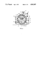
- FIG. 6 is a view similar to that of FIG. 5 but looking toward the opposite end of the picking reel;
- FIG. 7 is a longitudinal section view of the picking head
- FIG. 8 is a perspective view of the rear end of the conveyor assembly
- FIG. 9 illustrates the cam for moving the tines
- FIG. 10 is a view illustrating a portion of the conveyor belt and drive sprocket therefor.
- FIG. 11 is a fragmentary view of a tine bar and the manner of mounting same and;
- FIGS. 12 and 13 are opposite end views of a tine bar.
- FIG. 1 there is shown at Figures as an example of a harvester 10 according to the invention including a picking head 12 located alongside a conventional farm tractor 13. (shown in phantom).
- the picking head includes a frame 14 which is movable along the ground over the crop of berries in a path of travel given by the arrow T, such picking head including a reel 16 mounted on frame 14 for rotation about an axis transverse to the path of travel.
- Reel 16 is provided with a series of circumferentially spaced row of tines 18 adapted to move and to engage the blueberries to strip them from the plants.
- the picking head also includes a cam arrangement (to be described hereafter) for moving the tines 18 relative to the reel 16 to facilitate the stripping action and to facilitate deposit of berries into the reel.
- a primary conveyor arrangement 20 extending inside of the reel 16 serves to carry the berries outwardly of the reel and to deposit same into a secondary conveyor 22, the latter extending rearwardly and thence upwardly and outwardly of the rear end of the tractor.
- a horizontal platform 24 is mounted at the rear of the tractor and includes suitable brackets thereon for connection to the hydraulically activated tractor hitch points (not shown). This permits the platform to be raised or lowered.
- the platform 24 includes a raised subplatform 26 upon which suitable containers (not shown) may be positioned thereby to receive berries passing rearwardly, upwardly and thence outwardly on the secondary conveyor 22.
- the picking head frame 14 is provided with a laterally spaced apart pair of skids 28 which, during use, serve to support the picking head 12 directly on the ground for sliding movement thereover. Hence, during operation, the picking head 12 closely follows the contours of the ground.
- the harvesting apparatus also includes a mechanism 30 for towing the picking head 12 such that the picking head is free to move upwardly or downwardly and to pitch and roll as the spaced apart skids 28 move over irregularities on the ground surface. This freedom of the picking head to move in such a way as to closely follow the ground contour is most important to a successful picking operation.
- the above-noted towing mechanism 30 includes a bracket 32 adapted to be fixed to the front end of the tractor with a towing arm 34 extending laterally outwardly beyond the front wheel of the tractor.
- a towing yoke 36 is pivotally connected to the picking head 12 at spaced apart pivot points 38 which permit relative pitching motion between the yoke 36 and picking head 12 about a horizontal axis transverse to the path of travel.
- the front end of the yoke 36 is connected at a single point to the arm 34. This single point connection is provided by a forwardly extending stud 40 on the towing yoke which extends through aperture 42 provided in a bracket secured to the outer end of towing arm 34 with a suitable lock nut being secured on stud 40.
- a stabilizer bar 44 extends laterally below the mid point of the tractor to a bracket (not shown) located on the other side of the tractor to which the inner end 46 of the stabilizer bar is pivotally attached.
- the opposite end of stabilizer bar 46 is pivotally secured at pivot point 48 to the frontal end of the frame of the secondary conveyor 22 and also via a pivot member 50 to a pivot bracket located at the inner end of picking head 12.
- a hoisting lever 52 is pivotally connected at its inner end 54 to an upstanding bracket post 56 fixedly secured to the tractor. Also secured to post 56 is a reservoir tank 58 which holds the hydraulic oil for the lift system and hydraulic motors.
- the outer end 60 of hoisting lever 52 is connected via fore, and aft chains 62 and 64 respectively to front and rear portions respectively of the picking head 12 as best illustrated in FIG. 1.
- Intermediate portion of lever 52 is provided with a bracket 66 which is pivotally connected to hydraulic cylinder 68.
- the ram of the hydraulic cylinder is pivotally connected to bracket 70 secured firmly to the tractor.
- the fore and aft chains 62 and 64 are arranged such that as hoisting lever 52 is raised upwardly, the frontal portion of the picking head 12 is initially lifted so as to cause the picking head 12 and its supporting skids 28 to rotate rearwardly thereby to assist the skids in clearing obstructions on the ground. This can be easily achieved by adjusting the relative lengths of chains 62 and 64 i.e. by making chain 62 relatively shorter than chain 64.
- the profile shape or contour of the supporting skids 28 is best illustrated in FIG. 4. It will be noted that the frontal portion 72 of each skid is smoothly convexly contoured in a relatively pronounced manner. This frontal section 72 merges into a more shallowly convexly curved intermediate and rear section 73.
- the smoothly convexly curved contour arrangement of the skids 28 substantially prevents digging in of the front portions of the skids in rough terrain and at the same time encourages the to and fro pitching movement of the picking head 12 as humps and hollows in the terrain are encountered.
- the lower edges of skids 28 are each provided with a skid plate 74 of sufficient width as to prevent digging in of the skids during movement over the usual surfaces encountered during use and at the same time they prevent overly rapid wear of the skids during use.
- the farm tractor is equipped with a suitable commercially available hydraulic pump (not shown) which supplies, via flexible lines and suitable commercially available control valves (not shown) the hydraulic motors 80, 82 and 84.
- Hydraulic motors 80 and 82 are mounted on the outer end of the picking head frame 14 while hydraulic motor 84 is mounted to the rear end of the frame of the secondary conveyor 22.
- Motor 80 serves to drive reel 16 in rotation about its axis by way of a chain and sprocket drive to be described hereafter.
- Hydraulic motor 82 serves to drive elongated tine cleaning brush 86 in rotation about its axis, with the latter serving to drive, via gear reduction unit 88 on the inner end of picking head frame 14, the primary conveyor 20.
- the previously mentioned picking head frame 14 includes a spaced apart parallel pair of side plates 90 which are rigidly secured together in spaced apart relationship by transversely extending cross-frame members 92, 94 and 96 as shown in FIGS. 5 and 6 for example.
- Each of the previously described skids 28 is connected adjacent a lower edge of a respective side plate 90 with the frontal portion of each skid 28 being connected to side plate 90 via bolt 98 with a series of adjustment holes 100 being provided in each skid 28 to allow for a height adjustment to be made at the front end of the skid.
- the rear end of each skid 28 is connected to the frame 14 via cross-member 96 and a height adjustment device 102.
- Height adjustment device 102 is provided wit internal threads (not shown) such that when the upper end portion 104 of same is rotated by a suitable wrench, the support element 106 telescopes inwardly or outwardly of device 102 thus effecting a rear end height adjustment in a rapid and convenient manner.
- the reel 16 is rotatably mounted within frame 14, the reel 16 including opposed end plates 110 and 112 as best seen in FIGS. 5 and 6. Both end plates 110 and 112 have a circular outline and end plate 110 is journalled in hub 112 affixed to a frame side plate 90 (see FIG. 7).
- a short shaft section extending outwardly from the center of reel end plate 110 and through hub 113 has a drive sprocket 114 keyed thereto, such sprocket being driven in rotation by hydraulic motor 80 via sprocket 116 and roller-link drive chain 118.
- Hydraulic motor 80 is mounted on a bracket 120 secured to frame side plate 90 with the other hydraulic motor 82 also being mounted to an extension portion of that bracket.
- the primary conveyor 20 extends axially within the reel and outwardly through one end of same.
- the opposite reel end plate 112 must have an open center.
- a pair of rollers 124 journalled on suitable needle bearings, are mounted adjacent the lower edge of the frame side plate 90 associated with reel end plate 112. These rollers contact lower peripheral edge portions of the reel end plate thus securely supporting same during rotation of the reel 16.
- This same frame end plate 90 also has bolted to it a ring-like cam 126. This cam 126 serves to provide for opening and closing of the tines in a manner which will now be described more fully.
- each tine bar comprises a tubular member of generally rectangular cross-section as best seen in FIGS. 12 and 13, each tine bar being drilled at spaced intervals to receive the ends of the tines 18 which are then welded relative to their associated tine bars 128.
- Elongated tine bar support rod 130 extends through the center of each tine bar 128. The opposing ends of each support rod 130 are drilled and tapped to receive threaded studs 132, the latter passing through peripherally spaced apertures provided adjacent the outer peripheries of each of the reel end plates 110 and 112.
- peripherally spaced support rods 130 serve to rigidly secure the reel end plates 110 and 112 in their parallel spaced apart relationship while at the same time providing support for the tine bars 128 and also allowing the tine bars 128 to rotate thereon thus allowing the tine sets mounted to each tine bar to open and to close during rotation of reel 16 thereby to facilitate the berry stripping action etc.
- the tines 18 are spaced apart just sufficiently as to allow the berries to be stripped from the plants.
- a typical tine 18 as illustrated may have a total length in the order of 5 1/2" and a 5/16" diameter, with the outer portion of the tine bent at approximately a 45 degree angle to the shank of the tine. These tines are typically spaced along the tine bar 128 with a 17/32" center to center spacing. The tine tips are pointed as shown in FIGS. 12 and 13.
- Each tine bar 128 is provided with a cam follower as best shown in FIG. 13 comprising a bracket 134 to which is bolted a smoothly contoured follower body 136 made of a low-friction material such as ultra high molecular weight polypropylene.
- the opposite end of each tine bar is provided with a short lever 138 welded thereto and provided with short stud 140 at its outer end.
- each tine bar is provided with a cam follower 136 which closely engages the periphery of the previously noted cam 126 which is fixed relative to the frame end plate 90.
- the opposite reel end plate 110 is illustrated along with the peripherally spaced tine bars 128 each being provided adjacent the end of same with a short lever 138.
- the studs 141 at the outer ends of these levers each have a sturdy elastic, band 141 connected thereto, each elastic band 141 also passing around an associated pin 142 mounted in the plate 110.
- the strong elastic bands 141 serve to bias the cam followers 136 into close contacting relationship with the periphery of the ring-like cam 126. Therefore, as the reel 16 rotates in the direction of arrow P as shown in FIGS. 5 and 6, with the cam followers 136 in contact with the cam 126, the tine bars 128 are made to pivot about their respective support rods 130 in the predetermined cyclical fashion as determined by the shape or contour of cam 126 thereby causing the sets of tines on the respective tine bars 128 to open and close to facilitate the berry stripping action and to ensure that the stripped berries are conveyed upwardly and subsequently directed into the central portion of the reel onto the axially extending primary conveyor 20.
- FIG. 9 illustrates the shape of the ring-like cam 126.
- the direction of rotation of reel 16 relative thereto is given by the arrows P.
- the letters TDC and BDC represent the top dead center and bottom dead center positions respectively of the tines.
- the above-described tine bars 128 are peripherally spaced about a circle having a diameter of, for example, 20 inches.
- the harvester ground speed is typically in the order of 2 miles per hour.
- the reel 16 is driven by hydraulic motor 80 in an overspeed condition such that each blueberry plant is successively raked by a multiplicity of sets of tines e.g. each plant is preferably raked about three times over. This helps to ensure an effective and efficient stripping of the berries.
- the aforementioned cylindrical brush 86 rotates in contact with the tines 18 during the period of time that the closed tines are moving over the TDC position shown in FIG. 9.
- This brush is rotated by hydraulic motor 82 via chain and sprocket mechanism 83 at a speed of between 500 and 800 RPM.
- the shaft 150 of brush 86 is journalled adjacent its opposing ends in bearing blocks 152, the latter being mounted adjacent the upper edges of the frame end plates 90 in slotted guideways permitting shaft 150 to be adjusted upwardly or downwardly thereby to provide for the correct amount of brush to tine contact.
- the brush is provided with a 12" outside diameter and a 2" diameter core.
- the brush may of the spiral wound variety (such as is typically used in street cleaning equipment) and the bristles are typically of medium density polypropylene having a diameter of 0.060 inch.
- the right angle gear drive 88 includes a pulley 158 (see FIG. 4) which drives a further pulley 160 secured to shaft 162 journalled in the outer end of the frame of the primary conveyor 20.
- a spring biased idler pulley 164 holds the V-belt extending between pulleys 158 and 160 in tension, such V-belt being designated by reference 166.
- the same includes an elongated somewhat trough-like metal frame 170.
- the outer end of conveyor frame 170 is suspended from frame end plate 90 by way of a pair of support brackets 172 (see FIG. 4). Since the opposite end of conveyor frame 170 is located entirely within the rotating reel 16, special means must be provided for its support. Therefore, in order to accomplish this, the inner end wall 176 of the conveyor frame is provided with a bearing hub 178 within which is journalled a stub shaft 180 concentric with and mounted to the reel end plate 110 as best seen in FIGS. 5 and 7. Hence, by virtue of this arrangement, rotation of the reel 16 is permitted while at the same time the inner end of the conveyor frame 170 is securely supported by the stub shaft 180 located within bearing hub 178 attached to the end wall of the conveyor frame.
- tee conveyor frame 170 is provided with opposing side walls, the upper portions of which, designated 182, flare upwardly and outwardly into relatively close proximity to the circumferentially spaced apart tine bars 128.
- the outwardly flaring sidewall portions 182 are provided adjacent their extremities with flexible strip portions which come in very close proximity with the tine bars thus assisting in ensuring that all of the berries deposited into the reel in the manner described previously are captured by the primary conveyor.
- the primary conveyor 20 includes an outer drive shaft 162 journalled by a suitable bearings in the outermost end of the conveyor frame 170. Adjacent the opposite end of the conveyor frame there is provided a rotatable idler shaft 190. These shafts are each provided with an axially spaced apart pair of sprockets 192 which engage, an elongated endless conveyor belt 194 which is preferably of the type made by Intralox, Inc. of New La, U.S.A. A short segment of such belt is illustrated in FIG. 10 along with the sprocket 192.
- the belt is comprised of short modules of sections hinged together to provide the necessary degree of flexibility.
- every second section is provided with a flight 196 to positively engage and move the berries along the conveyor.
- the sprockets as shown in FIG. 10, are specially shaped so as to accommodate the modular design of the belt and the sprockets of course provide for positive drive of the belts.
- the sprockets have square bores which are mounted with some clearance on the square sectioned shafts thereby to allow axial movement of the sprockets in response to dimensional changes resulting from temperature fluctuations etc.
- the upper run of conveyor belt 194 is confined at its opposed marginal edges between elongated vertically spaced apart plastic strips 200 and 202 which are firmly attached to the opposing side walls of the conveyor frame 170.
- the opposing ends of the flights 196 on the belt are set inwardly from the marginal edges of the belt thereby to accommodate the guide strips 200, 202.
- the frame of the secondary conveyor 22 includes a horizontal section 204, an upwardly inclined section 206 and a short horizontally extending rear section 208.
- the hydraulic drive motor 84 is connected to this rear section 208 and rotates a shaft having sprockets thereon thereby to positively drive the secondary conveyor belt 210.
- the secondary conveyor belts, sprockets associated therewith, and the means for mounting the upper flight of such belt are all essentially as described previously in conjunction with the primary conveyor 20 and hence there is no need to repeat this description here.
- a small blower arrangement 216 is mounted just below the horizontal rear end section 208 of the secondary conveyor as illustrated in FIG. 8.
- This blower 216 is driven by a small electric motor 218 and is provided with a fan housing 220 enclosing a centrifugal fan, the output of which is directed through an outlet nozzle 222, the slot-like mouth 224 of which is located just below the extreme terminal end of the belt conveyor 210.
- the lighter leaves and other debris are carried away from the falling berries by virtue of the stream of air being emitted from the mouth of nozzle 222.
- the falling berries are deposited in containers of a convenient size (not shown) which are positioned on the subplatform 26 during operation.
- An operator positioned on main platform 24 positions the containers as desired and, when suitably filled, stacks them in convenient locations on platform 24.
- hoisting lever 52 When travelling to the picking site the previously described hoisting lever 52 is in the "up" position as also is the picking head 12 thereby allowing for easy transport to the picking area. When the picking area has been reached, hoisting lever 52 is lowered downwardly until the picking head is supported on the ground by way of the previously described skids 28. The several hydraulic motors, 80, 82 and 84 are activated so as to drive reel 16, brush 86 and the primary and secondary conveyors 20 and 22 in the manner described previously. The tractor is then put in its lowest gear and made to move forwardly at slow speed e.g. about 2 miles per hour, with the result being that a swath of berries is picked from the field.
- slow speed e.g. about 2 miles per hour
- the tractor follows the picked swath so as to avoid undue damage and crushing of the berries and the next adjacent swath is picked.
- the picking head is free to closely follow the contour of the terrain, and to pitch and roll and move upwardly and downwardly as required, thus ensuring that the reel 16 and picking tines 18 are in the desired close proximity to the ground during the picking operation. Since the rate of speed of the hydraulic motors may be closely controlled, variations can be made in the speed of reel rotation etc. thereby to optimize the picking operation.
Landscapes
- Life Sciences & Earth Sciences (AREA)
- Environmental Sciences (AREA)
- Harvester Elements (AREA)
- Harvesting Machines For Specific Crops (AREA)
Abstract
Description
Claims (23)
Priority Applications (1)
| Application Number | Priority Date | Filing Date | Title |
|---|---|---|---|
| US07/197,311 US5024052A (en) | 1985-07-09 | 1988-05-23 | Apparatus for harvesting berries on low plants |
Applications Claiming Priority (2)
| Application Number | Priority Date | Filing Date | Title |
|---|---|---|---|
| CA000486516A CA1249727A (en) | 1985-07-09 | 1985-07-09 | Blueberry harvester |
| CA486516 | 1985-07-09 |
Related Child Applications (1)
| Application Number | Title | Priority Date | Filing Date |
|---|---|---|---|
| US07/197,311 Continuation-In-Part US5024052A (en) | 1985-07-09 | 1988-05-23 | Apparatus for harvesting berries on low plants |
Publications (1)
| Publication Number | Publication Date |
|---|---|
| US4862683A true US4862683A (en) | 1989-09-05 |
Family
ID=4130955
Family Applications (1)
| Application Number | Title | Priority Date | Filing Date |
|---|---|---|---|
| US06/753,524 Expired - Lifetime US4862683A (en) | 1985-07-09 | 1985-07-10 | Apparatus for harvesting berries on low plants |
Country Status (2)
| Country | Link |
|---|---|
| US (1) | US4862683A (en) |
| CA (1) | CA1249727A (en) |
Cited By (7)
| Publication number | Priority date | Publication date | Assignee | Title |
|---|---|---|---|---|
| US6000203A (en) * | 1997-03-19 | 1999-12-14 | Weatherbee; Lloyd H. | Blueberry harvester |
| US20040123579A1 (en) * | 2002-12-11 | 2004-07-01 | Schutz A. James | Stick rake |
| US20080092507A1 (en) * | 2006-10-18 | 2008-04-24 | Dragotec Usa, Inc. | Corn head with tension control for deck plates |
| US20080236127A1 (en) * | 2007-03-28 | 2008-10-02 | Gerard Couture | Low-bush berry harvesting system and method |
| US9357707B1 (en) | 2015-02-27 | 2016-06-07 | Daniel Paulin | Method for harvesting a blueberry field |
| CN108668618A (en) * | 2018-07-28 | 2018-10-19 | 石河子大学 | A kind of comb clip safflower picker |
| US20190150362A1 (en) * | 2017-11-20 | 2019-05-23 | Deere & Company | Modular mounting system for a cotton harvester |
Families Citing this family (4)
| Publication number | Priority date | Publication date | Assignee | Title |
|---|---|---|---|---|
| US5375403A (en) * | 1993-10-28 | 1994-12-27 | Collins Border Holdings Ltd. | Lowbush berry harvester |
| US5369944A (en) * | 1993-12-13 | 1994-12-06 | Robichaud; Ora | Blueberry harvester and method of harvesting blueberries |
| CN113317038B (en) * | 2021-06-23 | 2022-12-13 | 广西师范大学 | Mulberry leaf combined picking machine |
| CN118923345A (en) * | 2024-08-28 | 2024-11-12 | 中国农业大学 | Height-adjustable strawberry picking robot |
Citations (50)
| Publication number | Priority date | Publication date | Assignee | Title |
|---|---|---|---|---|
| CA102113A (en) * | 1906-09-14 | 1906-11-20 | Harry Allan Peters | Berry picker |
| US1193189A (en) * | 1916-08-01 | richter | ||
| US1233089A (en) * | 1916-10-18 | 1917-07-10 | Cranberry Harvester Company | Cranberry-harvesting apparatus. |
| CA189690A (en) * | 1917-08-16 | 1919-04-15 | Horace B. Maglathin | Cranberry harvester |
| US1452629A (en) * | 1917-08-08 | 1923-04-24 | Peter Y Veeder | Berry-picking machine |
| US1622117A (en) * | 1920-07-23 | 1927-03-22 | Henry N Sweet | Berry-picking machine |
| US2220398A (en) * | 1940-03-18 | 1940-11-05 | Norbert A Dreikosen | Agricultural device |
| US2267879A (en) * | 1939-12-13 | 1941-12-30 | Ralph E Tillitt | Sugar beet loader |
| US2426545A (en) * | 1945-04-26 | 1947-08-26 | Syracuse Chilled Plow Co Inc | Potato digger and clutch therefor |
| CA522106A (en) * | 1956-02-28 | Mcdowell Fred | Berry picking machine | |
| CA523354A (en) * | 1956-04-03 | C. Getsinger Leonard | Cranberry harvesting machine | |
| CA609861A (en) * | 1960-12-06 | M. Furford Julius | Cranberry picking and pruning machine | |
| CA638778A (en) * | 1962-03-27 | Mcdowell Fred | Pneumatic berry stripper | |
| CA668287A (en) * | 1963-08-06 | Blueberry Equipment | Oscillating blueberry stripper | |
| CA672558A (en) * | 1963-10-22 | H. Tubbs Elton | Machine for harvesting berries | |
| US3130791A (en) * | 1963-02-04 | 1964-04-28 | Lloyd K Schmidt | Endless chain drive unit |
| US3165876A (en) * | 1963-01-16 | 1965-01-19 | Chisholm Ryder Co Inc | Bean picker |
| CA724370A (en) * | 1965-12-28 | M. Weygandt Raymond | Machine for harvesting berries and similar produce from their plants | |
| CA733269A (en) * | 1966-05-03 | Oeco Corporation | Moving carriage mechanical berry harvester with rotationally oscillative shakers | |
| US3252520A (en) * | 1961-10-31 | 1966-05-24 | Univ California | Tomato harvester |
| CA749625A (en) * | 1967-01-03 | Chisholm-Ryder Company | Bean picker | |
| CA764174A (en) * | 1967-08-01 | L. Towson Arthur | Bean picker | |
| CA778224A (en) * | 1968-02-13 | Mitchell Engineering Limited | Conveying apparatus | |
| CA783881A (en) * | 1968-04-30 | M. Weygandt Raymond | Apparatus for and method of harvesting berries and similar produce from bushes | |
| CA798585A (en) * | 1968-11-12 | D. Mohn Herbert | Berry picking machine | |
| CA811939A (en) * | 1969-05-06 | E. Pertics Emil | Berry picker | |
| US3473613A (en) * | 1967-04-26 | 1969-10-21 | Fmc Corp | Tomato harvester |
| CA828424A (en) * | 1969-12-02 | Holzmann Paul | Machine for picking berries and the like | |
| CA860596A (en) * | 1971-01-12 | W. Patzlaff Albert | Berry harvesting machine | |
| CA880628A (en) * | 1971-09-14 | Chisholm-Ryder Company | Grape harvesting machine | |
| US3616630A (en) * | 1969-10-10 | 1971-11-02 | Chisholm Ryder Co Inc | Machine for harvesting fruit on low plants |
| US3648447A (en) * | 1970-04-13 | 1972-03-14 | Chisholm Ryder Co Inc | Fruit harvesting machine for low plants |
| CA901817A (en) * | 1972-06-06 | Chisholm-Ryder Company | Bean harvester pick-up brush means | |
| CA916932A (en) * | 1972-12-19 | L. Holloway Robert | Fruit collector apparatus for harvesters | |
| CA942071A (en) * | 1971-08-26 | 1974-02-19 | Julius M. Furford | Cranberry harvesting apparatus |
| CA950685A (en) * | 1971-01-22 | 1974-07-09 | Virgil N. Jarrell | Multi-row, multi-crop harvester |
| CA959656A (en) * | 1971-07-13 | 1974-12-24 | Etablissement Public Dit: Agence Nationale De Valorisation De La Recherc He - A.N.V.A.R. | Harvesting machines |
| US3885375A (en) * | 1973-10-23 | 1975-05-27 | American Fine Foods Inc | Tractor mounted corn harvester |
| US3918239A (en) * | 1973-03-28 | 1975-11-11 | Ransomes Sims & Jefferies Ltd | Lawn mowers |
| CA988724A (en) * | 1972-04-10 | 1976-05-11 | Charles G. Burton | Picking arm construction in a machine for harvesting fruit grown of plants arranged in a row |
| CA1019960A (en) * | 1977-03-23 | 1977-11-01 | Michael H. Kuryluk | Rotary picker for harvesting fruit |
| CA1023634A (en) * | 1972-11-22 | 1978-01-03 | Dominic Ferraro | Viner |
| US4162606A (en) * | 1976-11-19 | 1979-07-31 | Ernst Weichel | Mower for mounting on the front end of an agricultural vehicle |
| CA1078192A (en) * | 1976-01-29 | 1980-05-27 | Charles L. Hecht | Air pickup system for mechanical strawberry pickers |
| CA1097086A (en) * | 1977-06-10 | 1981-03-10 | Walter Nedila | Device for use in picking berries |
| US4335570A (en) * | 1980-08-28 | 1982-06-22 | Fmc Corporation | Harvesting shaker for crops such as tomatoes or the like |
| US4343138A (en) * | 1979-06-19 | 1982-08-10 | Kuhn S.A. | Supporting structure for an agricultural machine |
| US4402175A (en) * | 1981-03-09 | 1983-09-06 | Patent Technology, Inc. | Pepper harvesting machine |
| US4464890A (en) * | 1981-12-10 | 1984-08-14 | Veb Kombinat Fortschritt Landmaschinen | Intake reel for agricultural machine |
| US4519191A (en) * | 1984-03-07 | 1985-05-28 | Board Of Trustees Of Michigan State Univ. | Strawberry harvester and procedures for growing and harvesting of such fruit |
-
1985
- 1985-07-09 CA CA000486516A patent/CA1249727A/en not_active Expired
- 1985-07-10 US US06/753,524 patent/US4862683A/en not_active Expired - Lifetime
Patent Citations (51)
| Publication number | Priority date | Publication date | Assignee | Title |
|---|---|---|---|---|
| CA798585A (en) * | 1968-11-12 | D. Mohn Herbert | Berry picking machine | |
| CA724370A (en) * | 1965-12-28 | M. Weygandt Raymond | Machine for harvesting berries and similar produce from their plants | |
| CA523354A (en) * | 1956-04-03 | C. Getsinger Leonard | Cranberry harvesting machine | |
| CA916932A (en) * | 1972-12-19 | L. Holloway Robert | Fruit collector apparatus for harvesters | |
| CA901817A (en) * | 1972-06-06 | Chisholm-Ryder Company | Bean harvester pick-up brush means | |
| CA880628A (en) * | 1971-09-14 | Chisholm-Ryder Company | Grape harvesting machine | |
| CA860596A (en) * | 1971-01-12 | W. Patzlaff Albert | Berry harvesting machine | |
| CA828424A (en) * | 1969-12-02 | Holzmann Paul | Machine for picking berries and the like | |
| US1193189A (en) * | 1916-08-01 | richter | ||
| CA609861A (en) * | 1960-12-06 | M. Furford Julius | Cranberry picking and pruning machine | |
| CA638778A (en) * | 1962-03-27 | Mcdowell Fred | Pneumatic berry stripper | |
| CA668287A (en) * | 1963-08-06 | Blueberry Equipment | Oscillating blueberry stripper | |
| CA672558A (en) * | 1963-10-22 | H. Tubbs Elton | Machine for harvesting berries | |
| CA811939A (en) * | 1969-05-06 | E. Pertics Emil | Berry picker | |
| CA522106A (en) * | 1956-02-28 | Mcdowell Fred | Berry picking machine | |
| CA783881A (en) * | 1968-04-30 | M. Weygandt Raymond | Apparatus for and method of harvesting berries and similar produce from bushes | |
| CA778224A (en) * | 1968-02-13 | Mitchell Engineering Limited | Conveying apparatus | |
| CA764174A (en) * | 1967-08-01 | L. Towson Arthur | Bean picker | |
| CA733269A (en) * | 1966-05-03 | Oeco Corporation | Moving carriage mechanical berry harvester with rotationally oscillative shakers | |
| CA749625A (en) * | 1967-01-03 | Chisholm-Ryder Company | Bean picker | |
| CA102113A (en) * | 1906-09-14 | 1906-11-20 | Harry Allan Peters | Berry picker |
| US1233089A (en) * | 1916-10-18 | 1917-07-10 | Cranberry Harvester Company | Cranberry-harvesting apparatus. |
| US1452629A (en) * | 1917-08-08 | 1923-04-24 | Peter Y Veeder | Berry-picking machine |
| CA189690A (en) * | 1917-08-16 | 1919-04-15 | Horace B. Maglathin | Cranberry harvester |
| US1622117A (en) * | 1920-07-23 | 1927-03-22 | Henry N Sweet | Berry-picking machine |
| US2267879A (en) * | 1939-12-13 | 1941-12-30 | Ralph E Tillitt | Sugar beet loader |
| US2220398A (en) * | 1940-03-18 | 1940-11-05 | Norbert A Dreikosen | Agricultural device |
| US2426545A (en) * | 1945-04-26 | 1947-08-26 | Syracuse Chilled Plow Co Inc | Potato digger and clutch therefor |
| US3252520A (en) * | 1961-10-31 | 1966-05-24 | Univ California | Tomato harvester |
| US3165876A (en) * | 1963-01-16 | 1965-01-19 | Chisholm Ryder Co Inc | Bean picker |
| US3130791A (en) * | 1963-02-04 | 1964-04-28 | Lloyd K Schmidt | Endless chain drive unit |
| US3473613A (en) * | 1967-04-26 | 1969-10-21 | Fmc Corp | Tomato harvester |
| US3616630A (en) * | 1969-10-10 | 1971-11-02 | Chisholm Ryder Co Inc | Machine for harvesting fruit on low plants |
| US3648447A (en) * | 1970-04-13 | 1972-03-14 | Chisholm Ryder Co Inc | Fruit harvesting machine for low plants |
| CA950685A (en) * | 1971-01-22 | 1974-07-09 | Virgil N. Jarrell | Multi-row, multi-crop harvester |
| CA959656A (en) * | 1971-07-13 | 1974-12-24 | Etablissement Public Dit: Agence Nationale De Valorisation De La Recherc He - A.N.V.A.R. | Harvesting machines |
| CA942071A (en) * | 1971-08-26 | 1974-02-19 | Julius M. Furford | Cranberry harvesting apparatus |
| CA988724A (en) * | 1972-04-10 | 1976-05-11 | Charles G. Burton | Picking arm construction in a machine for harvesting fruit grown of plants arranged in a row |
| CA1023634A (en) * | 1972-11-22 | 1978-01-03 | Dominic Ferraro | Viner |
| US3918239A (en) * | 1973-03-28 | 1975-11-11 | Ransomes Sims & Jefferies Ltd | Lawn mowers |
| US3885375A (en) * | 1973-10-23 | 1975-05-27 | American Fine Foods Inc | Tractor mounted corn harvester |
| CA1078192A (en) * | 1976-01-29 | 1980-05-27 | Charles L. Hecht | Air pickup system for mechanical strawberry pickers |
| US4162606A (en) * | 1976-11-19 | 1979-07-31 | Ernst Weichel | Mower for mounting on the front end of an agricultural vehicle |
| CA1019960A (en) * | 1977-03-23 | 1977-11-01 | Michael H. Kuryluk | Rotary picker for harvesting fruit |
| CA1097086A (en) * | 1977-06-10 | 1981-03-10 | Walter Nedila | Device for use in picking berries |
| US4343138A (en) * | 1979-06-19 | 1982-08-10 | Kuhn S.A. | Supporting structure for an agricultural machine |
| US4335570A (en) * | 1980-08-28 | 1982-06-22 | Fmc Corporation | Harvesting shaker for crops such as tomatoes or the like |
| US4335570B1 (en) * | 1980-08-28 | 1986-05-20 | ||
| US4402175A (en) * | 1981-03-09 | 1983-09-06 | Patent Technology, Inc. | Pepper harvesting machine |
| US4464890A (en) * | 1981-12-10 | 1984-08-14 | Veb Kombinat Fortschritt Landmaschinen | Intake reel for agricultural machine |
| US4519191A (en) * | 1984-03-07 | 1985-05-28 | Board Of Trustees Of Michigan State Univ. | Strawberry harvester and procedures for growing and harvesting of such fruit |
Cited By (8)
| Publication number | Priority date | Publication date | Assignee | Title |
|---|---|---|---|---|
| US6000203A (en) * | 1997-03-19 | 1999-12-14 | Weatherbee; Lloyd H. | Blueberry harvester |
| US20040123579A1 (en) * | 2002-12-11 | 2004-07-01 | Schutz A. James | Stick rake |
| US20080092507A1 (en) * | 2006-10-18 | 2008-04-24 | Dragotec Usa, Inc. | Corn head with tension control for deck plates |
| US20080236127A1 (en) * | 2007-03-28 | 2008-10-02 | Gerard Couture | Low-bush berry harvesting system and method |
| US9357707B1 (en) | 2015-02-27 | 2016-06-07 | Daniel Paulin | Method for harvesting a blueberry field |
| US20190150362A1 (en) * | 2017-11-20 | 2019-05-23 | Deere & Company | Modular mounting system for a cotton harvester |
| US10575466B2 (en) * | 2017-11-20 | 2020-03-03 | Deere & Company | Modular mounting system for a cotton harvester |
| CN108668618A (en) * | 2018-07-28 | 2018-10-19 | 石河子大学 | A kind of comb clip safflower picker |
Also Published As
| Publication number | Publication date |
|---|---|
| CA1249727A (en) | 1989-02-07 |
Similar Documents
| Publication | Publication Date | Title |
|---|---|---|
| US5024052A (en) | Apparatus for harvesting berries on low plants | |
| US4234045A (en) | Harvesting machine feeder apparatus | |
| US5287687A (en) | Harvesting apparatus | |
| US3698171A (en) | Mechanical picker for strawberries | |
| US6419093B2 (en) | Vegetable harvester | |
| NL8500009A (en) | CROP PROCESSING DEVICE. | |
| US9386749B1 (en) | Product to windrows pickup head | |
| US7555888B1 (en) | Pull type pepper harvester | |
| US4546602A (en) | Chili pepper harvester | |
| US5375403A (en) | Lowbush berry harvester | |
| US4862683A (en) | Apparatus for harvesting berries on low plants | |
| US6003293A (en) | Vegetable harvester | |
| US6557335B2 (en) | Mechanical harvester and continuous row harvesting method for use in overhead trellis systems | |
| US6000203A (en) | Blueberry harvester | |
| US5375402A (en) | Cranberry harvesting method and apparatus | |
| US20050210853A1 (en) | Pepper harvester | |
| CA2100204A1 (en) | Picking head for lowbush berry harvester | |
| US3456429A (en) | Sugarcane harvesting apparatus | |
| US5174093A (en) | Mechanized non-destructive crop harvesting machine | |
| US3992860A (en) | Towed tobacco harvester | |
| US4244165A (en) | Harvester apparatus | |
| US5709071A (en) | Chili harvester with adjustable spiral picker units | |
| US3712039A (en) | Crop pick-up harvester | |
| US3625291A (en) | Peanut-harvesting machine | |
| US3653194A (en) | Asparagus harvesting device |
Legal Events
| Date | Code | Title | Description |
|---|---|---|---|
| AS | Assignment |
Owner name: BRAGG LUMBER COMPANY LIMITED, COLLINGWOOD, N. S. B Free format text: ASSIGNMENT OF ASSIGNORS INTEREST.;ASSIGNORS:WEATHERBEE, H. LLOYD;BRAGG, DOUGLAS R.;WEATHERBEE, LLOYD H.;REEL/FRAME:004429/0602 Effective date: 19850708 |
|
| AS | Assignment |
Owner name: DOUG BRAGG ENTERPRISES LTD., COLLINGWOOD, N.S.BOM Free format text: ASSIGNMENT OF ASSIGNORS INTEREST.;ASSIGNOR:BRAGG LUMBER COMPANY LIMITED;REEL/FRAME:004823/0177 Effective date: 19880111 Owner name: DOUG BRAGG ENTERPRISES LTD.,CANADA Free format text: ASSIGNMENT OF ASSIGNORS INTEREST;ASSIGNOR:BRAGG LUMBER COMPANY LIMITED;REEL/FRAME:004823/0177 Effective date: 19880111 |
|
| STCF | Information on status: patent grant |
Free format text: PATENTED CASE |
|
| FEPP | Fee payment procedure |
Free format text: PAYOR NUMBER ASSIGNED (ORIGINAL EVENT CODE: ASPN); ENTITY STATUS OF PATENT OWNER: SMALL ENTITY |
|
| FPAY | Fee payment |
Year of fee payment: 4 |
|
| FEPP | Fee payment procedure |
Free format text: PAYER NUMBER DE-ASSIGNED (ORIGINAL EVENT CODE: RMPN); ENTITY STATUS OF PATENT OWNER: SMALL ENTITY |
|
| FPAY | Fee payment |
Year of fee payment: 8 |
|
| FEPP | Fee payment procedure |
Free format text: PAYOR NUMBER ASSIGNED (ORIGINAL EVENT CODE: ASPN); ENTITY STATUS OF PATENT OWNER: SMALL ENTITY |
|
| FPAY | Fee payment |
Year of fee payment: 12 |