US4860542A - Piston-cylinder pulsator circuit with superplastic alloy pressure transmitting medium - Google Patents

Piston-cylinder pulsator circuit with superplastic alloy pressure transmitting medium Download PDF

Info

Publication number
US4860542A
US4860542A US07/093,795 US9379587A US4860542A US 4860542 A US4860542 A US 4860542A US 9379587 A US9379587 A US 9379587A US 4860542 A US4860542 A US 4860542A
Authority
US
United States
Prior art keywords
piston
pressure
medium
force
pressure transmitting
Prior art date
Legal status (The legal status is an assumption and is not a legal conclusion. Google has not performed a legal analysis and makes no representation as to the accuracy of the status listed.)
Expired - Fee Related
Application number
US07/093,795
Inventor
Haruaki Hatayama
Hideo Takei
Takuji Okabe
Yoshiharu Waku
Toyoaki Ueno
Current Assignee (The listed assignees may be inaccurate. Google has not performed a legal analysis and makes no representation or warranty as to the accuracy of the list.)
Ube Corp
Original Assignee
Ube Industries Ltd
Priority date (The priority date is an assumption and is not a legal conclusion. Google has not performed a legal analysis and makes no representation as to the accuracy of the date listed.)
Filing date
Publication date
Application filed by Ube Industries Ltd filed Critical Ube Industries Ltd
Application granted granted Critical
Publication of US4860542A publication Critical patent/US4860542A/en
Anticipated expiration legal-status Critical
Expired - Fee Related legal-status Critical Current

Links

Images

Classifications

    • FMECHANICAL ENGINEERING; LIGHTING; HEATING; WEAPONS; BLASTING
    • F15FLUID-PRESSURE ACTUATORS; HYDRAULICS OR PNEUMATICS IN GENERAL
    • F15BSYSTEMS ACTING BY MEANS OF FLUIDS IN GENERAL; FLUID-PRESSURE ACTUATORS, e.g. SERVOMOTORS; DETAILS OF FLUID-PRESSURE SYSTEMS, NOT OTHERWISE PROVIDED FOR
    • F15B21/00Common features of fluid actuator systems; Fluid-pressure actuator systems or details thereof, not covered by any other group of this subclass
    • F15B21/06Use of special fluids, e.g. liquid metal; Special adaptations of fluid-pressure systems, or control of elements therefor, to the use of such fluids
    • YGENERAL TAGGING OF NEW TECHNOLOGICAL DEVELOPMENTS; GENERAL TAGGING OF CROSS-SECTIONAL TECHNOLOGIES SPANNING OVER SEVERAL SECTIONS OF THE IPC; TECHNICAL SUBJECTS COVERED BY FORMER USPC CROSS-REFERENCE ART COLLECTIONS [XRACs] AND DIGESTS
    • Y10TECHNICAL SUBJECTS COVERED BY FORMER USPC
    • Y10STECHNICAL SUBJECTS COVERED BY FORMER USPC CROSS-REFERENCE ART COLLECTIONS [XRACs] AND DIGESTS
    • Y10S72/00Metal deforming
    • Y10S72/709Superplastic material

Definitions

  • the present invention relates to a method and apparatus for transmitting a force utilizing a pressure transmitting medium.
  • a gas e.g., air
  • a liquid e.g., oil, water
  • IIP hot isostatic pressing
  • a liquid medium can generate a pressure higher than that generated by a gas medium, since a liquid has a compressibility much smaller than a gas.
  • oil such as inclusion of gas (air), decrease of its compressibility under a very high pressure condition, and an upper limit (up to 200° C.) of its service temperature.
  • an upper service temperature limit is determined since oil can burn when used at a high temperature.
  • the liquid and gas are apt to leak due to fluctuations in temperature and pressure, particularly under a high pressure condition, so that the sealing structure must be complicated. Still further, if part of the feeding system of the liquid or gas under pressure breaks, the liquid or gas will spout out from the broken part.
  • An object of the present invention is to provide a new material for a pressure transmitting medium.
  • Another object of the present invention is to provide a method for transmitting a force under a high temperature condition and/or a high pressure condition.
  • Still another object of the present invention is to provide an apparatus for performing the above-mentioned method.
  • the present invention is based on the fact that a superplastic alloy has a superior ability to transmit pressure.
  • pressure transmitting apparatuses utilizing liquids or gases, but no pressure transmitting apparatus utilizing metal as a medium has yet been developed. That is, the present inventors assume that persons skilled in the art have little idea that metal has an ability for transmitting pressure like a liquid.
  • FIG. 1 is a schematic sectional view of an apparatus for transmitting pressure according to the present invention
  • FIG. 2 is a graph showing a relationship between forces F 1 and F 2 and displacement of a small piston
  • FIG. 3 is a graph showing a relationship between an efficiency "Q" of pressure transmission and a velocity of a small piston
  • FIG. 5 is a graph similar to FIG. 4 at various ⁇ ;
  • FIG. 6a is a sectional view of a superplastic alloy medium
  • FIG. 6b is a schematic sectional view of another apparatus for transmitting pressure enclosing the medium shown in FIG. 6a, according to the present invention.
  • FIGS. 7 and 8 are graphs showing relationships between an applied force and an obtained force.
  • FIG. 9 is a schematic sectional view of a pressure transmitting apparatus for hot-press sintering according to the present invention.
  • an apparatus for transmitting pressure includes a cylinder 1, a piston 2 having a sectional area A 1 , a stationary piston guide 3 for the piston 2, a piston 4 having a sectional area A 2 , and a superplastic alloy medium 5.
  • the sectional area A 2 larger than the sectional area A 1 .
  • the superplastic alloy medium 5 is, e.g., Sn-38Pb (eutectic) and is placed between the piston guide 3 and the piston 4 within the cylinder 1.
  • Superplasticity indicates a phenomenon of extremely large elongation of metal under a low stress at a low strain rate. Generally, when a superplastic alloy is deformed under specific conditions, the alloy displays a remarkable elongation of more than 200%, occasionally more than 1000%.
  • An Sn-38Pb superplastic alloy medium was produced in the following manner.
  • Each of the obtained samples of the superplastic Sn-38Pb alloy was arranged in the above-mentioned pressure transmitting apparatus as shown in FIG. 1 and tested by applying a force F 1 on it (i.e., medium 5) through the piston 2 under various conditions.
  • the testing temperature (423° K.) was not varied.
  • FIGS. 2 to 5 The obtained data are shown in FIGS. 2 to 5.
  • " ⁇ " indicates a ratio of A 2 to A 1 (A 2 /A 1 ).
  • the relationship between the obtained force F 2 of the piston 4 and the force (i.e., load) F 1 of the piston 2 is indicated by the formula: ##EQU1## wherein: Q is an efficiency factor of pressure transmission (i.e., an evaluation factor of pressure transmission ability) of the Sn-38Pb medium 5.
  • the apparatus can serve as a force multiplication apparatus.
  • the temperature range enabling the superplastic alloy to act as a pressure transmitting medium and the elongation are dependent on the composition of the alloy. It is preferable that the superplastic alloy have an elongation of more than 300%.
  • the compression velocity i.e, a velocity of piston transfer
  • the strain rate sensitivity index "m" be more than 0.2, particularly, more than 0.3.
  • a vertical type apparatus for transmitting pressure comprises a cylinder 12, a small piston 13, a large piston 14, and a superplastic alloy medium 11 consisting of a body part having a diameter D of 50 mm and a projecting portion having a diameter d of 30 mm, and a height h of 10 mm.
  • the superplastic alloy medium 11 is made of Zn-22Al and is placed between the pistons 13 and 14 within the cylinder 12.
  • the Zn-22Al alloy medium was produced in the following manner:
  • Zn and Al were melted and cast into an ingot of eutectoid Zn-22Al having a diameter of 55 mm.
  • the ingot was homogenized by annealing it at a temperature of 653° K. (380° C.) for 7 days. Then, the ingot was machined to form the medium 11 (FIG. 6a) having the above-mentioned dimensions.
  • the medium 11 was heated at a temperature of 653° K. (380° C.) and was water-quenched so as to refine the alloy structure.
  • the obtained Zn-22Al medium was arranged in the apparatus as shown in FIG. 6b and was tested by applying to it a force (load) F 1 through the small piston 13 to investigate a relationship between the applied force F 1 and the obtained force F 2 through the large piston 14.
  • the testing temperature was 523° K. (250° C.) and the velocity of piston transfer was 1 mm/min (16.7 ⁇ 10 -6 m/s). Varying the period of application of the force F 1 , the results shown in FIGS. 7 and 8 were obtained.
  • the force F 2 is smaller than the force (load) F 1 .
  • the force F 1 of the piston 13 is sufficiently transmitted to the piston 14 through the medium 11, and the force F 2 , larger than the force F 1 , is attained.
  • the force F 1 is changed to zero (namely, application of the force F 1 is stopped)
  • the force F 2 does not become zero at once.
  • the force F 2 decreases fast to a certain point and then decreases gradually. In the course of the decrease of the force F 2 , if the force F 1 is reapplied on the piston 13, the force F 2 reincreases.
  • the superplastic alloy has the ability to transmit pressure.
  • the present invention utilizing the superplastic alloy as a pressure transmitting medium in an apparatus for transmitting pressure has the following advantages:
  • the apparatus can be used within a wide temperature range (from 0° C. to 2000° C.) by selecting a suitable superplastic alloy.
  • the apparatus can be used at a high temperature of, e.g., more than 200° C.
  • the superplastic alloy medium does not leak, unlike a liquid or gas, so that the sealing structure can be simplified.
  • the apparatus can be used under a high pressure condition.
  • the superplastic alloy medium is not compressed nor includes gas, unlike oil.
  • the method and apparatus according to the present invention can be applied to an HIP apparatus, an extruder for metal, a sintering apparatus for ceramic powder and metal powder by a hot press method, and various apparatuses for transmitting pressure.
  • a pressure transmitting apparatus for hot-press sintering comprises a container 21 with a lid 22, a piston 23, a superplastic alloy medium of two separate parts 24a and 24b, and heaters 25a, 25b, and 25c.
  • a powder body 26 of metal powder, ceramic powder, or metal powder and fiber for fiber reinforced metal (FRM) is sandwiched with the separate parts 24a and 24b so as to arrange it within the superplastic alloy medium. Then the superplastic medium 24a, 24b is placed in the container 21 and the lid 22 is fixed on the container 21.
  • the superplastic alloy medium containing the powder body 26 is heated by the heaters 25a-25c and is subjected to a force (load) F through the piston 23 actuated by, e.g., hydraulic power. While the sintering temperature for the powder body 26 is attained, the force F is applied so as to generate an isotactic compression pressure on the powder body. Thus the powder body is sintered under the pressure.

Landscapes

  • Engineering & Computer Science (AREA)
  • Chemical & Material Sciences (AREA)
  • Analytical Chemistry (AREA)
  • Physics & Mathematics (AREA)
  • Fluid Mechanics (AREA)
  • Mechanical Engineering (AREA)
  • General Engineering & Computer Science (AREA)
  • Press Drives And Press Lines (AREA)
  • Supply Devices, Intensifiers, Converters, And Telemotors (AREA)
  • Extrusion Of Metal (AREA)
  • Pistons, Piston Rings, And Cylinders (AREA)
  • Forging (AREA)

Abstract

In a method for transmitting force from one piston to another piston, a superplastic alloy is used between the pistons as a pressure transmitting medium. An apparatus adopting the method serves as a force multiplication apparatus.

Description

This is a division of application Ser. No. 816,201 filed Jan. 6, 1986 issued as U.S. Pat. No. 4,729,730 on Mar. 8, 1988.
BACKGROUND OF THE INVENTION
1. Field of the Invention
The present invention relates to a method and apparatus for transmitting a force utilizing a pressure transmitting medium.
2. Description of the Prior Art
A gas (e.g., air) or a liquid (e.g., oil, water) is conventionally used as a pressure transmitting medium in a pneumatic apparatus or a hydraulic apparatus. Such a pressure transmitting medium is also utilized by a hot isostatic pressing (IIP) apparatus, an extruder for metal, and the like used under high temperature operating conditions.
A liquid medium can generate a pressure higher than that generated by a gas medium, since a liquid has a compressibility much smaller than a gas. There are generally problems with oil, such as inclusion of gas (air), decrease of its compressibility under a very high pressure condition, and an upper limit (up to 200° C.) of its service temperature. Such an upper service temperature limit is determined since oil can burn when used at a high temperature. Furthermore, the liquid and gas are apt to leak due to fluctuations in temperature and pressure, particularly under a high pressure condition, so that the sealing structure must be complicated. Still further, if part of the feeding system of the liquid or gas under pressure breaks, the liquid or gas will spout out from the broken part.
SUMMARY OF THE INVENTION
An object of the present invention is to provide a new material for a pressure transmitting medium.
Another object of the present invention is to provide a method for transmitting a force under a high temperature condition and/or a high pressure condition.
Still another object of the present invention is to provide an apparatus for performing the above-mentioned method.
These and other objects of the present invention are attained by a method for transmitting a force by means of a pressure transmitting medium wherein a superplastic alloy is used as the medium.
The present invention is based on the fact that a superplastic alloy has a superior ability to transmit pressure. There are well-known pressure transmitting apparatuses utilizing liquids or gases, but no pressure transmitting apparatus utilizing metal as a medium has yet been developed. That is, the present inventors assume that persons skilled in the art have little idea that metal has an ability for transmitting pressure like a liquid.
BRIEF DESCRIPTION OF THE DRAWINGS
The present invention will become more apparent from the description of the preferred embodiments set forth below, with reference to the accompanying drawings, wherein:
FIG. 1 is a schematic sectional view of an apparatus for transmitting pressure according to the present invention;
FIG. 2 is a graph showing a relationship between forces F1 and F2 and displacement of a small piston;
FIG. 3 is a graph showing a relationship between an efficiency "Q" of pressure transmission and a velocity of a small piston;
FIG. 4 is a graph showing a relationship between the efficiency "Q" and a train rate sensitivity index "m", at α=10.2;
FIG. 5 is a graph similar to FIG. 4 at various α;
FIG. 6a is a sectional view of a superplastic alloy medium;
FIG. 6b is a schematic sectional view of another apparatus for transmitting pressure enclosing the medium shown in FIG. 6a, according to the present invention;
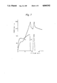
FIGS. 7 and 8 are graphs showing relationships between an applied force and an obtained force; and
FIG. 9 is a schematic sectional view of a pressure transmitting apparatus for hot-press sintering according to the present invention.
DESCRIPTION OF THE PREFERRED EMBODIMENTS
Referring to FIG. 1, an apparatus for transmitting pressure according to the present invention includes a cylinder 1, a piston 2 having a sectional area A1, a stationary piston guide 3 for the piston 2, a piston 4 having a sectional area A2, and a superplastic alloy medium 5. In this case, the sectional area A2 larger than the sectional area A1. The superplastic alloy medium 5 is, e.g., Sn-38Pb (eutectic) and is placed between the piston guide 3 and the piston 4 within the cylinder 1.
"Superplasticity" indicates a phenomenon of extremely large elongation of metal under a low stress at a low strain rate. Generally, when a superplastic alloy is deformed under specific conditions, the alloy displays a remarkable elongation of more than 200%, occasionally more than 1000%.
An Sn-38Pb superplastic alloy medium was produced in the following manner.
Sn and Pb were melted and cast into an ingot of Sn-38% Pb having a diameter of 55 mm and a length of 240 mm. The ingot was homogenized by annealing it at a temperature of 423° K. (150° C.) for 7 days. Then, the ingot was machined to form billets having a diameter of 50 mm and a length of 50 mm. The billets were extruded at a temperature of 373° K. (100° C.) into bars having diameters of 10 and 27 mm. Bars of 10 mm diameter were machined and then forged by using a die with a throughhole having a diameter of 16 mm at room temperature to form samples for a pressure transmitting medium. Bars of 27 mm were machined to form other samples having diameters of 25.4 mm.
Each of the obtained samples of the superplastic Sn-38Pb alloy was arranged in the above-mentioned pressure transmitting apparatus as shown in FIG. 1 and tested by applying a force F1 on it (i.e., medium 5) through the piston 2 under various conditions. The testing temperature (423° K.) was not varied.
The parameters of the testing conditions were as follows:
______________________________________                                    
Sample (medium 5) Diameter:                                               
                    16, 25.4, 50 mm                                       
Length (H):         5, 10, 30, 50 mm                                      
Area (A.sub.1) of Piston 2:                                               
                    19.6, 50.2, 176.7 mm.sup.2                            
Area (A.sub.2) of Piston 4:                                               
                    201, 506.7, 1964 mm.sup.2                             
Velocity (V) of Piston 2:                                                 
                    8.33 × 10.sup.-4 (m/s)                          
                    1.67 × 10.sup.-4                                
                    8.33 × 10.sup.-5                                
                    8.33 × 10.sup.-6                                
                    1.67 × 10.sup.-6                                
______________________________________                                    
The obtained data are shown in FIGS. 2 to 5. In FIGS. 2 to 5, "α" indicates a ratio of A2 to A1 (A2 /A1). The relationship between the obtained force F2 of the piston 4 and the force (i.e., load) F1 of the piston 2 is indicated by the formula: ##EQU1## wherein: Q is an efficiency factor of pressure transmission (i.e., an evaluation factor of pressure transmission ability) of the Sn-38Pb medium 5.
As shown in FIG. 2, as the displacement of the piston 2 increases, the forces F1 and F2 increase. The obtained force F2 of the large piston 4 is larger than the force (load) F1 of the small piston 2. Therefore, it is apparent that the Sn-38Pb (superplastic alloy) medium has an ability to transmit pressure.
If the medium is a liquid instead of a superplastic alloy, in accordance with Pascal's principle, the following formula is obtained:
F.sub.2 =(A.sub.2 /A.sub.1)F.sub.1
In this case, "Q" equals "1" (α=1). However, in the case of the Sn-38Pb (superplastic alloy) medium, another pressure transmission efficiency Q is obtained, which efficiency depends upon the velocity of the small piston, the strain rate sensitivity index (m), and the ratio of area, as shown in FIGS. 3, 4, and 5. The strain rate sensitivity index (m) is defined in relation to a certain strain rate. In FIGS. 3, 4 and 5, a strain rate of a portion of the sample adjoining the small piston 2 is considered as the strain rate of Sn-38pb sample. As the velocity (V) of the small piston decreases and as the strain rate sensitivity index (m) approaches its maximum value (about 0.68), the efficiency factor Q increases. A Q of 0.85 can be attained under the conditions: α=11.1, A1 =176.7 mm2, A2 =1964 mm2, H=10 mm, T=423° K., V=1.67×10⁻⁶ m/s, and m=0.68, as shown in FIG. 3. It is possible to obtain a Q of 0.93 at α=2.9 (FIG. 5). The apparatus can serve as a force multiplication apparatus.
It is possible to use superplastic alloys shown in Tables 1(a), 1(b) and 1(c) as the pressure transmitting medium.
                                  TABLE 1                                 
__________________________________________________________________________
                      Temperature                                         
                      range for                                           
                      pressure     Maximum                                
   Composition of     transmission                                        
                             Maximum                                      
                                   elongation                             
No.                                                                       
   superplastic alloy ability ° C.                                 
                             m     %                                      
__________________________________________________________________________
(a)                                                                       
1  Al--17% Cu         350-548                                             
                             0.7   600                                    
2  Al--37% Cu (eutectic)                                                  
                      "      0.8   500                                    
3  Al--33% Cu7% Mg    350-500                                             
                             0.72  >600                                   
4  Al--25% Cu--11% Mg "      0.69  >600                                   
5  Al--5.6% Zn--1.56% Mg--0.41% Zr                                        
                      350-600                                             
                             0.7   500                                    
6  Al--10.72% Zn--0.93% Mg--0.42% Zr                                      
                      350-600                                             
                             0.9   1550                                   
7  Bi--34% In (eutectic)                                                  
                      0-72   0.76  450                                    
8  Cd--27% Zn         0-260  0.5   350                                    
9  Co--10% Al         950-1300                                            
                             0.47  850                                    
10 Cu--9.8% Al        565-850                                             
                             0.7   700                                    
11 Cu--2.8% Al--1.8% Si--0.4% Co                                          
                      350-577                                             
                             0.46  318                                    
12 Cu--7% P           350-710                                             
                             0.5   >600                                   
13 Cu--38.5% Zn--3% Fe                                                    
                      454-900                                             
                             0.53  330                                    
14 Cu--40% Zn         454-850                                             
                             0.64  515                                    
15 Cu--28% Ag (eutectic)                                                  
                      500-779                                             
                             0.53  500                                    
16 A.I.S.I. 1340 Steel                                                    
                      720-910                                             
                             0.65  380                                    
17 0.18 C, 1.54 Mn, 0.01 Si,                                              
                      720-910                                             
                             0.55  320                                    
   0.9 P, 0.05 Al, 0.11 V                                                 
18 0.18 C, 1.54 Mn, 0.011 Si,                                             
                      "      0.55  376                                    
   1.98 P, 0.051 Al, 0.13 V                                               
19 Fe--4% Ni          900-1350                                            
                             0.58  820                                    
20 3% Mo, 1.6% Ti     930-1300                                            
                             0.67  615                                    
21 IN 744, Fe--6.5% Ni--26% Cr                                            
                      850-1350                                            
                             0.5   600                                    
(b)                                                                       
22 Mg ZK60 pellet     200-450                                             
                             0.45  1700                                   
   ingot              "      0.4   1200                                   
23 Mg ZK60            "      0.4   1700                                   
24 Mg--Al (eutectic)  "      0.85  2100                                   
25 Sn--5% Bi          0-200  0.72  ˜1000                            
26 Sn--1% Bi          "      0.48  500                                    
27 "                  "      0.45  300                                    
28 Sn--2% Pb          0-183  0.5   600                                    
29 Sn--38% Pb (eutectic)                                                  
                      0-180  0.59  1080                                   
30 "                  "      0.5   1500                                   
31 "                  "      0.55  320                                    
32 "                  "      0.51  700                                    
33 "                  "      0.7   >400                                   
34 Pb--Cd (eutectic)  0-248  0.35  800                                    
35 Zn--22% Al (eutectoid)                                                 
                      0-270  0.6   900                                    
36 "                  "      0.44  300                                    
37 "                  "      0.5   >400                                   
38 "                  "      0.5   >400                                   
39 "                  "      0.5   770                                    
40 "                  "      0.5   2500                                   
41 "                  "      0.5   ˜1000                            
42 Zn--22% Al--4% Cu  "      0.5   ˜1000                            
43 Zn--22% Al--0.2% Mn                                                    
                      "      0.5   ˜1000                            
(c)                                                                       
44 Zn--4.9 Al (eutectic)                                                  
                      "      0.5   300                                    
45 Zn--40% Al         "      0.48  700                                    
46 Zn--0.2% Al        "      0.81  465                                    
47 Zn--0.1% Ni--0.04% Mg                                                  
                      "      0.5   >980                                   
48 Zn--0.4% Al        "      0.43  550                                    
49 W--(15-30%)Re      1600-2000                                           
                             0.46  200                                    
__________________________________________________________________________
As shown in Tables 1a, 1b and 1c, the temperature range enabling the superplastic alloy to act as a pressure transmitting medium and the elongation are dependent on the composition of the alloy. It is preferable that the superplastic alloy have an elongation of more than 300%. The compression velocity (i.e, a velocity of piston transfer) is, usually, within the range of from 0.1 to 50 mm/min (1.67×10⁻⁶ to 8.33×10⁻⁴ m/s). Furthermore, it is preferable that the strain rate sensitivity index "m" be more than 0.2, particularly, more than 0.3. As the "m" of a superplastic alloy approaches its maximum value and/or as the velocity of the small piston decreases, the alloy has a better ability of pressure transmission. When the superplastic alloy has its maximum "m", it is most suitable for the pressure transmitting medium. Therefore, according to the purpose of use and service conditions, the most suitable superplastic alloy should be selected.
In addition to the alloys shown in Tables 1a, 1b and 1c, it is possible to adopt the following alloys as the superplastic alloy: JIS-5083 Al alloy (temperature range for pressure transmission ability: 350°-510° C.), JIS-7075 Al alloy (450°-510° C.), JIS-7475 Al alloy (450°-510° C.), JIS-C6031 aluminum bronze (565°-850° C.), and CDA-619 aluminum bronze (565°-850° C.).
Referring to FIGS. 6a and 6b, a vertical type apparatus for transmitting pressure according to the present invention comprises a cylinder 12, a small piston 13, a large piston 14, and a superplastic alloy medium 11 consisting of a body part having a diameter D of 50 mm and a projecting portion having a diameter d of 30 mm, and a height h of 10 mm. The superplastic alloy medium 11 is made of Zn-22Al and is placed between the pistons 13 and 14 within the cylinder 12.
The Zn-22Al alloy medium was produced in the following manner:
Zn and Al were melted and cast into an ingot of eutectoid Zn-22Al having a diameter of 55 mm. The ingot was homogenized by annealing it at a temperature of 653° K. (380° C.) for 7 days. Then, the ingot was machined to form the medium 11 (FIG. 6a) having the above-mentioned dimensions. The medium 11 was heated at a temperature of 653° K. (380° C.) and was water-quenched so as to refine the alloy structure.
The obtained Zn-22Al medium was arranged in the apparatus as shown in FIG. 6b and was tested by applying to it a force (load) F1 through the small piston 13 to investigate a relationship between the applied force F1 and the obtained force F2 through the large piston 14. The testing temperature was 523° K. (250° C.) and the velocity of piston transfer was 1 mm/min (16.7×10⁻⁶ m/s). Varying the period of application of the force F1, the results shown in FIGS. 7 and 8 were obtained.
In an initial stage, since the Zn-22Al superplastic alloy medium 11 should come into complete contact with the inside surfaces of the cylinder 12 and the faces of the pistons 13 and 14, the force F2 is smaller than the force (load) F1. After the complete contact, the force F1 of the piston 13 is sufficiently transmitted to the piston 14 through the medium 11, and the force F2, larger than the force F1, is attained. Even when the force F1 is changed to zero (namely, application of the force F1 is stopped), the force F2 does not become zero at once. The force F2 decreases fast to a certain point and then decreases gradually. In the course of the decrease of the force F2, if the force F1 is reapplied on the piston 13, the force F2 reincreases.
Furthermore, applications and release of the force F1 are repeated alternately several times before the gradual decrease of the force F2 appears, as shown in FIG. 8. It is apparent that the upper peaks and the lower peaks of the forces F1 and F2 appear almost simultaneously, respectively.
Therefore, the superplastic alloy has the ability to transmit pressure. The present invention utilizing the superplastic alloy as a pressure transmitting medium in an apparatus for transmitting pressure has the following advantages:
1. The apparatus can be used within a wide temperature range (from 0° C. to 2000° C.) by selecting a suitable superplastic alloy. In particular, the apparatus can be used at a high temperature of, e.g., more than 200° C.
2. The superplastic alloy medium does not leak, unlike a liquid or gas, so that the sealing structure can be simplified. The apparatus can be used under a high pressure condition.
3. The superplastic alloy medium is not compressed nor includes gas, unlike oil.
4. Even if part of the apparatus breaks, the superplastic alloy medium will not spout out.
5. With the apparatus for transmitting pressure, it is possible to increase or decrease the force, change the direction of application of the output force, and increase or decrease the stroke of the output piston and to combine the above in any manner.
6. The method and apparatus according to the present invention can be applied to an HIP apparatus, an extruder for metal, a sintering apparatus for ceramic powder and metal powder by a hot press method, and various apparatuses for transmitting pressure.
Furthermore, referring to FIG. 9, a pressure transmitting apparatus for hot-press sintering comprises a container 21 with a lid 22, a piston 23, a superplastic alloy medium of two separate parts 24a and 24b, and heaters 25a, 25b, and 25c. A powder body 26 of metal powder, ceramic powder, or metal powder and fiber for fiber reinforced metal (FRM) is sandwiched with the separate parts 24a and 24b so as to arrange it within the superplastic alloy medium. Then the superplastic medium 24a, 24b is placed in the container 21 and the lid 22 is fixed on the container 21. The superplastic alloy medium containing the powder body 26 is heated by the heaters 25a-25c and is subjected to a force (load) F through the piston 23 actuated by, e.g., hydraulic power. While the sintering temperature for the powder body 26 is attained, the force F is applied so as to generate an isotactic compression pressure on the powder body. Thus the powder body is sintered under the pressure.
It will be obvious that the present invention is not restricted to the above-mentioned embodiments and that many variations are possible for persons skilled in the art without departing from the scope of the invention.

Claims (7)

We claim:
1. In a method for increasing force by using two different size pistons and a pressure transmitting medium, wherein pressure is applied to the pressure transmitting medium substantially filling a pressure transmitting zone, and pressure is transmitted by the pressure transmitting medium throughout the pressure transmitting zone, the improvement which comprises: using a superplastic alloy as said pressure transmitting medium.
2. A method according to claim 1, wherein said superplastic alloy has a strain rate sensitivity index "m" of greater than 0.2.
3. A method according to claim 2, wherein said strain rate sensitivity index "m" is greater than 0.3.
4. A method according to claim 1, wherein said superplastic alloy medium is at a temperature of from 0° C. to 2000° C.
5. An apparatus for transmitting force comprising a first cylinder enclosing a first piston with an area normal to an axial force on said first piston, a second cylinder enclosing a second piston having an area normal to an axial force on said second piston different from the normal area of said first piston, and a pressure transmitting medium substantially filling a pressure transmitting zone in pressure communication with said first and second pistons, characterized in that said pressure transmitting medium is a superplastic alloy.
6. An apparatus according to claim 5, wherein said superplastic alloy has a strain rate sensitivity index "m" greater than 0.2.
7. An apparatus according to claim 6, wherein said strain rate sensitivity index "m" is greater than 0.3.
US07/093,795 1985-01-09 1987-09-04 Piston-cylinder pulsator circuit with superplastic alloy pressure transmitting medium Expired - Fee Related US4860542A (en)

Applications Claiming Priority (2)

Application Number Priority Date Filing Date Title
JP60-1724 1985-01-09
JP60001724A JPS61162297A (en) 1985-01-09 1985-01-09 Pressure transmission method

Related Parent Applications (1)

Application Number Title Priority Date Filing Date
US06/816,201 Division US4729730A (en) 1985-01-09 1986-01-06 Pressure transmitting apparatus with superplastic alloy as the pressure transmitting medium

Publications (1)

Publication Number Publication Date
US4860542A true US4860542A (en) 1989-08-29

Family

ID=11509509

Family Applications (2)

Application Number Title Priority Date Filing Date
US06/816,201 Expired - Fee Related US4729730A (en) 1985-01-09 1986-01-06 Pressure transmitting apparatus with superplastic alloy as the pressure transmitting medium
US07/093,795 Expired - Fee Related US4860542A (en) 1985-01-09 1987-09-04 Piston-cylinder pulsator circuit with superplastic alloy pressure transmitting medium

Family Applications Before (1)

Application Number Title Priority Date Filing Date
US06/816,201 Expired - Fee Related US4729730A (en) 1985-01-09 1986-01-06 Pressure transmitting apparatus with superplastic alloy as the pressure transmitting medium

Country Status (4)

Country Link
US (2) US4729730A (en)
JP (1) JPS61162297A (en)
DE (1) DE3600140A1 (en)
SE (1) SE466513B (en)

Cited By (1)

* Cited by examiner, † Cited by third party
Publication number Priority date Publication date Assignee Title
US5711153A (en) * 1996-07-29 1998-01-27 The Black Clawson Company Precision hydraulic adjustable stop

Families Citing this family (9)

* Cited by examiner, † Cited by third party
Publication number Priority date Publication date Assignee Title
DE3702732A1 (en) * 1987-01-30 1988-08-11 Teves Gmbh Alfred Hydraulic activating means, in particular for brake-effort proportioning systems with load-dependent reversing pressure increase in motor vehicles
DE3717154C1 (en) * 1987-05-21 1988-02-04 Avesta Nyby Powder Ab Process for the powder metallurgical production of objects, in particular pipes, rods or the like.
WO1989009198A1 (en) * 1988-03-22 1989-10-05 Regents Of The University Of California Fully dense and anisotropic polycrystalline material
DE3916539A1 (en) * 1989-05-20 1990-11-22 Audi Ag DEVICE FOR WAY / PRINT TRANSMISSION
DE4119467C2 (en) * 1991-06-13 1996-10-17 Daimler Benz Ag Device for force and stroke transmission or transmission operating according to the displacement principle
US5770136A (en) * 1995-08-07 1998-06-23 Huang; Xiaodi Method for consolidating powdered materials to near net shape and full density
US6042780A (en) * 1998-12-15 2000-03-28 Huang; Xiaodi Method for manufacturing high performance components
GB201015267D0 (en) * 2010-09-14 2010-10-27 Rolls Royce Plc An object forming assembly
EP3490017B1 (en) * 2017-11-27 2025-04-02 MetisMotion GmbH An actuator comprising a solid-state actuator and a hydraulic unit and an operating process

Citations (12)

* Cited by examiner, † Cited by third party
Publication number Priority date Publication date Assignee Title
US198176A (en) * 1877-12-18 Improvement in pressure-jacks
FR1220094A (en) * 1958-12-30 1960-05-23 Balancing device of two opposing forces
US3315470A (en) * 1965-08-10 1967-04-25 Charles H Clews Pressure applying devices
US3335567A (en) * 1965-11-19 1967-08-15 Gen Electric Multi-nozzle fuel delivery system
US3886745A (en) * 1972-12-27 1975-06-03 Tokico Ltd Hydraulic actuating device
US4142888A (en) * 1976-06-03 1979-03-06 Kelsey-Hayes Company Container for hot consolidating powder
US4302168A (en) * 1978-11-29 1981-11-24 Khvostantsev Lev G High pressure producing apparatus
US4411962A (en) * 1981-12-08 1983-10-25 Vought Corporation Induced or constrained superplastic laminates for forming
US4559797A (en) * 1983-08-02 1985-12-24 Delaware Method for forming structural parts
US4575327A (en) * 1982-02-13 1986-03-11 Mtu Motoren-Und Turbinen-Union Munchen Gmbh Enclosure for the hot-isostatic pressing of highly stressed workpieces of complex shape for turbomachines
US4599215A (en) * 1983-11-30 1986-07-08 Luft & Raumfahrt Deutsche Process and device for producing compressed mouldings from loose or sintered metal powder
JPH113973A (en) * 1997-04-14 1999-01-06 Matsushita Electric Ind Co Ltd Integrated circuit layout design apparatus, transistor size determination apparatus, circuit characteristic evaluation method, and transistor size determination method

Family Cites Families (5)

* Cited by examiner, † Cited by third party
Publication number Priority date Publication date Assignee Title
DE745845C (en) * 1939-12-02 1944-05-15 Hans Johann Hofer Jig for machine tools
DE1695556U (en) * 1952-08-21 1955-03-24 Masch Und Geraetebau Ges Mit ELECTRIC - HYDRAULIC CLAMPING DEVICE.
US3335569A (en) * 1966-08-18 1967-08-15 A & C Engineering Company Expanding mandrel construction
DE2724524B2 (en) 1976-06-03 1979-04-05 Kelsey-Hayes Co., Romulus, Mich. (V.St.A.) Container for hot-pressing molded bodies of entangled shape from powder
IL68071A (en) * 1982-04-28 1985-12-31 Roc Tec Inc Method of consolidating material with a cast pressure transmitter

Patent Citations (12)

* Cited by examiner, † Cited by third party
Publication number Priority date Publication date Assignee Title
US198176A (en) * 1877-12-18 Improvement in pressure-jacks
FR1220094A (en) * 1958-12-30 1960-05-23 Balancing device of two opposing forces
US3315470A (en) * 1965-08-10 1967-04-25 Charles H Clews Pressure applying devices
US3335567A (en) * 1965-11-19 1967-08-15 Gen Electric Multi-nozzle fuel delivery system
US3886745A (en) * 1972-12-27 1975-06-03 Tokico Ltd Hydraulic actuating device
US4142888A (en) * 1976-06-03 1979-03-06 Kelsey-Hayes Company Container for hot consolidating powder
US4302168A (en) * 1978-11-29 1981-11-24 Khvostantsev Lev G High pressure producing apparatus
US4411962A (en) * 1981-12-08 1983-10-25 Vought Corporation Induced or constrained superplastic laminates for forming
US4575327A (en) * 1982-02-13 1986-03-11 Mtu Motoren-Und Turbinen-Union Munchen Gmbh Enclosure for the hot-isostatic pressing of highly stressed workpieces of complex shape for turbomachines
US4559797A (en) * 1983-08-02 1985-12-24 Delaware Method for forming structural parts
US4599215A (en) * 1983-11-30 1986-07-08 Luft & Raumfahrt Deutsche Process and device for producing compressed mouldings from loose or sintered metal powder
JPH113973A (en) * 1997-04-14 1999-01-06 Matsushita Electric Ind Co Ltd Integrated circuit layout design apparatus, transistor size determination apparatus, circuit characteristic evaluation method, and transistor size determination method

Non-Patent Citations (4)

* Cited by examiner, † Cited by third party
Title
Chaudhari, P., "Superplasticity", Science & Technology, Sep. 1968, pp. 42-49.
Chaudhari, P., Superplasticity , Science & Technology, Sep. 1968, pp. 42 49. *
Dalgleish, Jack and Dave Lee, "Prototype Parts from Superplastic Alloy Moulds", Telesis, Oct. 1978, vol. 5, No. 11, pp. 343-347.
Dalgleish, Jack and Dave Lee, Prototype Parts from Superplastic Alloy Moulds , Telesis, Oct. 1978, vol. 5, No. 11, pp. 343 347. *

Cited By (1)

* Cited by examiner, † Cited by third party
Publication number Priority date Publication date Assignee Title
US5711153A (en) * 1996-07-29 1998-01-27 The Black Clawson Company Precision hydraulic adjustable stop

Also Published As

Publication number Publication date
JPS61162297A (en) 1986-07-22
SE466513B (en) 1992-02-24
JPH0377038B2 (en) 1991-12-09
SE8600068D0 (en) 1986-01-08
DE3600140A1 (en) 1986-07-10
SE8600068L (en) 1986-07-10
DE3600140C2 (en) 1991-04-11
US4729730A (en) 1988-03-08

Similar Documents

Publication Publication Date Title
US4860542A (en) Piston-cylinder pulsator circuit with superplastic alloy pressure transmitting medium
US4292079A (en) High strength aluminum alloy and process
Pinsky et al. Compression of semi-solid dendritic Sn-Pb alloys at low strain rates
CN109317667A (en) The preparation method of one specific admixture aluminum matrix composite tubing
US3678567A (en) Production of clad metal articles
US4762679A (en) Billet conditioning technique for manufacturing powder metallurgy preforms
Narayanasamy et al. Salient features in the cold upset-forming of sintered aluminium–3.5% alumina powder composite preforms
US3757410A (en) Method and apparatus for extruding metal powder to produce a continuous rod
Ohashi et al. Lateral extrusion of A6063 aluminum alloy pipes with a lost core
EP0180935A2 (en) A method of reducing the porosity of a casting
Inigoraj et al. Strain-hardening behaviour in sintered aluminium–3.5% alumina composite preforms during axial compression with and without annealing
US4004443A (en) Dynamic sealing device for high-temperature and high-pressure operation
Cogan Hydrodynamic compressive forging
Ohga et al. Research on Precision Die Forging Utilizing Divided Flow: Third report, Study on an optimum combination by'two step method'proposed anew
EP0045984A1 (en) Process for manufacturing an article from a heat-resisting alloy
Venugopal et al. Some aspects of cold extrusion of sintered copper preforms
Hewitt et al. Cold consolidation of powder by hydrostatic extrusion
Kronberger Review lecture: hydrostatic extrusion
Loh et al. Hydrostatic extrusion of wires
Gelles Hydrostatic forming—A survey
OYANE et al. Back pressure extrusion of brittle metals and metallic powder
AHMED et al. THE PRODUCTION OF HOLLOW ARTICLES FROM TUBES BY CONSTRAINED UPSETTING TECHNIQUE
Greasley et al. Flow-stress mapping from extrapolated laboratory data
Narayanaswamy et al. A comparative study of deep drawing with conventional, isostatic, and hydrostatic pressure
Venugopal et al. Some failure studies in the hooker extrusion of sintered iron powder metallurgical preforms

Legal Events

Date Code Title Description
FEPP Fee payment procedure

Free format text: PAYOR NUMBER ASSIGNED (ORIGINAL EVENT CODE: ASPN); ENTITY STATUS OF PATENT OWNER: LARGE ENTITY

FEPP Fee payment procedure

Free format text: PAYOR NUMBER ASSIGNED (ORIGINAL EVENT CODE: ASPN); ENTITY STATUS OF PATENT OWNER: LARGE ENTITY

Free format text: PAYER NUMBER DE-ASSIGNED (ORIGINAL EVENT CODE: RMPN); ENTITY STATUS OF PATENT OWNER: LARGE ENTITY

FPAY Fee payment

Year of fee payment: 4

FPAY Fee payment

Year of fee payment: 8

REMI Maintenance fee reminder mailed
LAPS Lapse for failure to pay maintenance fees
FP Lapsed due to failure to pay maintenance fee

Effective date: 20010829

STCH Information on status: patent discontinuation

Free format text: PATENT EXPIRED DUE TO NONPAYMENT OF MAINTENANCE FEES UNDER 37 CFR 1.362