US4856986A - Vertical furnace for firing wire-like products - Google Patents
Vertical furnace for firing wire-like products Download PDFInfo
- Publication number
- US4856986A US4856986A US07/150,031 US15003188A US4856986A US 4856986 A US4856986 A US 4856986A US 15003188 A US15003188 A US 15003188A US 4856986 A US4856986 A US 4856986A
- Authority
- US
- United States
- Prior art keywords
- fact
- stream
- principal chamber
- furnace according
- chamber
- Prior art date
- Legal status (The legal status is an assumption and is not a legal conclusion. Google has not performed a legal analysis and makes no representation as to the accuracy of the status listed.)
- Expired - Fee Related
Links
- 238000010304 firing Methods 0.000 title claims abstract description 9
- 239000011347 resin Substances 0.000 claims abstract description 16
- 229920005989 resin Polymers 0.000 claims abstract description 16
- 239000002904 solvent Substances 0.000 claims abstract description 12
- 230000008020 evaporation Effects 0.000 claims abstract description 7
- 238000001704 evaporation Methods 0.000 claims abstract description 7
- 230000002093 peripheral effect Effects 0.000 claims abstract description 6
- 238000009826 distribution Methods 0.000 claims abstract description 5
- 238000002485 combustion reaction Methods 0.000 claims description 11
- 238000010438 heat treatment Methods 0.000 claims description 10
- 229920003023 plastic Polymers 0.000 claims description 9
- 239000004033 plastic Substances 0.000 claims description 9
- 239000000203 mixture Substances 0.000 claims description 7
- RYGMFSIKBFXOCR-UHFFFAOYSA-N Copper Chemical compound [Cu] RYGMFSIKBFXOCR-UHFFFAOYSA-N 0.000 claims description 6
- 229910052802 copper Inorganic materials 0.000 claims description 4
- 239000010949 copper Substances 0.000 claims description 4
- 238000004132 cross linking Methods 0.000 claims description 4
- 238000006116 polymerization reaction Methods 0.000 claims description 4
- 238000005253 cladding Methods 0.000 description 10
- 239000007789 gas Substances 0.000 description 8
- 230000000694 effects Effects 0.000 description 7
- CURLTUGMZLYLDI-UHFFFAOYSA-N Carbon dioxide Chemical compound O=C=O CURLTUGMZLYLDI-UHFFFAOYSA-N 0.000 description 4
- 239000002184 metal Substances 0.000 description 4
- 229910052751 metal Inorganic materials 0.000 description 4
- 230000009977 dual effect Effects 0.000 description 3
- 229910002092 carbon dioxide Inorganic materials 0.000 description 2
- 239000001569 carbon dioxide Substances 0.000 description 2
- 230000003197 catalytic effect Effects 0.000 description 2
- 230000004075 alteration Effects 0.000 description 1
- 230000001276 controlling effect Effects 0.000 description 1
- 239000012530 fluid Substances 0.000 description 1
- 238000009434 installation Methods 0.000 description 1
- 230000003993 interaction Effects 0.000 description 1
- 230000001788 irregular Effects 0.000 description 1
- 238000004519 manufacturing process Methods 0.000 description 1
- 230000004048 modification Effects 0.000 description 1
- 238000012986 modification Methods 0.000 description 1
- 230000003647 oxidation Effects 0.000 description 1
- 238000007254 oxidation reaction Methods 0.000 description 1
- 230000001681 protective effect Effects 0.000 description 1
- 230000009467 reduction Effects 0.000 description 1
- 230000001105 regulatory effect Effects 0.000 description 1
- 230000001988 toxicity Effects 0.000 description 1
- 231100000419 toxicity Toxicity 0.000 description 1
Images


Classifications
-
- F—MECHANICAL ENGINEERING; LIGHTING; HEATING; WEAPONS; BLASTING
- F27—FURNACES; KILNS; OVENS; RETORTS
- F27D—DETAILS OR ACCESSORIES OF FURNACES, KILNS, OVENS OR RETORTS, IN SO FAR AS THEY ARE OF KINDS OCCURRING IN MORE THAN ONE KIND OF FURNACE
- F27D17/00—Arrangements for using waste heat; Arrangements for using, or disposing of, waste gases
- F27D17/10—Arrangements for using waste heat
-
- F—MECHANICAL ENGINEERING; LIGHTING; HEATING; WEAPONS; BLASTING
- F26—DRYING
- F26B—DRYING SOLID MATERIALS OR OBJECTS BY REMOVING LIQUID THEREFROM
- F26B13/00—Machines and apparatus for drying fabrics, fibres, yarns, or other materials in long lengths, with progressive movement
- F26B13/001—Drying and oxidising yarns, ribbons or the like
- F26B13/002—Drying coated, e.g. enamelled, varnished, wires
-
- F—MECHANICAL ENGINEERING; LIGHTING; HEATING; WEAPONS; BLASTING
- F26—DRYING
- F26B—DRYING SOLID MATERIALS OR OBJECTS BY REMOVING LIQUID THEREFROM
- F26B21/00—Arrangements or duct systems, e.g. in combination with pallet boxes, for supplying and controlling air or gases for drying solid materials or objects
-
- F—MECHANICAL ENGINEERING; LIGHTING; HEATING; WEAPONS; BLASTING
- F26—DRYING
- F26B—DRYING SOLID MATERIALS OR OBJECTS BY REMOVING LIQUID THEREFROM
- F26B23/00—Heating arrangements
- F26B23/02—Heating arrangements using combustion heating
- F26B23/022—Heating arrangements using combustion heating incinerating volatiles in the dryer exhaust gases, the produced hot gases being wholly, partly or not recycled into the drying enclosure
- F26B23/024—Heating arrangements using combustion heating incinerating volatiles in the dryer exhaust gases, the produced hot gases being wholly, partly or not recycled into the drying enclosure by means of catalytic oxidation
-
- F—MECHANICAL ENGINEERING; LIGHTING; HEATING; WEAPONS; BLASTING
- F27—FURNACES; KILNS; OVENS; RETORTS
- F27B—FURNACES, KILNS, OVENS OR RETORTS IN GENERAL; OPEN SINTERING OR LIKE APPARATUS
- F27B9/00—Furnaces through which the charge is moved mechanically, e.g. of tunnel type; Similar furnaces in which the charge moves by gravity
- F27B9/14—Furnaces through which the charge is moved mechanically, e.g. of tunnel type; Similar furnaces in which the charge moves by gravity characterised by the path of the charge during treatment; characterised by the means by which the charge is moved during treatment
- F27B9/142—Furnaces through which the charge is moved mechanically, e.g. of tunnel type; Similar furnaces in which the charge moves by gravity characterised by the path of the charge during treatment; characterised by the means by which the charge is moved during treatment the charge moving along a vertical axis
-
- F—MECHANICAL ENGINEERING; LIGHTING; HEATING; WEAPONS; BLASTING
- F27—FURNACES; KILNS; OVENS; RETORTS
- F27B—FURNACES, KILNS, OVENS OR RETORTS IN GENERAL; OPEN SINTERING OR LIKE APPARATUS
- F27B9/00—Furnaces through which the charge is moved mechanically, e.g. of tunnel type; Similar furnaces in which the charge moves by gravity
- F27B9/28—Furnaces through which the charge is moved mechanically, e.g. of tunnel type; Similar furnaces in which the charge moves by gravity for treating continuous lengths of work
-
- F—MECHANICAL ENGINEERING; LIGHTING; HEATING; WEAPONS; BLASTING
- F27—FURNACES; KILNS; OVENS; RETORTS
- F27B—FURNACES, KILNS, OVENS OR RETORTS IN GENERAL; OPEN SINTERING OR LIKE APPARATUS
- F27B9/00—Furnaces through which the charge is moved mechanically, e.g. of tunnel type; Similar furnaces in which the charge moves by gravity
- F27B9/30—Details, accessories or equipment specially adapted for furnaces of these types
- F27B9/3005—Details, accessories or equipment specially adapted for furnaces of these types arrangements for circulating gases
Definitions
- the present invention relates to a furnace for firing wire-like products, and in particular to a vertical furnace for firing copper wire enamelled with a cladding of insulating plastics resin.
- furnaces currently utilized for firing the cladding of copper wires are of the continuous tunnel type and include at least one chamber of elongate form in which the wire is advanced longitudinally.
- a first portion of this chamber evaporation of the solvents which impregnate the cladding resin take place; in the second portion of the chamber, maintained at a higher temperature than that of the first portion, polymerization and cross linking of resin take place.
- the heating of the said portions, and in particular of the first is generally achieved by convection, that is to say by introducing a flow of hot gases at an appropriate flow rate and temperature; conveniently such gases are constituted at least in part by combustion products of the solvent vapours which are released in said first portion of the principal chamber, thus obtaining the dual function of lowering the toxicity of these vapours, which are transformed into carbon dioxide and steam, and re-using at least a part of the thermal energy which is generated during their combustion.
- Furnaces of the known type have several disadvantages.
- the object of the present invention is the provision of a furnace for firing copper wire clad with plastics resin which will be free from the above-mentioned disadvantages.
- the object is achieved by the present invention in that it relates to a furnace for firing wire-like products, in particular copper clad wire with a plastics resin, of the type comprising:
- a principal chamber of elongate form within which said products translate axially in a longitudinal direction between an inlet opening and an outlet opening, said principal chamber defining a first portion in which evaporation of solvents from the plastics resin take place and a second portion in which polymerization and cross linking of said plastics resin take place;
- an auxiliary unit comprising an aspiration opening communicating with said principal chamber, aspiration means for drawing a first stream of air and solvent vapours from said principal chamber and means for heating the first stream to cause combustion of the vapours;
- the said means for introducing said gas stream comprise a diffuser provided with separator means operable to divide said gas stream into a plurality of partial streams, means for distribution of said partial streams, and means for introducing said partial streams into a peripheral region of said first portion of said principal chamber in a direction substantially parallel to at least one lateral surface of said first portion.
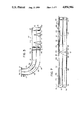
- FIG. 1 schematically illustrates a furnace formed according to the principles of the present invention
- FIG. 2 is a plan view from above of a detail of the furnace of FIG. 1;
- FIGS. 3, 4, 5, 6 and 7 are sections taken respectively, on the lines III--III, IV--IV, V--V, VI--VI, and VII--VII of FIG. 2.
- a furnace for firing the insulating plastics resin cladding of electrically conductive copper wires is generally indicated with the reference numeral 1, which furnace comprises, in a known way, a vertical principal chamber 2 provided with a lower inlet opening 3 and an upper outlet opening 4, through which chamber the wire 5 advances longitudinally in a continuous manner.
- This chamber 2 has an elongate form and comprises a first portion 6 of pyramid section increasing towards the inlet opening 3 and a second portion 7 of substantially constant rectangular section.
- heating elements 9 conveniently constituted by electrical resistors.
- Two thermocouples 10 housed in said first portion 6 and a thermocouple 11 housed in the second portion 7 close to the outlet opening 4 detect the temperatures in these portions and constitute the sensors of a temperature regulation system as described hereinbelow.
- the furnace 1 further includes an auxiliary unit 14 disposed alongside the principal chamber 2; this auxiliary unit 14 comprises a fan 15 facing an aspiration opening 16 communicating with the principal chamber 2 close to the junction between the two portions 6, 7 of the chamber 2 itself and operable to draw in a first stream 17 of a mixture of air and solvent vapours produced in the first portion 6, and a heating assembly 18.
- This heating assembly 18 is constituted by a heat exchanger 19, an electrical resistance heater 20, and a catalytic plate combustion chamber 21.
- a primary circuit 19a of the heat exchanger 19, the heater 20 and the combustion chamber 21 are disposed in series downstream of the fan 15.
- a duct 23 carries a second stream 24 exiting from the combustion chamber 21 to a secondary circuit 19b of the heat exchanger 19 in counter current with respect to the primary circuit 19a in such a way as to pre-heat the first stream 17 entering the heater 20.
- a fan 34 draws a first volume of air 35 from the exterior and delivers it into a duct 36 which, together with the first portion 28 of the second stream 24 flowing in the duct 26 flows into the recirculation duct 29 which opens into the second portion 7 of the principal chamber 2 through an aperture 37 which can be closed by a gate valve 41; the arrangement of the recirculation duct 29 is such as to introduce a third stream 38 resulting from the mixture of the first portion 28 of the second stream 24 with said first volume 35 of air in a direction substantially opposite the direction of advancement of the wire 5.
- the furnace 1 further includes a second heat exchanger 39 a primary circuit 39a of which is disposed in series with said duct 27 and a secondary circuit 39b of which, connected to counter current with respect to the first, is disposed in series with a duct 40 which conveys a second volume of air 43 from a fan 44, which draws it from the external environment, to a duct 45 for introduction into the first portion 6 of the principal chamber 2.
- thermocouples 46, 47 are disposed respectively in the heater 20 and at the outlet of the combustion chamber 21.
- the inlet opening 3 and the introduction duct 45 into the first portion 6 are integrated a single diffuser element 50 illustrated in detail in Figures from 2 to 7.
- This diffuser element 50 is conveniently made in sheet metal by conventional metal fabrication operations. The welds have not been represented for simplicity and clarity.
- the diffuser element 50 comprises a central body 51 of substantially rectangular form composed of a pair of tubular elements 52, 53 of rectangular section superimposed over one another and defining respective closed ducts 54, 55 of elongate rectangular form.
- a frame 57 of sheet metal of greater thickness is welded on an upper face 56 of the upper tubular element 52 into which, in use, is screwed a plurality of screws not illustrated for connecting the element 50 to a peripheral flange 58 (FIG. 1) of the first portion 6 of the principal chamber 2.
- a sheet metal plate 60 On a lower face 59 of the lower tubular element 53 is welded a sheet metal plate 60 provided with a longitudinal aperture 63 which extends over the whole length of the diffuser element 50 substantially along a major median of the diffuser element 50 itself, and has upwardly curved edges 64; at the ends of these edges 64 are welded two respective plates 65 inclined downwardly and towards the center of the diffuser element 50 and together defining the said inlet opening 3.
- the plate 60 is provided with a plurality of peripheral connecting holes 66 and has a dimension in plan greater than the tubular element 53; in particular it is arranged in such a way that the edges of two of its adjacent sides 67, 68 coincide with the edges of two corresponding sides 69, 70 of the tubular element 53, whilst the remaining two sides project with respect to this latter.
- connection of the plate 60 to a supporting structure of the furnace 1, not illustrated, is achieved by means of a plurality of bolts 71 which engage the said holes 66; in particular the bolts 71 disposed on the sides 67, 68 are housed in the through holes 72 of the tubular element 53, which are coaxial with and superimposed over the holes 66, and their heads are welded to the element 53 itself.
- the tubular elements 52 and 53 have internal dividing walls which separate the respective ducts 54, 55 into a plurality of chambers.
- a wall 74 is disposed vertically and transversely on half of the side 70 of the ducts 54, 55; two walls 75, 76 are disposed on the same side, on opposite sides with respect to the wall 74, and define with it, respectively, two chambers 77, 78 in the duct 54 and two chambers 79, 80 in the duct 55 in superimposed pairs.
- the chambers 79 and 80 are further divided in a longitudinal sense by a vertical wall 84 in the outer chambers 79a, 80a and the inner chambers 79b, 80b (FIG. 5).
- Two further vertical walls 85 which project obliquely towards the outside from an inner terminal corner of the tubular elements 52, 53 define, with the walls 75, 76 respectively, two further chambers 86, 87 in the duct 54 flanked by opposite sides of the chambers 77, 78, and two further chambers 88, 89 in the duct 55 facing opposite sides of the chambers 79, 80.
- the walls 75 and 76 do not intercept the entire section of the ducts 54, 55 but are open along the chambers 79a and 80a which therefore communicate respectively with the chambers 88 and 89.
- the chambers 88, 79b, 80b and 89 communicate with the interior of the central element 51 by means of respective lower longitudinal apertures 93, 94, 95, 96.
- the chambers 77 and 78 communicate with the chambers 79b and 80b by means of respective apertures 97 in the tubular elements 52 and 53.
- the tubular elements 52 and 53 comprise further internal dividing walls along one side 98 opposite the side 70, and in particular a central wall 100 opposite the wall 74 and a pair of side walls 101, 102 opposite the walls 75 and 76.
- the wall 100 intersects the lower duct 55 and upper duct 54 and divides this latter into two sections 103, 104 lying between the wall 100 and the walls 85; the walls 101, 102 on the other hand only intersect the lower duct 55 and define with the central wall 100 two chambers 105, 106, and with the walls 85 two sections 107, 108.
- the sections 103, 104 communicate respectively with the chambers 105, 106 through longitudinal apertures 109, 110 of the tubular elements 52, 53; the section 107, the chambers 105, 106 and the section 108 communicate with the interior of the central element 51 through respective lower longitudinal apertures 113, 114, 115, 116 counterposed respectively to said apertures 93, 94, 95, 96.
- the inlet duct 45 has an increasing section from an inlet portion 120 of rectangular section and vertical axis, provided with the flange 121 for attachment to the duct 40, and an exit portion 122 peripherally welded to the central element 51 and in particular to the tubular elements 52, 53 along their sides 70.
- the duct 45 has three respective internal bulkheads 123 of a form such as to divide each section of the duct 45 transversely into four substantially equal parts, which terminate, in the outlet portion 122 at the inner walls 74, 75 and 76 of the tubular elements 52, 53; the duct 45 further includes a fourth internal bulkhead 124 substantially normal, section by section, to the preceding ones and disposed along a median curved surface of the duct 45 which terminates in the outlet portion 122 substantially at the plane of contact between the tubular elements 52 and 53.
- the duct 45 is therefore subdivided into eight longitudinal chambers 45a, 45b, 45c, 45d, 45e, 45f, 45g, 45h as illustrated in FIG. 2.
- the tubular element 52 has on its side 70 a pair of terminal apertures 125, 126 which put the chambers 45a and 45d respectively into communication with the sections 103 and 104, and a pair of central apertures 127, 128 which put the chambers 45b and 45c respectively into communication with the chambers 77 and 78 of the duct 54; in an entirely similar way the tubular element 53 has on its side 70 a pair of terminal apertures 129, 130 which put the chambers 45h and 45e respectively into communication with the sections 107 and 108, and a pair of central apertures 131, 132 which put the chambers 45g and 45f respectively into communication with the chambers 79a and 80a of the duct 55.
- FIGS. 2, 3 and 4 it is finally seen that on the duct 45 are welded two hollow threaded sleeves 133 in correspondence with respective holes 134 of the duct 45 itself and having the purpose of permitting the connection of fluidodynamic parameter sensing instruments (for example manometers) of the conventional type and therefore not illustrated.
- the operation of the furnace 1 is as follows.
- the wire 5 enters into the peripheral chamber 2 through the inlet opening 3 and passes through the first portion 6 in which evaporation of solvents from the resins which constitute the cladding take place; it then passes into the second portion 7, maintained at a higher temperature than that of the portion 6, in which polymerization and cross linking of the resins take place.
- the first stream 17 drawn by the fan 15 and sent to the heating unit 18 is substantially constituted by a mixture of air and solvent vapours. This mixture is first preheated by the heat exchanger 19 and then carried by the heater 20 to a temperature sufficient to trigger combustion of the vapours.
- the catalytic plate combustion chamber 21 facilitates complete oxidation of these vapours into harmless combustion products (carbon dioxide and steam) which constitute, together with possible excess air, the second stream 24 which yields part of its thermal energy to the first stream 17 in the heat exchanger 19.
- This second stream 24 is then divided.
- the first portion 28, mixed with the air 35 introduced by the fan 34, is introduced in counter current into the second chamber 7 for the dual purpose of controlling its temperature in dependence on values detected by the thermocouple 11 and preventing a heavy flow of hot fluid through the outlet opening 4 by the chimney effect.
- These effects are controlled both by suitably throttling the aperture 37 by means of the valve 41 and by varying the speed of the fan 34 and therefore the rate of flow of cold air 35.
- the second portion 30 of the second stream 24 yields the greatest possible part of its thermal energy to the air 43 and is then sent to the chimney at a relatively low temperature.
- the air 43 reaches the duct 45 of the diffuser element 50 and is then introduced into the first portion 6 of the principal chamber 2 as described in detail.
- the air stream 43 is divided by the bulkheads 123, 124 of the duct 45 into eight streams 43a, 43b, 43c, 43d, 43e, 43f, 43g, 43h which feed the chambers of the duct 45 indicated with the same reference letters.
- the description of the path followed by said streams is effected with reference only to one half (the left half in FIG. 2) of the diffuser 50 and can be easily extended to the other half with evident considerations of symmetry with respect to a median vertical plane of the diffuser 50 itself.
- the stream 43a passes from the chamber 45a through the aperture 125 into the section 103 of the duct 54 and flows through it until it encounters the aperture 109 (FIG. 5); it then passes into the underlying chamber 105 and from this, through the aperture 114, to the interior of the central element 51.
- the stream 43b passes from the chamber 45b through the aperture 127 into the chamber 77 and from this into the chamber 79b through the aperture 97; finally, via the aperture 94 it flows into the interior of the central element 51.
- the stream 43g enters from the chamber 45g into the chamber 79a and then into the chamber 88 (FIG. 6) communicating with it, from which it flows out through the aperture 93.
- the stream 43h passes from the chamber 45h in the section 107 of the duct 55 through the aperture 129 and from this it flows to the interior of the central element 51 through the aperture 113.
- All the streams are then deflected upwardly by the edges 64 of the aperture 63 of the plate 60 in such a way as to pass into a lateral zone of the first portion 6 of the principal chamber 2; the introduction of the streams into the first portion 6 of the principal chamber 2 takes place with a velocity conveniently less than 1 m/s and preferably about 0.3-0.4 m/s.
- the introduction of the stream 43 into the principal chamber 2 achieves the dual purpose of re-using the thermal energy of the second portion 30 of the stream 24 which would otherwise be lost, and of reducing the intake of cold air by the chimney effect from the inlet opening 3.
- thermocouples 10 are controlled, in dependence on the signals from the thermocouples 10, by varying the speed of the fans 44 and 33, that is to say by varying the rate of flow of the second portion 30 of the second stream 24 and cold air 43.
- the rate at which heat is provided by the heating elements 9 and by the heating unit 18, as well as the rate of flow of the first stream 17 are varied.
- the particular geometry of the diffuser at the inlet of the first portion 6 of the principal chamber 2 causes a regular introduction of air 43 distributed around the side walls 8 of the portion 6 itself, that is to say avoiding a violent interaction of the air 43 with the cladding of the wire 5.
- the speed at which the air 43 is introduced is moreover particularly modest thanks to the expansion of the portion 6 towards the diffuser.
- the configuration of the furnace installation can be changed; for example, two or more principal chambers can be present, operating at different temperatures; rather than introducing into the first portion 6 of the principal chamber 1 external air 43 heated by means of the heat exchanger 39, all or part of the second stream 24 can be reintroduced, possibly mixed with external air.
- the points of withdrawal of the first stream 17, the points of introduction of the third stream 38, as well as the elements constituting the heater unit 18 can be changed: the heat exchanger 19 can be omitted, the heater 20 can be a gas heater, the heating elements 9 of the first portion 6 of the principal chamber 2 can be omitted.
- the number and forms of the ducts constituting the diffuser element 50 can be changed.
Landscapes
- Engineering & Computer Science (AREA)
- Mechanical Engineering (AREA)
- General Engineering & Computer Science (AREA)
- Chemical & Material Sciences (AREA)
- Textile Engineering (AREA)
- Chemical Kinetics & Catalysis (AREA)
- Environmental & Geological Engineering (AREA)
- Combustion & Propulsion (AREA)
- Life Sciences & Earth Sciences (AREA)
- Sustainable Development (AREA)
- Incineration Of Waste (AREA)
- Heating, Cooling, Or Curing Plastics Or The Like In General (AREA)
- Furnace Details (AREA)
Abstract
Description
Claims (15)
Applications Claiming Priority (2)
| Application Number | Priority Date | Filing Date | Title |
|---|---|---|---|
| IT8752927U IT210435Z2 (en) | 1987-01-30 | 1987-01-30 | VERTICAL OVEN FOR THE COOKING OF FILIFFORM Artifacts |
| IT52927/87[U] | 1987-01-30 |
Publications (1)
| Publication Number | Publication Date |
|---|---|
| US4856986A true US4856986A (en) | 1989-08-15 |
Family
ID=11278586
Family Applications (1)
| Application Number | Title | Priority Date | Filing Date |
|---|---|---|---|
| US07/150,031 Expired - Fee Related US4856986A (en) | 1987-01-30 | 1988-01-29 | Vertical furnace for firing wire-like products |
Country Status (4)
| Country | Link |
|---|---|
| US (1) | US4856986A (en) |
| DE (1) | DE3802475A1 (en) |
| IT (1) | IT210435Z2 (en) |
| RU (1) | RU2021570C1 (en) |
Cited By (8)
| Publication number | Priority date | Publication date | Assignee | Title |
|---|---|---|---|---|
| US4938689A (en) * | 1987-01-30 | 1990-07-03 | Societa' Industriale Costruzioni Microelettriche S.I.C.M.E. S.P.A. | Furnace for firing wire-like products |
| US4999166A (en) * | 1987-03-02 | 1991-03-12 | Societa' Industriale Costruzioni Microelettriche | Furnace for firing wire-like products |
| US5018966A (en) * | 1989-03-20 | 1991-05-28 | Hunter Engineering Company, Inc. | Strip drying or curing oven |
| US5291670A (en) * | 1988-12-23 | 1994-03-08 | S.I.C.M.E. S.P.A. Societa Industriale Costruzioni Microelettriche | Process for baking wire-like products clad in insulating plastics resin, and an oven for performing the said method |
| USD521493S1 (en) * | 2005-01-21 | 2006-05-23 | Koninklikjke Philips Electronics, N.V. | Gaming headphone |
| US7133726B1 (en) * | 1997-03-28 | 2006-11-07 | Applera Corporation | Thermal cycler for PCR |
| EP1790928A1 (en) * | 2005-11-25 | 2007-05-30 | Advanced Photonics Technologies AG | Coil coating process and apparatus |
| US20160284445A1 (en) * | 2015-03-28 | 2016-09-29 | Y Generation Technologies Company Limited | Energy efficient copper wire production system |
Families Citing this family (1)
| Publication number | Priority date | Publication date | Assignee | Title |
|---|---|---|---|---|
| DE59007706D1 (en) * | 1990-12-13 | 1994-12-15 | Boockmann Gmbh | Method and device for impregnating and / or coating objects. |
Citations (2)
| Publication number | Priority date | Publication date | Assignee | Title |
|---|---|---|---|---|
| US4303387A (en) * | 1980-12-09 | 1981-12-01 | Hudson Wire Company | Enameled wire oven |
| US4448578A (en) * | 1982-04-30 | 1984-05-15 | Acrometal Products, Inc. | Curing oven for enameled wire and control system therefor |
-
1987
- 1987-01-30 IT IT8752927U patent/IT210435Z2/en active
-
1988
- 1988-01-28 DE DE3802475A patent/DE3802475A1/en not_active Withdrawn
- 1988-01-29 RU SU884355139A patent/RU2021570C1/en active
- 1988-01-29 US US07/150,031 patent/US4856986A/en not_active Expired - Fee Related
Patent Citations (2)
| Publication number | Priority date | Publication date | Assignee | Title |
|---|---|---|---|---|
| US4303387A (en) * | 1980-12-09 | 1981-12-01 | Hudson Wire Company | Enameled wire oven |
| US4448578A (en) * | 1982-04-30 | 1984-05-15 | Acrometal Products, Inc. | Curing oven for enameled wire and control system therefor |
Cited By (16)
| Publication number | Priority date | Publication date | Assignee | Title |
|---|---|---|---|---|
| US4938689A (en) * | 1987-01-30 | 1990-07-03 | Societa' Industriale Costruzioni Microelettriche S.I.C.M.E. S.P.A. | Furnace for firing wire-like products |
| US4999166A (en) * | 1987-03-02 | 1991-03-12 | Societa' Industriale Costruzioni Microelettriche | Furnace for firing wire-like products |
| US5291670A (en) * | 1988-12-23 | 1994-03-08 | S.I.C.M.E. S.P.A. Societa Industriale Costruzioni Microelettriche | Process for baking wire-like products clad in insulating plastics resin, and an oven for performing the said method |
| US5018966A (en) * | 1989-03-20 | 1991-05-28 | Hunter Engineering Company, Inc. | Strip drying or curing oven |
| US20100173400A1 (en) * | 1997-03-28 | 2010-07-08 | Life Technologies Corporation | Thermal Cycler for PCR |
| US7133726B1 (en) * | 1997-03-28 | 2006-11-07 | Applera Corporation | Thermal cycler for PCR |
| US20070113880A1 (en) * | 1997-03-28 | 2007-05-24 | Applera Corporation | Thermal cycler for PCR |
| US9776187B2 (en) | 1997-03-28 | 2017-10-03 | Applied Biosystems, Llc | Thermal cycler for PCR |
| US9044753B2 (en) | 1997-03-28 | 2015-06-02 | Applied Biosystems, Llc | Thermal cycler for PCR |
| US20080314431A1 (en) * | 1997-03-28 | 2008-12-25 | Applied Biosystems, Inc. | Thermal cycler for PCR |
| US8246243B2 (en) | 1997-03-28 | 2012-08-21 | Applied Biosystems, Llc | Thermal cycler for PCR |
| USD521493S1 (en) * | 2005-01-21 | 2006-05-23 | Koninklikjke Philips Electronics, N.V. | Gaming headphone |
| US20090029062A1 (en) * | 2005-11-25 | 2009-01-29 | Advanced Photonics Technologies Ag | Coil coating process and apparatus |
| WO2007060009A1 (en) * | 2005-11-25 | 2007-05-31 | Advanced Photonics Technologies Ag | Coil coating process and apparatus |
| EP1790928A1 (en) * | 2005-11-25 | 2007-05-30 | Advanced Photonics Technologies AG | Coil coating process and apparatus |
| US20160284445A1 (en) * | 2015-03-28 | 2016-09-29 | Y Generation Technologies Company Limited | Energy efficient copper wire production system |
Also Published As
| Publication number | Publication date |
|---|---|
| RU2021570C1 (en) | 1994-10-15 |
| IT210435Z2 (en) | 1988-12-30 |
| IT8752927V0 (en) | 1987-01-30 |
| DE3802475A1 (en) | 1988-08-11 |
Similar Documents
| Publication | Publication Date | Title |
|---|---|---|
| US4856986A (en) | Vertical furnace for firing wire-like products | |
| JP3124927B2 (en) | Direct cooling, pre-ignition furnace | |
| US4312480A (en) | Radiation shielding and gas diffusion apparatus | |
| US4876851A (en) | Infrared radiation screening device | |
| US3626922A (en) | Forced convection oven | |
| US4589844A (en) | Heat exchange apparatus for industrial furnaces | |
| GB1011742A (en) | Improvements in or relating to an induction type room air conditioning unit | |
| IT9009370A1 (en) | PERFECTED BURNER FOR OIL AND COMBUSTIBLE GASES WITH LOW NITROGEN OXIDE PRODUCTION. | |
| GB1188699A (en) | Improvements in or relating to Cooling Apparatus | |
| EP0328418B1 (en) | Radiant tube furnace and method of burning a fuel | |
| US4286548A (en) | Gas recirculation apparatus with integral ash hoppers | |
| US1991449A (en) | Furnace | |
| US4309978A (en) | Forced air heater | |
| US4938689A (en) | Furnace for firing wire-like products | |
| GB2024403A (en) | Flame-holder | |
| US4573909A (en) | Billet heating furnace with adjustable pressurized entrance seal | |
| US2417606A (en) | Furnace for the production of carbon black | |
| US3001779A (en) | Air heater | |
| US3437322A (en) | Air-heating gas burner | |
| US3174464A (en) | Vapor generating apparatus | |
| IE913468A1 (en) | Compact gas-fired air heater | |
| US4999166A (en) | Furnace for firing wire-like products | |
| US2479940A (en) | Multiple tube air heating furnace | |
| US6984124B2 (en) | High temperature rise makeup air unit | |
| US1361351A (en) | Air-heater |
Legal Events
| Date | Code | Title | Description |
|---|---|---|---|
| AS | Assignment |
Owner name: SOCIETA ' INDUSTRIALE COSTRUZIONI MICROELETTRICHE, Free format text: ASSIGNMENT OF ASSIGNORS INTEREST.;ASSIGNORS:MACOCCO, DINO;RICCO, MICHELE;REEL/FRAME:004839/0654 Effective date: 19880107 Owner name: SOCIETA ' INDUSTRIALE COSTRUZIONI MICROELETTRICHE, Free format text: ASSIGNMENT OF ASSIGNORS INTEREST;ASSIGNORS:MACOCCO, DINO;RICCO, MICHELE;REEL/FRAME:004839/0654 Effective date: 19880107 |
|
| FEPP | Fee payment procedure |
Free format text: PAYOR NUMBER ASSIGNED (ORIGINAL EVENT CODE: ASPN); ENTITY STATUS OF PATENT OWNER: SMALL ENTITY |
|
| FPAY | Fee payment |
Year of fee payment: 4 |
|
| FEPP | Fee payment procedure |
Free format text: PAYER NUMBER DE-ASSIGNED (ORIGINAL EVENT CODE: RMPN); ENTITY STATUS OF PATENT OWNER: SMALL ENTITY Free format text: PAYOR NUMBER ASSIGNED (ORIGINAL EVENT CODE: ASPN); ENTITY STATUS OF PATENT OWNER: SMALL ENTITY |
|
| FEPP | Fee payment procedure |
Free format text: PAYER NUMBER DE-ASSIGNED (ORIGINAL EVENT CODE: RMPN); ENTITY STATUS OF PATENT OWNER: SMALL ENTITY Free format text: PAYOR NUMBER ASSIGNED (ORIGINAL EVENT CODE: ASPN); ENTITY STATUS OF PATENT OWNER: SMALL ENTITY |
|
| REMI | Maintenance fee reminder mailed | ||
| LAPS | Lapse for failure to pay maintenance fees | ||
| FP | Lapsed due to failure to pay maintenance fee |
Effective date: 19970820 |
|
| STCH | Information on status: patent discontinuation |
Free format text: PATENT EXPIRED DUE TO NONPAYMENT OF MAINTENANCE FEES UNDER 37 CFR 1.362 |