US4847478A - Optical pick-up device - Google Patents
Optical pick-up device Download PDFInfo
- Publication number
- US4847478A US4847478A US07/195,972 US19597288A US4847478A US 4847478 A US4847478 A US 4847478A US 19597288 A US19597288 A US 19597288A US 4847478 A US4847478 A US 4847478A
- Authority
- US
- United States
- Prior art keywords
- light
- regions
- recording medium
- optical member
- lines
- Prior art date
- Legal status (The legal status is an assumption and is not a legal conclusion. Google has not performed a legal analysis and makes no representation as to the accuracy of the status listed.)
- Expired - Lifetime
Links
- 230000003287 optical effect Effects 0.000 title claims abstract description 45
- 230000004075 alteration Effects 0.000 claims abstract description 15
- 230000001678 irradiating effect Effects 0.000 claims abstract 5
- 238000009826 distribution Methods 0.000 description 8
- 201000009310 astigmatism Diseases 0.000 description 6
- 238000000034 method Methods 0.000 description 6
- 206010010071 Coma Diseases 0.000 description 4
- 238000010586 diagram Methods 0.000 description 3
- 230000007423 decrease Effects 0.000 description 2
- 230000001419 dependent effect Effects 0.000 description 1
- 230000000694 effects Effects 0.000 description 1
- 239000011521 glass Substances 0.000 description 1
- 230000004048 modification Effects 0.000 description 1
- 238000012986 modification Methods 0.000 description 1
- 239000004065 semiconductor Substances 0.000 description 1
Images


Classifications
-
- G—PHYSICS
- G11—INFORMATION STORAGE
- G11B—INFORMATION STORAGE BASED ON RELATIVE MOVEMENT BETWEEN RECORD CARRIER AND TRANSDUCER
- G11B7/00—Recording or reproducing by optical means, e.g. recording using a thermal beam of optical radiation by modifying optical properties or the physical structure, reproducing using an optical beam at lower power by sensing optical properties; Record carriers therefor
- G11B7/12—Heads, e.g. forming of the optical beam spot or modulation of the optical beam
- G11B7/135—Means for guiding the beam from the source to the record carrier or from the record carrier to the detector
- G11B7/1365—Separate or integrated refractive elements, e.g. wave plates
-
- G—PHYSICS
- G11—INFORMATION STORAGE
- G11B—INFORMATION STORAGE BASED ON RELATIVE MOVEMENT BETWEEN RECORD CARRIER AND TRANSDUCER
- G11B7/00—Recording or reproducing by optical means, e.g. recording using a thermal beam of optical radiation by modifying optical properties or the physical structure, reproducing using an optical beam at lower power by sensing optical properties; Record carriers therefor
- G11B7/08—Disposition or mounting of heads or light sources relatively to record carriers
- G11B7/09—Disposition or mounting of heads or light sources relatively to record carriers with provision for moving the light beam or focus plane for the purpose of maintaining alignment of the light beam relative to the record carrier during transducing operation, e.g. to compensate for surface irregularities of the latter or for track following
- G11B7/0908—Disposition or mounting of heads or light sources relatively to record carriers with provision for moving the light beam or focus plane for the purpose of maintaining alignment of the light beam relative to the record carrier during transducing operation, e.g. to compensate for surface irregularities of the latter or for track following for focusing only
- G11B7/0909—Disposition or mounting of heads or light sources relatively to record carriers with provision for moving the light beam or focus plane for the purpose of maintaining alignment of the light beam relative to the record carrier during transducing operation, e.g. to compensate for surface irregularities of the latter or for track following for focusing only by astigmatic methods
-
- G—PHYSICS
- G11—INFORMATION STORAGE
- G11B—INFORMATION STORAGE BASED ON RELATIVE MOVEMENT BETWEEN RECORD CARRIER AND TRANSDUCER
- G11B7/00—Recording or reproducing by optical means, e.g. recording using a thermal beam of optical radiation by modifying optical properties or the physical structure, reproducing using an optical beam at lower power by sensing optical properties; Record carriers therefor
- G11B7/08—Disposition or mounting of heads or light sources relatively to record carriers
- G11B7/09—Disposition or mounting of heads or light sources relatively to record carriers with provision for moving the light beam or focus plane for the purpose of maintaining alignment of the light beam relative to the record carrier during transducing operation, e.g. to compensate for surface irregularities of the latter or for track following
- G11B7/094—Methods and circuits for servo offset compensation
-
- G—PHYSICS
- G11—INFORMATION STORAGE
- G11B—INFORMATION STORAGE BASED ON RELATIVE MOVEMENT BETWEEN RECORD CARRIER AND TRANSDUCER
- G11B7/00—Recording or reproducing by optical means, e.g. recording using a thermal beam of optical radiation by modifying optical properties or the physical structure, reproducing using an optical beam at lower power by sensing optical properties; Record carriers therefor
- G11B7/12—Heads, e.g. forming of the optical beam spot or modulation of the optical beam
- G11B7/13—Optical detectors therefor
- G11B7/133—Shape of individual detector elements
-
- G—PHYSICS
- G11—INFORMATION STORAGE
- G11B—INFORMATION STORAGE BASED ON RELATIVE MOVEMENT BETWEEN RECORD CARRIER AND TRANSDUCER
- G11B7/00—Recording or reproducing by optical means, e.g. recording using a thermal beam of optical radiation by modifying optical properties or the physical structure, reproducing using an optical beam at lower power by sensing optical properties; Record carriers therefor
- G11B7/12—Heads, e.g. forming of the optical beam spot or modulation of the optical beam
- G11B7/135—Means for guiding the beam from the source to the record carrier or from the record carrier to the detector
- G11B7/1353—Diffractive elements, e.g. holograms or gratings
Definitions
- the present invention relates to an optical pick-up device suitable for use with an apparatus such as an optical disc player, a compact disc player or an optical video disc player.
- FIG. 1 shows a block diagram of a conventional optical pick-up device used in an optical disc system.
- Rays of divergent light, i.e., laser beams, emerging from a light source 1 such as a semiconductor laser or the like are reflected by a surface of a parallel plane plate 2 and thereafter strike on objective lens 3.
- the objective lens converges the light incident thereto and irradiates a disc 4 (recording medium) with the converged light.
- the rays of divergent light reflected from the disc 4 are condensed by the objective lens 3.
- the rays then pass through the plane 2 and are converged on a photo detector 5.
- the plate e.g., an optical member formed with a glass plate, is disposed in the middle of a light path leading to the photo detector 5, and hence astigmatism is created in the light incident upon the photo detector.
- the photo detector 5 is, as depicted in FIGS. 2(aa)-2(d) divided into four regions D 1 to D 4 by first and second rectilinear lines 51 and 52, respectively.
- the line 51 is drawn parallel to a track on the disc 4 and the line 52 is perpendicular to the line 51.
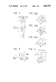
- the spot light incident on the photo detector 5 assumes a substantially circular configuration, as illustrated in FIG. 2(b).
- the spot light assumes a substantially vertically or laterally elongated elliptical shape as shown in FIGS. 2(a) and 2(c), respectively.
- This phenomenon enables focussing and tracking errors to be corrected using a so-called astigmatism method and a so-called push-pull method.
- a focus error signal is generated based on a difference between a first sum of outputs of the regions D 1 and D 3 and a second sum of outputs of the regions D 2 and D 4 .
- a tracking error signal can also be produced based on a difference between a third sum of outputs of the regions D 1 and D 2 and a fourth sum of outputs of the regions D 3 and D 4 .
- FIG. 4 illustrates a situation where the light from the spot light which is incident on the disc 4 (at "an information detecting point") is projected (light beam tracking) on the photo detector 5 through the objective lens 3 and the plate 2 which cause a coma aberration and an astigmatism.
- the light with which the disc 4 is irradiated is, as illustrated in FIG. 3, diffracted by a track (e.g. a pit thereof) on the disk, while the objective lens 3 serves to condense the Oth-dimensional diffraction light and positive/negative ( ⁇ ) dimensional diffraction light (created by the plate 2) in FIG. 4.
- FIG. 5(a) An exemplary distribution of light on the photo detector 5 in the case of densely arranged tracks (narrow track pitch) is depicted in FIG. 5(a).
- exemplary distributions are shown in FIGS. 5(b)-5(d), in order of increasing track pitch.
- the first curved line 61 has (-) primary diffraction light and Oth-dimensional light to its left, where the line 61 is concave.
- the second curved line 62 has (+) primary diffraction light and Oth-dimensional light to its right, where the line 62 is concave. In the area of FIG. 4 between the convex portions of the curved lines 61 and 62, there is Oth-dimensional light.
- FIGS. 6(a)-6(d) respectively show the distribution curve and the dividing lines 51, 52 on the photo detector 5 in FIGS. 5(a)-5(d) projected from the photo detector onto the objective lens 3 through the plate 2.
- a quantity (D 1 +D 2 ) of the (-) primary diffraction light in the regions D 1 and D 2 is equal to a quantity (D 3 l +D 4 ) of the (+) primary diffraction light in the regions D 3 and D 4 .
- the quantity of Oth-dimensional diffraction light in the regions D 1 and D 2 (D 1 +D 2 ) is greater than that in the regions D 3 and D 4 (D 3 +D 4 ).
- the Oth-dimensional diffraction light and the ( ⁇ ) primary diffraction light are synthesized, whereby the generated tracking error signal does not become zero (i.e. (D 1 +D 2 )-(D 3 +D 4 ) ⁇ 0). Therefore, if the objective lens 3 is tracking-controlled using the tracking error signal, the spot light (information detecting point) will respond to the tracking error signal by moving farther away from the track on which it is intended to be directed.
- the spot light (the information detecting point) traverses the track.
- an imbalance takes place in the ( ⁇ ) primary diffraction light: one (e.g. (+)) is bright, whereas the other (e.g. (-)) is dark.
- the distribution of (-) primary diffraction light in the region D 1 is wider than in the region D 2 .
- the distribution of (+) primary diffraction light in the region D 4 is wider than in the region D 3 . Consequently, the (-) primary diffraction light becomes dark, whereas the (+) primary diffraction light becomes bright.
- the sum of outputs of the regions D 1 and D 3 decreases, while the sum of outputs of the regions D 2 and D 4 increases. Therefore, the information detecting point traverses the track. It follows that an offset component is produced in the focus error signal.
- the conventional device is arranged such that another parallel plane plate 6 (or a cylindrical lens) is disposed facing in an opposite direction to the plate 2 to correct the comatic aberration thereof.
- This arrangement requires increasing the number of parts, consequently increasing the cost, complexity and size of the device.
- An optical pick-up device includes a light source for emitting light with which a recording medium is irradiated for the purpose of recording and/or reproducing information and an objective lens for condensing beams of light reflected by the recording medium.
- the device also includes a photo detector for detecting the beams of light passing through the objective lens, and an optical member (such as a parallel plane plate), disposed in the middle of a light path from the lens to the photo detector.
- the photo detector is divided into a plurality of region in accordance with curved lines, which are the projections onto the photo detector, through the objective lens and the optical member, of first and second rectilinear lines which are parallel and perpendicular to a track on the recording medium respectively.
- the recording medium of the disk is irradiated with the light emitted from the light source.
- the objective lens serves to condense rays of light which are being transmitted to the recording medium or have been reflected by this medium.
- the thus condensed light is detected by the photo detector through the optical member.
- the photo detector is divided by the first and second curved lines as defined above. Consequently, the same function as that in an ideal case where there is no coma aberration is provided even when there is a comatic aberration (in the light incident on the photo detector) caused by the optical member in the inventive device.
- FIG. 1 is a block diagram of a conventional optical pick-up device
- FIGS. 2(a)-2(d) are plan views of the photo detector in the device of FIG. 1;
- FIG. 3 is a side view illustrating diffraction from a track of a recording medium
- FIGS. 4 and 5(a)-5(d) are plan views each illustrating the photo detector of FIG. 1;
- FIGS. 6(a)-6(d) are explanatory views showing a case where the photo detector is projected on an objective lens of the device;
- FIG. 7 is a block diagram illustrating a modification to the device of FIG. 1;
- FIGS. 8 and 9(a)-9(d) are plan views each illustrating a photo detector of an optical pick-up device according to the present invention.
- FIGS. 10(a)-10(d) are explanatory views showing a case where the photo detector according to the invention is projected on an objective lens.
- An optical pick-up device can be constructed the same as the conventional device shown in FIG. 1; however, the way in which the light-receiving surface of the photo detector is divided is different.
- FIG. 8 shows a photo detector 50 according to the present invention (in lieu of the photo detector 5 of FIG. 1).
- the photo detector 50 is divided into four regions D 1 through D 4 by dividing lines 510 and 520.
- the dividing line 510 is defined as the curved line which is formed or projected (in light beam tracking) on the photo detector 50 from a rectilinear line parallel to a track on the disc 4 which first passes through the objective lens 3 and the parallel plane plate 2.
- the dividing line 520 is defined as the curved line formed or projected on the photo detector 50 from a rectilinear line perpendicular to the track on the disc 4. A line that is rectilinear on the disc 4 becomes curved after being projected on the photo detector because the plate 2 causes a coma aberration.
- the curved lines 510, 520 thus correspond to the rectilinear lines as they would appear on the photo detector due to the comatic aberration.
- FIGS. 9(a)-9(d) respectively show four variations in the distribution curve of ( ⁇ ) primary diffraction light which correspond to variations of the track pitch of the disc 4.
- FIG. 9(a) illustrates a case in which the track pitch is narrow
- FIGS. 9(b) and 9(d) each depict cases where the track pitch is wide.
- FIGS. 10(a)-10(d) each show a situation where the individual distribution depicted in FIGS. 9(a)-9(d) varies when projecting the curved lines on the objective lens 3 through the plate 2.
- the quantities of ( ⁇ ) primary diffraction light in each of the regions D 1 to D 4 equal.
- each of the quantities of rays of Oth-dimensional diffraction light are equal.
- the reflection rate of the disc 4 varies, its resultant influences are equally distributed in the respective regions D 1 to D 4 .
- no offset is produced in the tracking error signal.
- the output of the region D 1 is equal to that of the region D 2 , and similarly the outputs of the region D 3 and D 4 are equal. Consequently, there is no offset in the focus error signal.
- focus servo and tracking servo based on the astigmatism and push-pull methods can accurately be performed, without using an offset amount and in spite of a comatic aberration.
- the optical pick-up device includes: a light source for emitting light with which a recording medium is irradiated to record and reproduce information; an objective lens for condensing beams of light passing through the recording medium; an optical member for diffracting the condensed beams; and a photo detector for detecting the diffracted beams.
- the photo detector according to the present invention is divided into a plurality of regions in accordance with curved lines, projected on the photo detector through the objective lens and the optical member, into which respective rectilinear lines which are parallel and perpendicular to a track on the recording medium are changed due to comatic aberration of the optical member. With this arrangement, it is possible to completely or virtually completely correct the comatic aberration of the optical member without using any other optical parts and thereby decrease both the size and cost of the device.
Landscapes
- Physics & Mathematics (AREA)
- Optics & Photonics (AREA)
- Optical Recording Or Reproduction (AREA)
- Optical Head (AREA)
- Automatic Focus Adjustment (AREA)
Abstract
Description
Claims (9)
Applications Claiming Priority (2)
| Application Number | Priority Date | Filing Date | Title |
|---|---|---|---|
| JP62121623A JPS63285732A (en) | 1987-05-19 | 1987-05-19 | Optical pickup device |
| JP121623 | 1987-05-19 |
Publications (1)
| Publication Number | Publication Date |
|---|---|
| US4847478A true US4847478A (en) | 1989-07-11 |
Family
ID=14815842
Family Applications (1)
| Application Number | Title | Priority Date | Filing Date |
|---|---|---|---|
| US07/195,972 Expired - Lifetime US4847478A (en) | 1987-05-19 | 1988-05-19 | Optical pick-up device |
Country Status (4)
| Country | Link |
|---|---|
| US (1) | US4847478A (en) |
| EP (1) | EP0292289B1 (en) |
| JP (1) | JPS63285732A (en) |
| DE (1) | DE3877417T2 (en) |
Cited By (7)
| Publication number | Priority date | Publication date | Assignee | Title |
|---|---|---|---|---|
| US4970710A (en) * | 1987-07-29 | 1990-11-13 | Laser Magnetic Storage International Company | Method and apparatus for focus and tracking in an optical disk system |
| US5111449A (en) * | 1988-04-20 | 1992-05-05 | Sharp Kabushiki Kaisha | Optical pick-up device using diffraction grating element having two sub-regions |
| US5442615A (en) * | 1991-11-20 | 1995-08-15 | Sony Corporation | Optical plate for correcting comatic aberration |
| US5511050A (en) * | 1988-09-21 | 1996-04-23 | Hitachi, Ltd. | Focus error detecting method and optical head using the same |
| US5570338A (en) * | 1992-08-28 | 1996-10-29 | Toppan Printing Co., Ltd. | Optical information recording medium which uses diffraction grating |
| US20020048233A1 (en) * | 2000-09-07 | 2002-04-25 | Masakazu Ogasawara | Optical pickup device and focus error detecting method therefor |
| US6563101B1 (en) | 2000-01-19 | 2003-05-13 | Barclay J. Tullis | Non-rectilinear sensor arrays for tracking an image |
Families Citing this family (1)
| Publication number | Priority date | Publication date | Assignee | Title |
|---|---|---|---|---|
| JP2009110558A (en) * | 2007-10-26 | 2009-05-21 | Sanyo Electric Co Ltd | Optical pickup device |
Citations (2)
| Publication number | Priority date | Publication date | Assignee | Title |
|---|---|---|---|---|
| US4625303A (en) * | 1983-09-05 | 1986-11-25 | Mitsubishi Denki Kabushiki Kaisha | Automatic focusing device |
| US4742218A (en) * | 1985-03-11 | 1988-05-03 | Hitachi, Ltd. | Focus error detection apparatus utilizing focusing an front and rear sides of focal planes |
Family Cites Families (1)
| Publication number | Priority date | Publication date | Assignee | Title |
|---|---|---|---|---|
| JPS59125727U (en) * | 1983-02-15 | 1984-08-24 | パイオニア株式会社 | Optical information pickup device |
-
1987
- 1987-05-19 JP JP62121623A patent/JPS63285732A/en active Pending
-
1988
- 1988-05-19 EP EP88304549A patent/EP0292289B1/en not_active Expired - Lifetime
- 1988-05-19 DE DE8888304549T patent/DE3877417T2/en not_active Expired - Fee Related
- 1988-05-19 US US07/195,972 patent/US4847478A/en not_active Expired - Lifetime
Patent Citations (2)
| Publication number | Priority date | Publication date | Assignee | Title |
|---|---|---|---|---|
| US4625303A (en) * | 1983-09-05 | 1986-11-25 | Mitsubishi Denki Kabushiki Kaisha | Automatic focusing device |
| US4742218A (en) * | 1985-03-11 | 1988-05-03 | Hitachi, Ltd. | Focus error detection apparatus utilizing focusing an front and rear sides of focal planes |
Cited By (10)
| Publication number | Priority date | Publication date | Assignee | Title |
|---|---|---|---|---|
| US4970710A (en) * | 1987-07-29 | 1990-11-13 | Laser Magnetic Storage International Company | Method and apparatus for focus and tracking in an optical disk system |
| US5111449A (en) * | 1988-04-20 | 1992-05-05 | Sharp Kabushiki Kaisha | Optical pick-up device using diffraction grating element having two sub-regions |
| US5511050A (en) * | 1988-09-21 | 1996-04-23 | Hitachi, Ltd. | Focus error detecting method and optical head using the same |
| US5442615A (en) * | 1991-11-20 | 1995-08-15 | Sony Corporation | Optical plate for correcting comatic aberration |
| US5570338A (en) * | 1992-08-28 | 1996-10-29 | Toppan Printing Co., Ltd. | Optical information recording medium which uses diffraction grating |
| US5625619A (en) * | 1992-08-28 | 1997-04-29 | Toppan Printing Co., Ltd. | Optical recording medium having a plurality of different diffraction grating cells |
| US5644565A (en) * | 1992-08-28 | 1997-07-01 | Toppan Printing Co., Ltd. | Optical recording medium including a plurality of diffracted grating cells |
| US6563101B1 (en) | 2000-01-19 | 2003-05-13 | Barclay J. Tullis | Non-rectilinear sensor arrays for tracking an image |
| US20020048233A1 (en) * | 2000-09-07 | 2002-04-25 | Masakazu Ogasawara | Optical pickup device and focus error detecting method therefor |
| US6967908B2 (en) * | 2000-09-07 | 2005-11-22 | Pioneer Corporation | Optical pickup device with focus error detecting optical element and method for focus error detection |
Also Published As
| Publication number | Publication date |
|---|---|
| JPS63285732A (en) | 1988-11-22 |
| EP0292289B1 (en) | 1993-01-13 |
| DE3877417D1 (en) | 1993-02-25 |
| EP0292289A2 (en) | 1988-11-23 |
| DE3877417T2 (en) | 1993-05-13 |
| EP0292289A3 (en) | 1990-03-28 |
Similar Documents
| Publication | Publication Date | Title |
|---|---|---|
| US5065380A (en) | Diffraction grating for an optical pickup device | |
| US6353582B1 (en) | Pickup device | |
| US5638353A (en) | Optical head device | |
| US4771411A (en) | Device for scanning a radiation-reflecting information surface with optical radiation | |
| US5198916A (en) | Optical pickup | |
| US4847478A (en) | Optical pick-up device | |
| EP0612064B1 (en) | An optical pickup apparatus | |
| EP0475523B1 (en) | Device for optically scanning an information plane | |
| JP2002170256A (en) | Optical head device, recording and / or reproducing device, and recording and / or reproducing method | |
| EP0459764A2 (en) | Optical head device | |
| US5060214A (en) | Optical pickup device keeping coincident the optical axes of the objective lens and of the recording/reproducing beam | |
| US5202869A (en) | Optical head device including diffraction grating | |
| GB2137744A (en) | Optical information pickup apparatus | |
| JPH05325251A (en) | Optical head | |
| US6373797B1 (en) | Optical information recording/reproducing apparatus based on tracking control of irradiated light | |
| KR900008405B1 (en) | Optical head unit | |
| JP2858202B2 (en) | Optical pickup | |
| JP3514672B2 (en) | Method for manufacturing optical pickup device | |
| JPH0237533A (en) | Optical pickup device | |
| CA1046318A (en) | Opto-electronic system for determining a deviation between the actual and the desired position of a plane in an optical imaging system | |
| JPH02218022A (en) | Separate optical pickup device | |
| JP3222280B2 (en) | Optical pickup device | |
| KR0186153B1 (en) | Optical pickup device | |
| JP2614504B2 (en) | Tracking error detection method | |
| JPH0548534B2 (en) |
Legal Events
| Date | Code | Title | Description |
|---|---|---|---|
| AS | Assignment |
Owner name: PIONEER ELECTRONIC CORPORATION, NO. 4-1, MEGURO 1- Free format text: ASSIGNMENT OF ASSIGNORS INTEREST.;ASSIGNOR:SUGIURA, SATOSHI;REEL/FRAME:004908/0379 Effective date: 19880516 Owner name: PIONEER ELECTRONIC CORPORATION,JAPAN Free format text: ASSIGNMENT OF ASSIGNORS INTEREST;ASSIGNOR:SUGIURA, SATOSHI;REEL/FRAME:004908/0379 Effective date: 19880516 |
|
| STCF | Information on status: patent grant |
Free format text: PATENTED CASE |
|
| FEPP | Fee payment procedure |
Free format text: PAYOR NUMBER ASSIGNED (ORIGINAL EVENT CODE: ASPN); ENTITY STATUS OF PATENT OWNER: LARGE ENTITY |
|
| FPAY | Fee payment |
Year of fee payment: 4 |
|
| FEPP | Fee payment procedure |
Free format text: PAYER NUMBER DE-ASSIGNED (ORIGINAL EVENT CODE: RMPN); ENTITY STATUS OF PATENT OWNER: LARGE ENTITY Free format text: PAYOR NUMBER ASSIGNED (ORIGINAL EVENT CODE: ASPN); ENTITY STATUS OF PATENT OWNER: LARGE ENTITY |
|
| FPAY | Fee payment |
Year of fee payment: 8 |
|
| FPAY | Fee payment |
Year of fee payment: 12 |