US4846327A - Drive arrangement for compressor of a transport refrigeration unit - Google Patents
Drive arrangement for compressor of a transport refrigeration unit Download PDFInfo
- Publication number
- US4846327A US4846327A US06/741,089 US74108985A US4846327A US 4846327 A US4846327 A US 4846327A US 74108985 A US74108985 A US 74108985A US 4846327 A US4846327 A US 4846327A
- Authority
- US
- United States
- Prior art keywords
- clutch
- pulley
- compressor
- engine
- driven
- Prior art date
- Legal status (The legal status is an assumption and is not a legal conclusion. Google has not performed a legal analysis and makes no representation as to the accuracy of the status listed.)
- Expired - Lifetime
Links
Images


Classifications
-
- F—MECHANICAL ENGINEERING; LIGHTING; HEATING; WEAPONS; BLASTING
- F25—REFRIGERATION OR COOLING; COMBINED HEATING AND REFRIGERATION SYSTEMS; HEAT PUMP SYSTEMS; MANUFACTURE OR STORAGE OF ICE; LIQUEFACTION SOLIDIFICATION OF GASES
- F25B—REFRIGERATION MACHINES, PLANTS OR SYSTEMS; COMBINED HEATING AND REFRIGERATION SYSTEMS; HEAT PUMP SYSTEMS
- F25B27/00—Machines, plants or systems, using particular sources of energy
-
- F—MECHANICAL ENGINEERING; LIGHTING; HEATING; WEAPONS; BLASTING
- F16—ENGINEERING ELEMENTS AND UNITS; GENERAL MEASURES FOR PRODUCING AND MAINTAINING EFFECTIVE FUNCTIONING OF MACHINES OR INSTALLATIONS; THERMAL INSULATION IN GENERAL
- F16D—COUPLINGS FOR TRANSMITTING ROTATION; CLUTCHES; BRAKES
- F16D27/00—Magnetically- or electrically- actuated clutches; Control or electric circuits therefor
- F16D27/10—Magnetically- or electrically- actuated clutches; Control or electric circuits therefor with an electromagnet not rotating with a clutching member, i.e. without collecting rings
- F16D27/108—Magnetically- or electrically- actuated clutches; Control or electric circuits therefor with an electromagnet not rotating with a clutching member, i.e. without collecting rings with axially movable clutching members
- F16D27/112—Magnetically- or electrically- actuated clutches; Control or electric circuits therefor with an electromagnet not rotating with a clutching member, i.e. without collecting rings with axially movable clutching members with flat friction surfaces, e.g. discs
Definitions
- This invention pertains to the art of drive arrangements for driving the compressor of a transport refrigeration unit when the unit is of the type in which the compressor is driven either by an internal combustion engine drive or, alternatively, by an electric motor drive.
- One conventional arrangement for providing either internal combustion drive or electric motor drive for a refrigerant compressor of a transport refrigeration unit includes an internal combustion engine such as a diesel driving the compressor through a centrifugal clutch typically connected to the engine flywheel and a belt extending to the compressor, and an electric motor which can also drive the compressor through a belt when the engine is not running and the clutch is disengaged.
- the engine-mounted clutch experiences rapid wear and premature deterioration in many cases, particularly in connection with small diesel engines, due principally to the intense torsional oscillation that is characteristic of such engines.
- the aim of this invention is to provide a belt drive and clutch arrangement intended to reduce the deterioration of the clutch from engine torsional oscillations and extend the useful life of the clutch.
- a driving arrangement for the compressor comprising a rigid pulley on the engine output and a rigid pulley on the motor output, and a clutch having two separate pulleys including a first pulley directly supported from the compressor housing through bearing means having an inner race stationarily attached to the housing, the first clutch pulley being connected to be driven through belt means from the engine pulley, and a second clutch pulley directly attached to the shaft of the compressor and being connected to be driven through belt means from the motor pulley, and further including means selectively operable in accordance with engine operation and nonoperation to effect engagement and disengagement, respectively, of the clutch.
- FIG. 1 is a somewhat schematic view of a typical prior art arrangement in which a clutch is associated with the internal combustion engine
- FIG. 2 is a sectional view of a conventional prior art clutch as mounted on an engine
- FIG. 3 is a somewhat schematic view of the belt drive and clutch arrangement of the invention.
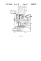
- FIG. 4 is a fragmentary sectional view of a centrifugal clutch mounted on a compressor.
- FIG. 5 is a fragmentary sectional view of an electric clutch which may be used in accordance with the principles of the invention.
- FIG. 1 view a typical arrangement is shown in which an engine 10, or alternatively an electric motor 12, may drive a compressor 14 in a transport refrigeration unit.
- an engine 10 or alternatively an electric motor 12
- its output is transmitted through the clutch 16 and belt 18 to drive the compressor.
- the clutch 16 is disengaged and the compressor 14 is driven directly through belt 20 from the motor 12, while the clutch drum free-wheels.
- FIG. 2 details of a typical centrifugal clutch driven by the engine output 22 are shown.
- the clutch shoe carrier part 24 of the clutch is driven by the engine output 22 to which it is directly attached.
- the drum part 26 of the clutch is supported from the hub 28 through bearing means which include an inner race 30, an outer race 32, and the ball bearings 34.
- a clutch 36 is compressor mounted and a rigid pulley 38 is engine mounted and a rigid pulley 40 is mounted on the output of the electric motor.
- a centrifugal clutch 36 in its mounting arrangement relative to the compressor is shown in FIG. 4.
- the stationary compressor seal plate 42 supports a bearing assembly including an inner race 44, an outer race 46, and intervening ball bearings 48, the bearing means in turn supporting the first pulley 50 which is connected through belt means 52 to be driven from the engine.
- the pulley 50 carries the conventional centrifugally movable shoes 54 which pivot radially outwardly when the pulley 50 rotates at or above a given speed.
- the centrifugal clutch of FIG. 4 also includes a second clutch pulley 56 which is adapted to be driven from the electric motor 12 through belt 58 and is directly attached to the compressor shaft 60 and includes a drum part 62 which is contacted by the shoes 54 when the clutch is in an engaged condition.
- the compressor-mounted clutch 36 also benefits from the torsional shock isolation provided by the resilient belt 52 between the engine 10 and the compressor 14. A substantial portion of the torsional oscillation and vibration experienced by the engine-mounted clutch of the prior art in FIG. 1 is absorbed through the belt 52 before exposure to the compressor-mounted clutch.
- the shoes 54 in the compressor-mounted clutch also enjoy further isolation from engine torque oscillation by the flywheel inertia of the engine-driven-shoe-carrier pulley 50.
- the benefits of the invention are also available with an electrically operated clutch 64 as shown in FIG. 5.
- the electric clutch itself is conventional and includes a field coil 66 which is stationary and mounted to the compressor body 42 and fits in a recess of the engine rotatable first pulley 68 which is rotatably supported from the compressor body 42 through the bearing assembly 70.
- the motor driven pulley 72 is fixedly attached to the compressor shaft 60 and carries the spring attached armature 74 which is adapted to be drawn toward the field coil 66 when the coil is energized, to lock the pulleys 68 and 72 together.
Landscapes
- Engineering & Computer Science (AREA)
- General Engineering & Computer Science (AREA)
- Physics & Mathematics (AREA)
- Mechanical Engineering (AREA)
- Thermal Sciences (AREA)
- Electromagnetism (AREA)
- Pulleys (AREA)
- One-Way And Automatic Clutches, And Combinations Of Different Clutches (AREA)
Abstract
Description
Claims (3)
Priority Applications (1)
| Application Number | Priority Date | Filing Date | Title |
|---|---|---|---|
| US06/741,089 US4846327A (en) | 1985-06-04 | 1985-06-04 | Drive arrangement for compressor of a transport refrigeration unit |
Applications Claiming Priority (1)
| Application Number | Priority Date | Filing Date | Title |
|---|---|---|---|
| US06/741,089 US4846327A (en) | 1985-06-04 | 1985-06-04 | Drive arrangement for compressor of a transport refrigeration unit |
Related Parent Applications (1)
| Application Number | Title | Priority Date | Filing Date |
|---|---|---|---|
| US06641093 Continuation | 1984-08-15 |
Related Child Applications (1)
| Application Number | Title | Priority Date | Filing Date |
|---|---|---|---|
| US06807194 Continuation | 1985-12-09 |
Publications (1)
| Publication Number | Publication Date |
|---|---|
| US4846327A true US4846327A (en) | 1989-07-11 |
Family
ID=24979348
Family Applications (1)
| Application Number | Title | Priority Date | Filing Date |
|---|---|---|---|
| US06/741,089 Expired - Lifetime US4846327A (en) | 1985-06-04 | 1985-06-04 | Drive arrangement for compressor of a transport refrigeration unit |
Country Status (1)
| Country | Link |
|---|---|
| US (1) | US4846327A (en) |
Cited By (19)
| Publication number | Priority date | Publication date | Assignee | Title |
|---|---|---|---|---|
| US5249429A (en) * | 1993-02-08 | 1993-10-05 | Thermo King Corporation | Methods of operating a refrigeration system |
| US5252874A (en) * | 1992-11-20 | 1993-10-12 | Thermo King Corporation | Electromagnetic clutch with torque isolation for return springs |
| US5989151A (en) * | 1998-08-11 | 1999-11-23 | Siemens Canada Limited | Hybrid engine cooling system having electric motor with electro-magnetic clutch |
| FR2818340A1 (en) * | 2000-12-20 | 2002-06-21 | Denso Corp | ELECTROMAGNETIC CLUTCH |
| US6659727B2 (en) * | 2001-09-07 | 2003-12-09 | General Motors Corporation | Control method for a dual mode compressor drive system |
| US6796367B2 (en) * | 2001-08-13 | 2004-09-28 | Inventive Technologies Foundation | Vehicle battery charging and air conditioning operating unit |
| US20050215366A1 (en) * | 2004-03-24 | 2005-09-29 | Alexander Serkh | Dual ratio belt drive system |
| US20060207274A1 (en) * | 2005-03-14 | 2006-09-21 | Harris Warner O | Fuel cell-driven auxiliary system, and method therefor |
| US20080017468A1 (en) * | 2006-07-21 | 2008-01-24 | Linnig Trucktec Gmbh | Drive member for water pump |
| US7600595B2 (en) | 2005-03-14 | 2009-10-13 | Zero Emission Systems, Inc. | Electric traction |
| US7921945B2 (en) | 2006-02-21 | 2011-04-12 | Clean Emissions Technologies, Inc. | Vehicular switching, including switching traction modes and shifting gears while in electric traction mode |
| US7921950B2 (en) | 2006-11-10 | 2011-04-12 | Clean Emissions Technologies, Inc. | Electric traction retrofit |
| US8565969B2 (en) | 2007-04-03 | 2013-10-22 | Clean Emissions Technologies, Inc. | Over the road/traction/cabin comfort retrofit |
| US8668035B2 (en) | 2006-03-14 | 2014-03-11 | Clean Emissions Technologies, Inc. | Electric traction system and method |
| US9631528B2 (en) | 2009-09-03 | 2017-04-25 | Clean Emissions Technologies, Inc. | Vehicle reduced emission deployment |
| US9758146B2 (en) | 2008-04-01 | 2017-09-12 | Clean Emissions Technologies, Inc. | Dual mode clutch pedal for vehicle |
| WO2019102451A1 (en) * | 2017-11-27 | 2019-05-31 | Farhi Robby | Battery charging and vehicle air conditioning auxiliary systems |
| DE102020006374A1 (en) * | 2020-10-16 | 2021-04-15 | Daimler Ag | Air conditioning device for a motor vehicle and motor vehicle with such an air conditioning device |
| US11441479B2 (en) * | 2016-05-27 | 2022-09-13 | Cummins Inc. | Prime mover systems including multi-accessory drives and methods of controlling same |
Citations (18)
| Publication number | Priority date | Publication date | Assignee | Title |
|---|---|---|---|---|
| GB475849A (en) * | 1936-03-20 | 1937-11-26 | Fusion Moteurs Manufacturers | Clutch, especially for centrifuges |
| US2513798A (en) * | 1947-04-28 | 1950-07-04 | Milton L Hatfield | Centrifugal clutch |
| US2639794A (en) * | 1950-05-26 | 1953-05-26 | Gen Electric | Drive clutch for washing machines or the like |
| US2975614A (en) * | 1958-01-08 | 1961-03-21 | Tranter Mfg Inc | Mobile refrigeration system |
| US3208571A (en) * | 1960-01-04 | 1965-09-28 | Bochory Michael | Centrifugally operated clutch mechanism |
| US3426877A (en) * | 1967-02-13 | 1969-02-11 | Frank F Cancilla Jr | Centrifugal axle clutch |
| US3512373A (en) * | 1968-07-12 | 1970-05-19 | Transicold Corp | Refrigeration system with electric auxiliary prime mover |
| US3545222A (en) * | 1968-10-14 | 1970-12-08 | Trane Co | Dual powered refrigeration system |
| DE2123749A1 (en) * | 1971-05-13 | 1972-11-23 | Robert Bosch Gmbh, 7000 Stuttgart | Coupling device for power transmission between a drive and a pump |
| US3718214A (en) * | 1971-05-04 | 1973-02-27 | Textron Inc | Centrifugal clutch |
| US3789618A (en) * | 1972-08-14 | 1974-02-05 | J Feliz | Auxiliary drive for engine driven air conditioner |
| US3842378A (en) * | 1973-07-20 | 1974-10-15 | Pitts Ind Inc | Double clutch for vehicle air conditioning compressor |
| US3844130A (en) * | 1973-07-09 | 1974-10-29 | M Wahnish | Automobile air conditioning system employing auxiliary prime motor |
| DE2341208A1 (en) * | 1973-08-16 | 1975-02-20 | Zahnradfabrik Friedrichshafen | ELECTROMAGNET SINGLE SURFACE DOUBLE COUPLING |
| JPS51914A (en) * | 1974-06-12 | 1976-01-07 | Ibm | |
| SU573641A1 (en) * | 1976-03-04 | 1977-09-25 | Предприятие П/Я В-2203 | Electromagnetic clutch |
| US4488627A (en) * | 1980-09-03 | 1984-12-18 | Suddeutsche Kuhlerfabrik Julius Fr. Behr Gmbh & Co. Kg | Electromagnetic two-stage clutch |
| US4567975A (en) * | 1984-02-17 | 1986-02-04 | Warner Electric Brake & Clutch Co. | Apparatus and method for controlling the engagement of a gap-type electromagnetic coupling and for alleviating engagement noise |
-
1985
- 1985-06-04 US US06/741,089 patent/US4846327A/en not_active Expired - Lifetime
Patent Citations (18)
| Publication number | Priority date | Publication date | Assignee | Title |
|---|---|---|---|---|
| GB475849A (en) * | 1936-03-20 | 1937-11-26 | Fusion Moteurs Manufacturers | Clutch, especially for centrifuges |
| US2513798A (en) * | 1947-04-28 | 1950-07-04 | Milton L Hatfield | Centrifugal clutch |
| US2639794A (en) * | 1950-05-26 | 1953-05-26 | Gen Electric | Drive clutch for washing machines or the like |
| US2975614A (en) * | 1958-01-08 | 1961-03-21 | Tranter Mfg Inc | Mobile refrigeration system |
| US3208571A (en) * | 1960-01-04 | 1965-09-28 | Bochory Michael | Centrifugally operated clutch mechanism |
| US3426877A (en) * | 1967-02-13 | 1969-02-11 | Frank F Cancilla Jr | Centrifugal axle clutch |
| US3512373A (en) * | 1968-07-12 | 1970-05-19 | Transicold Corp | Refrigeration system with electric auxiliary prime mover |
| US3545222A (en) * | 1968-10-14 | 1970-12-08 | Trane Co | Dual powered refrigeration system |
| US3718214A (en) * | 1971-05-04 | 1973-02-27 | Textron Inc | Centrifugal clutch |
| DE2123749A1 (en) * | 1971-05-13 | 1972-11-23 | Robert Bosch Gmbh, 7000 Stuttgart | Coupling device for power transmission between a drive and a pump |
| US3789618A (en) * | 1972-08-14 | 1974-02-05 | J Feliz | Auxiliary drive for engine driven air conditioner |
| US3844130A (en) * | 1973-07-09 | 1974-10-29 | M Wahnish | Automobile air conditioning system employing auxiliary prime motor |
| US3842378A (en) * | 1973-07-20 | 1974-10-15 | Pitts Ind Inc | Double clutch for vehicle air conditioning compressor |
| DE2341208A1 (en) * | 1973-08-16 | 1975-02-20 | Zahnradfabrik Friedrichshafen | ELECTROMAGNET SINGLE SURFACE DOUBLE COUPLING |
| JPS51914A (en) * | 1974-06-12 | 1976-01-07 | Ibm | |
| SU573641A1 (en) * | 1976-03-04 | 1977-09-25 | Предприятие П/Я В-2203 | Electromagnetic clutch |
| US4488627A (en) * | 1980-09-03 | 1984-12-18 | Suddeutsche Kuhlerfabrik Julius Fr. Behr Gmbh & Co. Kg | Electromagnetic two-stage clutch |
| US4567975A (en) * | 1984-02-17 | 1986-02-04 | Warner Electric Brake & Clutch Co. | Apparatus and method for controlling the engagement of a gap-type electromagnetic coupling and for alleviating engagement noise |
Cited By (26)
| Publication number | Priority date | Publication date | Assignee | Title |
|---|---|---|---|---|
| US5252874A (en) * | 1992-11-20 | 1993-10-12 | Thermo King Corporation | Electromagnetic clutch with torque isolation for return springs |
| US5249429A (en) * | 1993-02-08 | 1993-10-05 | Thermo King Corporation | Methods of operating a refrigeration system |
| US5989151A (en) * | 1998-08-11 | 1999-11-23 | Siemens Canada Limited | Hybrid engine cooling system having electric motor with electro-magnetic clutch |
| FR2818340A1 (en) * | 2000-12-20 | 2002-06-21 | Denso Corp | ELECTROMAGNETIC CLUTCH |
| US6796367B2 (en) * | 2001-08-13 | 2004-09-28 | Inventive Technologies Foundation | Vehicle battery charging and air conditioning operating unit |
| US6659727B2 (en) * | 2001-09-07 | 2003-12-09 | General Motors Corporation | Control method for a dual mode compressor drive system |
| US20050215366A1 (en) * | 2004-03-24 | 2005-09-29 | Alexander Serkh | Dual ratio belt drive system |
| US7798928B2 (en) * | 2004-03-24 | 2010-09-21 | The Gates Corporation | Dual ratio belt drive system |
| US20060207274A1 (en) * | 2005-03-14 | 2006-09-21 | Harris Warner O | Fuel cell-driven auxiliary system, and method therefor |
| US8286440B2 (en) | 2005-03-14 | 2012-10-16 | Clean Emissions Technologies, Inc. | Operating a comfort subsystem for a vehicle |
| US7543454B2 (en) | 2005-03-14 | 2009-06-09 | Zero Emission Systems, Inc. | Method and auxiliary system for operating a comfort subsystem for a vehicle |
| US7600595B2 (en) | 2005-03-14 | 2009-10-13 | Zero Emission Systems, Inc. | Electric traction |
| US7921945B2 (en) | 2006-02-21 | 2011-04-12 | Clean Emissions Technologies, Inc. | Vehicular switching, including switching traction modes and shifting gears while in electric traction mode |
| US8668035B2 (en) | 2006-03-14 | 2014-03-11 | Clean Emissions Technologies, Inc. | Electric traction system and method |
| US9457792B2 (en) | 2006-03-14 | 2016-10-04 | Clean Emissions Technologies, Inc. | Retrofitting a vehicle drive train |
| US20080017468A1 (en) * | 2006-07-21 | 2008-01-24 | Linnig Trucktec Gmbh | Drive member for water pump |
| US7921950B2 (en) | 2006-11-10 | 2011-04-12 | Clean Emissions Technologies, Inc. | Electric traction retrofit |
| US8565969B2 (en) | 2007-04-03 | 2013-10-22 | Clean Emissions Technologies, Inc. | Over the road/traction/cabin comfort retrofit |
| US9707861B2 (en) | 2008-03-19 | 2017-07-18 | Clean Emissions Technologies, Inc. | Data acquisition for operation of a vehicle |
| US9758146B2 (en) | 2008-04-01 | 2017-09-12 | Clean Emissions Technologies, Inc. | Dual mode clutch pedal for vehicle |
| US9631528B2 (en) | 2009-09-03 | 2017-04-25 | Clean Emissions Technologies, Inc. | Vehicle reduced emission deployment |
| US11441479B2 (en) * | 2016-05-27 | 2022-09-13 | Cummins Inc. | Prime mover systems including multi-accessory drives and methods of controlling same |
| US11781475B2 (en) | 2016-05-27 | 2023-10-10 | Cummins Inc. | Prime mover systems including multi-accessory drives and methods of controlling same |
| WO2019102451A1 (en) * | 2017-11-27 | 2019-05-31 | Farhi Robby | Battery charging and vehicle air conditioning auxiliary systems |
| US11970046B1 (en) | 2017-11-27 | 2024-04-30 | Robby FARHI | Computerized vehicle controller and routing method for a vehicle |
| DE102020006374A1 (en) * | 2020-10-16 | 2021-04-15 | Daimler Ag | Air conditioning device for a motor vehicle and motor vehicle with such an air conditioning device |
Similar Documents
| Publication | Publication Date | Title |
|---|---|---|
| US4846327A (en) | Drive arrangement for compressor of a transport refrigeration unit | |
| US4926992A (en) | Electromagnetically operable friction-disk clutch | |
| JP2761191B2 (en) | Belt transmission method and belt transmission device | |
| US3941012A (en) | Dual drive mechanism | |
| EP0204190B1 (en) | Drive arrangement for compressor of a transport refrigeration unit | |
| US4227861A (en) | Cooling fan with viscous-magnetic fan clutch | |
| JP3567769B2 (en) | Rotating device and electromagnetic clutch | |
| EP0308829B1 (en) | Torque variation absorbing device | |
| JPS58151846A (en) | 3-phase generator | |
| US4517482A (en) | Vehicular-type alternator with speed-responsive fan coupling | |
| EP0012815B1 (en) | Acceleration responsive clutch | |
| GB2096237A (en) | Isolation of auxiliary-device drive belt from torsional vibrations of an I.C. engine | |
| US4589855A (en) | Forced air-cooled vehicular-type alternator | |
| JPS61229970A (en) | engine with starter | |
| JPS6363780B2 (en) | ||
| WO1996008642A1 (en) | Apparatus for driving alternator of engine, and alternator for engine accessoires used therefor | |
| JPS61233252A (en) | Belt-driven power transmission device | |
| JPH0533785Y2 (en) | ||
| JPS5810607B2 (en) | electromagnetic clutch | |
| JPH0417870Y2 (en) | ||
| JPH1061439A (en) | Liquid circulation device for vehicle power source | |
| JPS6363779B2 (en) | ||
| JPH0533784Y2 (en) | ||
| JPS5924007B2 (en) | Power extraction mechanism for vehicle cooling system | |
| JP4400472B2 (en) | Power transmission device for internal combustion engine |
Legal Events
| Date | Code | Title | Description |
|---|---|---|---|
| AS | Assignment |
Owner name: THERMO KING CORPORATION, 914 W. 90TH STREET, MINNE Free format text: ASSIGNMENT OF ASSIGNORS INTEREST.;ASSIGNOR:MAYER, DONALD K.;REEL/FRAME:004414/0198 Effective date: 19850529 |
|
| STCF | Information on status: patent grant |
Free format text: PATENTED CASE |
|
| FEPP | Fee payment procedure |
Free format text: PAYOR NUMBER ASSIGNED (ORIGINAL EVENT CODE: ASPN); ENTITY STATUS OF PATENT OWNER: LARGE ENTITY |
|
| FPAY | Fee payment |
Year of fee payment: 4 |
|
| FPAY | Fee payment |
Year of fee payment: 8 |
|
| FEPP | Fee payment procedure |
Free format text: PAYER NUMBER DE-ASSIGNED (ORIGINAL EVENT CODE: RMPN); ENTITY STATUS OF PATENT OWNER: LARGE ENTITY Free format text: PAYOR NUMBER ASSIGNED (ORIGINAL EVENT CODE: ASPN); ENTITY STATUS OF PATENT OWNER: LARGE ENTITY |
|
| FPAY | Fee payment |
Year of fee payment: 12 |