US4839030A - Coal liquefaction process utilizing coal/CO2 slurry feedstream - Google Patents
Coal liquefaction process utilizing coal/CO2 slurry feedstream Download PDFInfo
- Publication number
- US4839030A US4839030A US07/199,493 US19949388A US4839030A US 4839030 A US4839030 A US 4839030A US 19949388 A US19949388 A US 19949388A US 4839030 A US4839030 A US 4839030A
- Authority
- US
- United States
- Prior art keywords
- coal
- reactor
- liquid
- slurry
- hydrogen
- Prior art date
- Legal status (The legal status is an assumption and is not a legal conclusion. Google has not performed a legal analysis and makes no representation as to the accuracy of the status listed.)
- Expired - Lifetime
Links
- 239000003245 coal Substances 0.000 title claims abstract description 234
- 239000002002 slurry Substances 0.000 title claims abstract description 67
- 238000000034 method Methods 0.000 title claims abstract description 49
- 230000008569 process Effects 0.000 title claims abstract description 46
- 239000007788 liquid Substances 0.000 claims abstract description 112
- UFHFLCQGNIYNRP-UHFFFAOYSA-N Hydrogen Chemical compound [H][H] UFHFLCQGNIYNRP-UHFFFAOYSA-N 0.000 claims abstract description 68
- 239000001257 hydrogen Substances 0.000 claims abstract description 62
- 229910052739 hydrogen Inorganic materials 0.000 claims abstract description 62
- 229930195733 hydrocarbon Natural products 0.000 claims abstract description 56
- 150000002430 hydrocarbons Chemical class 0.000 claims abstract description 56
- 239000004215 Carbon black (E152) Substances 0.000 claims abstract description 53
- 239000007789 gas Substances 0.000 claims abstract description 45
- 238000005984 hydrogenation reaction Methods 0.000 claims abstract description 32
- 239000002245 particle Substances 0.000 claims abstract description 22
- 239000012263 liquid product Substances 0.000 claims abstract description 18
- 230000009969 flowable effect Effects 0.000 claims abstract description 16
- 238000006555 catalytic reaction Methods 0.000 claims abstract description 10
- CURLTUGMZLYLDI-UHFFFAOYSA-N Carbon dioxide Chemical compound O=C=O CURLTUGMZLYLDI-UHFFFAOYSA-N 0.000 claims description 125
- 229910002092 carbon dioxide Inorganic materials 0.000 claims description 113
- 238000006243 chemical reaction Methods 0.000 claims description 57
- 239000003054 catalyst Substances 0.000 claims description 46
- 239000000463 material Substances 0.000 claims description 27
- 238000002156 mixing Methods 0.000 claims description 22
- 238000009835 boiling Methods 0.000 claims description 12
- 239000001569 carbon dioxide Substances 0.000 claims description 12
- 239000000047 product Substances 0.000 claims description 12
- VYPSYNLAJGMNEJ-UHFFFAOYSA-N Silicium dioxide Chemical compound O=[Si]=O VYPSYNLAJGMNEJ-UHFFFAOYSA-N 0.000 claims description 8
- 150000002431 hydrogen Chemical class 0.000 claims description 6
- PNEYBMLMFCGWSK-UHFFFAOYSA-N aluminium oxide Inorganic materials [O-2].[O-2].[O-2].[Al+3].[Al+3] PNEYBMLMFCGWSK-UHFFFAOYSA-N 0.000 claims description 5
- 239000000203 mixture Substances 0.000 claims description 5
- 238000004064 recycling Methods 0.000 claims description 5
- XEEYBQQBJWHFJM-UHFFFAOYSA-N Iron Chemical compound [Fe] XEEYBQQBJWHFJM-UHFFFAOYSA-N 0.000 claims description 4
- CPLXHLVBOLITMK-UHFFFAOYSA-N Magnesium oxide Chemical compound [Mg]=O CPLXHLVBOLITMK-UHFFFAOYSA-N 0.000 claims description 4
- PXHVJJICTQNCMI-UHFFFAOYSA-N Nickel Chemical compound [Ni] PXHVJJICTQNCMI-UHFFFAOYSA-N 0.000 claims description 4
- GWEVSGVZZGPLCZ-UHFFFAOYSA-N Titan oxide Chemical compound O=[Ti]=O GWEVSGVZZGPLCZ-UHFFFAOYSA-N 0.000 claims description 4
- 238000001704 evaporation Methods 0.000 claims description 4
- 230000008020 evaporation Effects 0.000 claims description 4
- 239000000377 silicon dioxide Substances 0.000 claims description 4
- 150000002739 metals Chemical group 0.000 claims description 3
- ZOKXTWBITQBERF-UHFFFAOYSA-N Molybdenum Chemical compound [Mo] ZOKXTWBITQBERF-UHFFFAOYSA-N 0.000 claims description 2
- ATJFFYVFTNAWJD-UHFFFAOYSA-N Tin Chemical compound [Sn] ATJFFYVFTNAWJD-UHFFFAOYSA-N 0.000 claims description 2
- 229910017052 cobalt Inorganic materials 0.000 claims description 2
- 239000010941 cobalt Substances 0.000 claims description 2
- GUTLYIVDDKVIGB-UHFFFAOYSA-N cobalt atom Chemical compound [Co] GUTLYIVDDKVIGB-UHFFFAOYSA-N 0.000 claims description 2
- 229910052742 iron Inorganic materials 0.000 claims description 2
- 239000000395 magnesium oxide Substances 0.000 claims description 2
- 150000002736 metal compounds Chemical class 0.000 claims description 2
- 229910044991 metal oxide Inorganic materials 0.000 claims description 2
- 150000004706 metal oxides Chemical class 0.000 claims description 2
- 229910052750 molybdenum Inorganic materials 0.000 claims description 2
- 239000011733 molybdenum Substances 0.000 claims description 2
- 229910052759 nickel Inorganic materials 0.000 claims description 2
- 239000011135 tin Substances 0.000 claims description 2
- 229910052718 tin Inorganic materials 0.000 claims description 2
- WFKWXMTUELFFGS-UHFFFAOYSA-N tungsten Chemical compound [W] WFKWXMTUELFFGS-UHFFFAOYSA-N 0.000 claims description 2
- 229910052721 tungsten Inorganic materials 0.000 claims description 2
- 239000010937 tungsten Substances 0.000 claims description 2
- XLYOFNOQVPJJNP-UHFFFAOYSA-N water Substances O XLYOFNOQVPJJNP-UHFFFAOYSA-N 0.000 claims description 2
- 239000002802 bituminous coal Substances 0.000 claims 1
- 230000003197 catalytic effect Effects 0.000 abstract description 31
- 239000002904 solvent Substances 0.000 description 21
- 239000007787 solid Substances 0.000 description 17
- 239000003921 oil Substances 0.000 description 11
- 238000010438 heat treatment Methods 0.000 description 9
- WYURNTSHIVDZCO-UHFFFAOYSA-N Tetrahydrofuran Chemical compound C1CCOC1 WYURNTSHIVDZCO-UHFFFAOYSA-N 0.000 description 8
- 238000009903 catalytic hydrogenation reaction Methods 0.000 description 7
- 150000001875 compounds Chemical class 0.000 description 7
- 230000015572 biosynthetic process Effects 0.000 description 6
- 238000005755 formation reaction Methods 0.000 description 6
- 125000005842 heteroatom Chemical group 0.000 description 6
- 238000000926 separation method Methods 0.000 description 6
- 239000000571 coke Substances 0.000 description 5
- 238000004821 distillation Methods 0.000 description 5
- VNWKTOKETHGBQD-UHFFFAOYSA-N methane Chemical compound C VNWKTOKETHGBQD-UHFFFAOYSA-N 0.000 description 5
- 229910052760 oxygen Inorganic materials 0.000 description 5
- 239000001301 oxygen Substances 0.000 description 5
- IJGRMHOSHXDMSA-UHFFFAOYSA-N Atomic nitrogen Chemical compound N#N IJGRMHOSHXDMSA-UHFFFAOYSA-N 0.000 description 4
- QVGXLLKOCUKJST-UHFFFAOYSA-N atomic oxygen Chemical compound [O] QVGXLLKOCUKJST-UHFFFAOYSA-N 0.000 description 4
- 238000001816 cooling Methods 0.000 description 4
- 230000002028 premature Effects 0.000 description 4
- 238000000746 purification Methods 0.000 description 4
- BBEAQIROQSPTKN-UHFFFAOYSA-N pyrene Chemical compound C1=CC=C2C=CC3=CC=CC4=CC=C1C2=C43 BBEAQIROQSPTKN-UHFFFAOYSA-N 0.000 description 4
- YLQBMQCUIZJEEH-UHFFFAOYSA-N tetrahydrofuran Natural products C=1C=COC=1 YLQBMQCUIZJEEH-UHFFFAOYSA-N 0.000 description 4
- 229910052770 Uranium Inorganic materials 0.000 description 3
- 125000003118 aryl group Chemical group 0.000 description 3
- 239000003250 coal slurry Substances 0.000 description 3
- 230000000694 effects Effects 0.000 description 3
- 230000006872 improvement Effects 0.000 description 3
- 229910052500 inorganic mineral Inorganic materials 0.000 description 3
- 239000011707 mineral Substances 0.000 description 3
- 238000006116 polymerization reaction Methods 0.000 description 3
- 239000003507 refrigerant Substances 0.000 description 3
- 238000004517 catalytic hydrocracking Methods 0.000 description 2
- KYYSIVCCYWZZLR-UHFFFAOYSA-N cobalt(2+);dioxido(dioxo)molybdenum Chemical compound [Co+2].[O-][Mo]([O-])(=O)=O KYYSIVCCYWZZLR-UHFFFAOYSA-N 0.000 description 2
- 238000002485 combustion reaction Methods 0.000 description 2
- 239000012809 cooling fluid Substances 0.000 description 2
- 238000005336 cracking Methods 0.000 description 2
- 230000009849 deactivation Effects 0.000 description 2
- 238000010586 diagram Methods 0.000 description 2
- NLPVCCRZRNXTLT-UHFFFAOYSA-N dioxido(dioxo)molybdenum;nickel(2+) Chemical compound [Ni+2].[O-][Mo]([O-])(=O)=O NLPVCCRZRNXTLT-UHFFFAOYSA-N 0.000 description 2
- 239000000386 donor Substances 0.000 description 2
- 239000012530 fluid Substances 0.000 description 2
- GVEPBJHOBDJJJI-UHFFFAOYSA-N fluoranthrene Natural products C1=CC(C2=CC=CC=C22)=C3C2=CC=CC3=C1 GVEPBJHOBDJJJI-UHFFFAOYSA-N 0.000 description 2
- 238000000227 grinding Methods 0.000 description 2
- 239000000852 hydrogen donor Substances 0.000 description 2
- MOWMLACGTDMJRV-UHFFFAOYSA-N nickel tungsten Chemical compound [Ni].[W] MOWMLACGTDMJRV-UHFFFAOYSA-N 0.000 description 2
- 229910052757 nitrogen Inorganic materials 0.000 description 2
- 238000005086 pumping Methods 0.000 description 2
- -1 pyrene/hydropyrenes Chemical class 0.000 description 2
- 230000001373 regressive effect Effects 0.000 description 2
- 238000003303 reheating Methods 0.000 description 2
- 150000003464 sulfur compounds Chemical class 0.000 description 2
- 230000000153 supplemental effect Effects 0.000 description 2
- 238000009834 vaporization Methods 0.000 description 2
- 230000008016 vaporization Effects 0.000 description 2
- OKTJSMMVPCPJKN-UHFFFAOYSA-N Carbon Chemical compound [C] OKTJSMMVPCPJKN-UHFFFAOYSA-N 0.000 description 1
- 150000001298 alcohols Chemical class 0.000 description 1
- 229910052799 carbon Inorganic materials 0.000 description 1
- 230000000052 comparative effect Effects 0.000 description 1
- 238000006356 dehydrogenation reaction Methods 0.000 description 1
- 230000001419 dependent effect Effects 0.000 description 1
- 238000011143 downstream manufacturing Methods 0.000 description 1
- 230000009977 dual effect Effects 0.000 description 1
- 150000004675 formic acid derivatives Chemical class 0.000 description 1
- 150000002596 lactones Chemical class 0.000 description 1
- 239000003077 lignite Substances 0.000 description 1
- 229910052751 metal Inorganic materials 0.000 description 1
- 239000002184 metal Substances 0.000 description 1
- 238000012986 modification Methods 0.000 description 1
- 230000004048 modification Effects 0.000 description 1
- 238000002360 preparation method Methods 0.000 description 1
- 230000009257 reactivity Effects 0.000 description 1
- 238000011084 recovery Methods 0.000 description 1
- 230000009467 reduction Effects 0.000 description 1
- 239000002195 soluble material Substances 0.000 description 1
- 238000011144 upstream manufacturing Methods 0.000 description 1
- 238000005292 vacuum distillation Methods 0.000 description 1
Images


Classifications
-
- C—CHEMISTRY; METALLURGY
- C10—PETROLEUM, GAS OR COKE INDUSTRIES; TECHNICAL GASES CONTAINING CARBON MONOXIDE; FUELS; LUBRICANTS; PEAT
- C10G—CRACKING HYDROCARBON OILS; PRODUCTION OF LIQUID HYDROCARBON MIXTURES, e.g. BY DESTRUCTIVE HYDROGENATION, OLIGOMERISATION, POLYMERISATION; RECOVERY OF HYDROCARBON OILS FROM OIL-SHALE, OIL-SAND, OR GASES; REFINING MIXTURES MAINLY CONSISTING OF HYDROCARBONS; REFORMING OF NAPHTHA; MINERAL WAXES
- C10G1/00—Production of liquid hydrocarbon mixtures from oil-shale, oil-sand, or non-melting solid carbonaceous or similar materials, e.g. wood, coal
- C10G1/08—Production of liquid hydrocarbon mixtures from oil-shale, oil-sand, or non-melting solid carbonaceous or similar materials, e.g. wood, coal with moving catalysts
- C10G1/083—Production of liquid hydrocarbon mixtures from oil-shale, oil-sand, or non-melting solid carbonaceous or similar materials, e.g. wood, coal with moving catalysts in the presence of a solvent
-
- Y—GENERAL TAGGING OF NEW TECHNOLOGICAL DEVELOPMENTS; GENERAL TAGGING OF CROSS-SECTIONAL TECHNOLOGIES SPANNING OVER SEVERAL SECTIONS OF THE IPC; TECHNICAL SUBJECTS COVERED BY FORMER USPC CROSS-REFERENCE ART COLLECTIONS [XRACs] AND DIGESTS
- Y10—TECHNICAL SUBJECTS COVERED BY FORMER USPC
- Y10S—TECHNICAL SUBJECTS COVERED BY FORMER USPC CROSS-REFERENCE ART COLLECTIONS [XRACs] AND DIGESTS
- Y10S208/00—Mineral oils: processes and products
- Y10S208/952—Solid feed treatment under supercritical conditions
Definitions
- This invention pertains to an improved coal liquefaction process in which particulate coal is slurried with liquid carbon dioxide to provide a flowable feedstream. It pertains particularly to a coal hydrogenation and liquefaction process in which pressurized particulate coal feed is slurried with liquid carbon dioxide, before being further pressurized and fed into a catalytic reactor for producing hydrocarbon gas and liquid products.
- coal feed in particulate form is conventionally slurried with a hydrocarbon liquid such as recycled solvent oil and then pressurized sufficiently to feed the coal/oil slurry into a catalytic reactor operated at high temperature and pressure conditions.
- a hydrocarbon liquid such as recycled solvent oil
- Examples of such coal liquefaction processes are disclosed by U.S. Pat. No. 3,519,555 to Keith et al, U.S. Pat. No. 3,617,465 to Wolk et al, U.S. Pat. No. 3,700,584 to Johanson et al, and U.S. Pat. No. 4,437,973 to Huibers et al.
- the present invention provides an improved process for the hydrogenation and liquefaction of coal to produce hydrocarbon liquid and gas products, and provides for slurrying substantially dry particulate coal with liquid carbon dioxide at a temperature below its critical temperature and at an intermediate pressure, then pumping the coal/CO 2 liquid slurry feedstream at its low temperature into a catalytic ebullated bed reaction zone. Any supplemental heat needed for the exothermic hydrogenation reactions in the reaction zone is provided via a heated hydrogen feed stream, and/or by heating the reactor liquid recycled to the ebullated bed reactor.
- the process utilizes a feedstream of particulate coal slurried with sufficient liquid CO 2 to provide a flowable mixture.
- the coal having particle size of 50-325 mesh (U.S.
- the coal/CO 2 slurry can be cooled to some extent either by cooling the slurry mixing tank using a refrigerant, or by controlled evaporation of a portion of the liquid CO 2 from the slurry during handling.
- the resulting coal/CO 2 slurry at temperature below about 85° F. is further pressurized to at least about 1000 psig and fed into a mixing chamber, such as the lower plenum of a reactor containing an ebullated catalyst bed. Heated hydrogen gas is fed separately into the reactor plenum mixing chamber, where the coal and CO 2 are mixed with the heated hydrogen gas and recycled reactor liquid. The CO 2 is at least partially evaporated from the slurry, while the coal and recycled reactor liquid are passed upwardly through a flow distributor into the catalyst bed, which is maintained at temperature of 650°-850° F. Because of the need for maintaining temperatures for the coal/CO 2 slurry feed stream below about 85° F.
- the desired temperature and heat of reaction in the reactor are maintained either by heating the hydrogen gas feed stream to a temperature somewhat above the catalyst bed temperature, or by heating the recycled reactor liquid used for maintaining catalyst bed ebullation, or both.
- the liquid CO 2 contained in the coal/CO 2 slurry feedstream is rapidly heated and evaporated, which contributes to further fracturing of the coal particles without fracturing the mineral matter, and facilitates separation of the mineral matter contained in the coal.
- the CO 2 participates in the reaction via hydrogen reduction to form methane, hydrocarbons, alcohols, formates, lactones and other oxygenates and compounds.
- the CO 2 as a consequance of its reactivity and mole fraction, will have a minimal effect on hydrogen partial pressure in the reactor.
- Sufficient hydrocarbon solvent liquid is usually internally-generated from the coal feed to provide adequate liquid recycle and back-mixing of the coal feed and catalyst in the ebullated bed reaction zone.
- the coal/CO 2 slurry is fed into the catalytic reaction zone, which is maintained at selected moderate temperature and pressure conditions and in the presence of a particulate hydrogenation catalyst which promotes controlled rate hydrogenation and liquefaction of the coal, while simultaneously hydrogenating the recycle solvent oils at conditions which favor hydrogenation reactions.
- the reaction zone contains an ebullated bed of a particulate hydrogenation catalyst to hydrogenate the aromatic rings in the coal, recycle solvent and dissolved coal molecules, and produces the desired low-boiling hydrocarbon liquid and gaseous product materials.
- Useful reaction conditions are 650°-850° F. temperature and 1000-4000 psig hydrogen partial pressure, with coal feed rate of 10-100 lb coal/ft 3 reactor volume.
- the catalyst used should contain an active metal oxide or other metal compound selected from the metals group consisting of cobalt, iron, molybdenum, nickel, tin, tungsten and other hydrocarbon hydrogenation catalyst metals known in the art, deposited on a base material selected from the group consisting of alumina, magnesia, silica, titania, and similar materials.
- Useful catalyst particle sizes can range from about 0.030 to 0.125 inch effective diameter.
- the concentration of CO 2 gas in the reaction zone will depend not only on the percentage of liquid CO 2 provided in the coal/CO 2 slurry feedstream, but also depend on the oxygen content of the coal feed. Coal having relatively large particle size will generally require a greater percentage of liquid CO 2 to provide a flowable coal/CO 2 slurry. Also, low rank sub-bituminous type coal and lignites usually contain 15-30 W % oxygen and generate more CO 2 in the reaction zone than bituminous coals which contain only about 6-10 W % oxygen. The concentration of the CO 2 in the reaction zone will usually vary from about 2 mole % for micronized bituminous coals (25-100 micron particle size) up to about 10 mole % for -100 mesh size (U.S.
- the quantity of CO 2 generated in the reaction zone from the oxygen contained in the coal feed is very dependent on the process severity, i.e. reaction zone temperature, hydrogen partial pressure and residence time and the organic oxygen bonding structure of the coal.
- the effluent material containing hydrocarbon gas and liquid fractions is phase separated.
- the resulting gas fraction is processed to recover and liquefy sufficient CO 2 for recycle to the coal slurrying step, and to recover hydrogen for recycle to the reactor.
- Off-gases from the process include CO 2 , CO, CH 4 , H 2 S, NH 3 and other light hydrocarbons.
- Recovery of CO 2 for recycle to the coal slurrying step need not be complete, and may contain other components such as CO and methane as supplemental hydrogen sources.
- the hydrocarbon liquid fraction is pressure-reduced and distilled to produce hydrocarbon gases and low boiling hydrocarbon distillate liquid products, and the remaining unconverted coal and mineral matter is removed from the process.
- this invention can be advantageously used for single stage catalytic reaction processes for liquefying coal, it is preferably used in a catalytic two-stage coal liquefaction process.
- the coal/CO 2 slurry at 500-950 psig pressure is further pressurized and fed into a first stage ebullated catalyst bed reactor maintained at conditions of 650°-800° F. temperature, 1000-4000 psig hydrogen partial pressure, and at 10-100 lb coal/hr ft 3 reactor feed rate or space velocity to produce a high quality hydrocarbon solvent material, while achieving at least about 50 W % conversion of the coal to tetrahydrofuran (THF) soluble materials.
- THF tetrahydrofuran
- Preferred first stage reaction conditions are 700°-790° F. temperature, 1500-3500 psig hydrogen partial pressure, and a coal space velocity of 15-75 lbs coal/hr ft 3 reactor, with the preferred conditions usually being specific to the type of coal being processed.
- the total effluent material containing hydrocarbon gases and liquid fractions is preferably passed with additional heated hydrogen directly to a close-coupled second stage catalytic reaction zone, where the material is further hydrogenated and hydrocracked at a temperature preferably at least about 25° F. higher than for the first stage reaction zone.
- Both stage reaction zones are upflow, back mixed ebullated bed catalytic reactors.
- operating conditions are preferably maintained at higher severity which promote more complete thermal conversion of the coal to liquids, hydroconversion of primary liquids to distillate products, and product quality improvement via heteroatoms removal, and with similar hydrogen partial pressure and a hydroconversion catalyst, such as cobalt-moly on alumina.
- Useful second stage reaction conditions are 750°-875° F. temperature, 1000-4000 psig hydrogen partial pressure and coal space velocity of 10-100 lb coal/hr ft 3 reactor volume to achieve at least about 90 W % conversion of the remaining reactive coal along with the asphaltene and preasphaltene compounds to lower boiling hydrocarbon materials, and the heteroatoms are further reduced to provide tetrahydrofuran (THF) soluble product materials.
- Preferred second stage reaction conditions are 800°-860° F. temperature, 1500-3500 psig hydrogen partial pressure, and coal space velocity of 15-75 lb/hr ft 3 reactor volume.
- an effluent stream containing hydrocarbon gas and liquid fractions is withdrawn and phase separated.
- the resulting gas fraction is treated to recover and liquefy sufficient CO 2 for recycle to the coal slurrying step, and to recover hydrogen for recycle to the reactor.
- the hydrocarbon liquid fraction is pressure-reduced and distilled to produce hydrocarbon gases and distillate liquid products, and any remaining unconverted coal and ash solids is withdrawn from the system.
- This invention advantageously provides a process for hydrogenation and liquefaction of coal which does not require recycle of any substantial quantity of hydrocarbon liquid for slurrying the coal feed, and thereby desirably reduces the size of the catalytic reactor(s) and downstream processing equipment required for a particular coal feed rate, and also facilitates the net yield of low-boiling hydrocarbon liquid products. It is also an attribute of this invention that the CO 2 contained in the coal slurry feedstream has only a minor effect on the hydrogen partial pressure in the reaction zone(s) and also the CO 2 gas has only a minor effect on reactor volume. The process is facilitated by the internally-generated hydrocarbon liquid solvent produced in the first stage back mixed catalytic ebullated bed reactor.
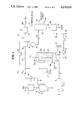
- FIG. 1 is a schematic flow diagram of a coal hydrogenation and liquefaction process according to the invention which utilizes a coal/CO 2 slurry feedstream into a single catalytic reactor;
- FIG. 2 is a partial pressure-enthalpy chart for carbon dioxide showing the required pressure-temperature relationships in the coal/CO 2 slurry mixing tank and catalytic reactor;
- FIG. 3 is a schematic diagram of a coal hydrogenation and liquefaction process utilizing an alternative flow arrangement for feeding the coal/CO 2 slurry feed stream into the first stage reactor of a two-stage catalytic hydrogenation process for producing low-boiling hydrocarbon gas and liquid products.
- a coal such as bituminous, sub-bituminous, or lignite is provided at 10 and passed to a preparation unit 12, where the coal is ground to a desired particle size range such as 50-375 mesh (U.S. Sieve Series), or finer and may be dried to a desired moisture content of 3-10 W % moisture remaining.
- the particulate coal is then passed through a suitable feeding device 14, such as a rotary feeder valve or dual lock hoppers, into a pressurized mixing tank 16 which is maintained at 500-1000 psig intermediate pressure.
- a suitable feeding device 14 such as a rotary feeder valve or dual lock hoppers
- the particulate coal is mixed with sufficient pressurized liquid CO 2 provided at 18 to produce a flowable coal/CO 2 slurry mixture.
- cooling the mixing tank 16 can be provided by a surrounding heat exchange jacket 17 adapted for circulating a refrigerant fluid through the jacket.
- the liquid CO 2 stream 18 is maintained at below its critical temperature of about 85° F., and preferably at 40°-80° F. and at pressure of 500 -1000 psig, as shown by the FIG. 2 pressureenthalpy chart, so as to cool the ground coal (which has usually been preheated to some extent by the grinding step), to the desired coal/CO 2 slurry temperature. At higher pressures, increased slurry temperatures are permitted as shown in the FIG. 2 chart.
- the CO 2 liquid effectively wets the coal particles to provide a flowable coal/CO 2 slurry containing at least about 50 W % coal, and preferably 60-85 W % coal concentration in the slurry.
- the resulting coal/CO 2 slurry 19 at intermediate pressure of 500-1000 psig is further pressurized by pump 20, in which the slurry is cooled during pressurization by a suitable cooling fluid flowing in pump jacket 20a, to prevent heating and premature vaporization of the CO 2 from the slurry feed stream 21 before it is introduced into the lower plenum 22 of catalytic reactor 24.
- Heated hydrogen gas at 23 is introduced separately into the reactor plenum 22.
- the coal/CO 2 slurry stream 21 is heated rapidly, and the CO 2 liquid is substantially evaporated while the particulate coal is mixed uniformly with the hydrogen gas 23 and with recycled reactor liquid, and all are passed uniformly upwardly through distribution grid plate 24a into the reactor ebullated catalyst bed 25.
- coal/CO 2 slurry feedstream 21 is usually not preheated before being introduced into catalytic reactor 24, at least a portion of the additional heat needed therein is provided by hydrogen stream 23 which can be heated at heater 27 to above the catalyst bed temperature.
- the reactor recycled liquid stream 28 which is withdrawn from above the catalyst bed 25 and recirculated by pump 29 can be heated at heater 30 to a temperature above the catalyst bed temperature before being reintroduced into plenum 22.
- Such rapid heating in plenum 22 of the coal particles which contains appreciable amounts of absorbed liquid CO 2 liquid causes the CO 2 to expand rapidly and fracture the coal particles.
- Such fracturing of the coal into finer particles facilitates its intimate contact with the hydrogen gas and coal derived solvent liquid, and contributes to catalytic hydrogenation and liquefaction of the coal. Also such fracturing of the coal facilitates separation of ash solids from the coal-derived hydrocarbon liquids.
- the coal/CO 2 slurry and hydrogen streams entering reactor 24 pass uniformly upwardly through flow distributor 24a and ebullated catalyst bed 25, at a desired flow rate and at temperature and pressure conditions to expand the bed to upper level 25a and to accomplish the desired hydrogenation reactions.
- the operation of the ebullated bed catalytic reactor including recycle of reactor liquid upwardly through the expanded catalyst bed is generally known and is described by U.S. Pat. No. 4,437,973, which is incorporated herein by reference.
- the reactor 24 contains bed 25 of a particulate hydrogenation catalyst such as cobalt molybdate, nickel molybdate, or nickel tungsten deposited on a porous alumina or silica support material.
- fresh particulate hydrogenation catalyst may be added to reactor 24 at connection 26a in the ratio of about 0.1 to 3 pounds of catalyst per ton of coal processed. Used catalyst may be removed from reactor 24 at connection 26b to maintain the desired catalytic activity within the reactor.
- Operating conditions in the catalytic reactor 24 are maintained at moderate temperature range of 700°-850° F., 1000-4000 psig partial pressure, and coal feed rate or space velocity of 10-100 lb coal/hr ft 3 reactor volume.
- Preferred reaction conditions are 710°-800° F. temperature, 1500-3500 psig hydrogen partial pressure and 15-75 lb coal/hr ft 3 reactor volume, and will be specific to the particular coal being processed, as different coals convert to liquids under thermal conditions at different rates.
- the optimal reaction conditions will allow maximum utilization of hydrogen shuttling solvent compounds, such as pyrene/hydropyrenes, known to be present in coal-derived recycled oils, since catalytic rehydrogenation of donor species occurs simultaneously with solvent-to-coal hydrogen transfer.
- Coal-derived oils are also exposed to an efficient catalytic hydrogenation atmosphere immediately upon their formation, thereby reducing the tendency for regressive repolymerization reactions which lead to poor quality hydrocarbon liquid products.
- the evaporated CO 2 gas at a concentration of 2-10 mole % in the liquid and in a reducing atmosphere can also participate in the reaction to form hydrocarbons and oxygenated compounds.
- the thermal severity has been found to be quite important, as too high a severity leads to a coal conversion rate which is too rapid for the catalytic hydrogenation reactions to keep pace, as well as poorer hydrogenation equilibrium for the solvent compounds. Too low a thermal severity in the reactor, while still providing an efficient atmosphere for solvent hydrogenation, does not provide sufficient coal conversion to provide a substantial process improvement.
- the objective is to hydrogenate the aromatic rings in molecules of the feed coal, solvent liquid and dissolved coal so as to produce a high quality hydrogen donor solvent liquid in the presence of hydrogen and the hydrogenation catalyst.
- the catalytic reaction conditions used heteroatoms are removed, retrogressive or coke forming reactions are essentially eliminated, and hydrocarbon gas formations are effectively minimized.
- the catalyst promotes coal hydrogenation and minimizes polymerization and cracking reactions. Also, because of these improved conditions in the reactor, less coke is deposited on the catalyst at the milder reaction conditions used, which minimizes catalyst deactivation and appreciably prolongs the effective life of the catalyst.
- the effluent material is withdrawn at 31 and passes to a phase separator 32 operating at near reactor conditions, wherein a vapor fraction 33 is separated from a solids-containing liquid slurry fraction 34.
- the vapor fraction 33 is treated at hydrogen purification section 36, from which recovered hydrogen stream 35 is withdrawn for reheating at 27 and recycle as stream 23 to the reactor 24.
- Fresh make-up hydrogen gas is added as needed at 35a.
- the remaining gas 37 containing mainly CO 2 is purified at section 38.
- the resulting CO 2 gas 39 is recycled by compressor 39a to liquefier 40, from which the liquid CO 2 at 18 is introduced to the coal slurrying step 16.
- a vent gas containing undesired nitrogen and sulfur compounds is removed as stream 38a.
- the slurry liquid fraction 34 is pressure-reduced at 41 to near atmospheric pressure, such as about 200 psig, and passed to a distillation system generally shown at 42.
- the resulting liquid fractions are recovered by vapor/liquid flash in the distillation system 42, including atmospheric and vacuum distillation steps to produce hydrocarbon gas stream 43, light distillate liquid product stream 44 and heavier higher-boiling distillate liquid stream 44a.
- a bottoms stream 45 is passed to a liquid-solids separation step 46, from which unconverted coal and ash solids are removed at 47.
- the liquid-solids separation step 46 can use known solids removal means, such as hydroclones, centrifuges, filters or solvent deashing techniques, with use of liquid hydroclones usually being preferred.
- a hydrocarbon liquid stream 48 containing reduced concentration of solids can be recycled by pump 49 to the reactor plenum 22 to enhance the yield of low boiling hydrocarbon liquid products. Also, if desired, a reduced solids concentration product liquid stream can be withdrawn at 50.
- the particulate coal 10 provided to feed tank 52 is passed through a screw type feeding and pressurizing device 54 into a mixing tank 56, which is maintained at 500-1000 psig pressure.
- the particulate coal is mixed with sufficient pressurized liquid CO 2 provided at 58 to produce a flowable coal/CO 2 slurry mixture.
- cooling the mixing tank 56 can be provided by a surrounding heat exchange jacket 57 adapted for circulating a refrigerant fluid.
- the liquid CO 2 stream 58 is maintained at a critical temperature below about 85° F., and preferably at 40°-80° F.
- the CO 2 liquid effectively wets the coal particles to provide a flowable coal/CO 2 slurry containing at least about 50 W % coal, and preferably 60-85 W % coal concentration in the slurry.
- the resulting coal/CO 2 slurry 59 at intermediate pressure of 500-1000 psig is further pressurized at pump 60, in which the slurry is cooled during the pressurization by a cooling fluid flowing in pump jacket 60a.
- a cooling fluid flowing in pump jacket 60a Such cooling prevents heating and premature vaporization of the CO 2 from the slurry feedstream 61 before it is introduced into the lower plenum 62 of catalytic reactor 64.
- Heated hydrogen gas at 63 is introduced separately into the reactor plenum 62.
- the coal/CO 2 slurry is heated rapidly and the CO 2 evaporated while the particulate coal is mixed uniformly with the hydrogen gas 63 and with recycled reactor liquid, and all are passed uniformly upwardly through distribution grid plate 65 into the reactor ebullated catalyst bed 66.
- the additional heat needed therein is provided by hydrogen stream 63 which can be heated at heater 67 to above the reaction bed temperature.
- the reactor recycled liquid stream 68 can be withdrawn and recirculated by pump 69 through heating step 70 to a temperature above the catalyst bed temperature before being reintroduced into plenum 62.
- Such rapid heating of the coal particles which contain appreciable amounts of absorbed liquid CO 2 causes the CO 2 to expand rapidly and fracture the coal particles.
- Such fracturing of the coal into finer particles facilitates its intimate contact with the hydrogen gas and coal solvent liquid, and contributes to effective catalytic hydrogenation and liquefaction of the coal.
- the coal/CO 2 slurry and hydrogen streams entering reactor 64 pass uniformly upwardly through flow distributor 65 and ebullated catalyst bed 66 at a flow rate and at temperature and pressure conditions to accomplish the desired hydrogenation reactions.
- the first state reactor 64 contains ebullated bed 66 of particulate hydrogenation catalyst, such as cobalt molybdate, nickel molybdate, or nickel tungsten deposited on a porous alumina or silica support material.
- Operating conditions in the first stage reactor are maintained at moderate temperature range of 650°-800° F., 1000-4000 psig hydrogen partial pressure, and coal feed rate or space velocity of 10-100 lb coal/hr ft 3 reactor volume.
- the preferred reaction conditions of 700°-790° F. temperature, 1500-3500 psig hydrogen partial pressure, and 15-75 lb coal/hr ft 3 reactor volume, will be specific to the particular coal being processed, as different coals convert to liquids under thermal conditions at different rates.
- the optimal first stage reaction conditions will allow maximum utilization of hydrogen shuttling solvent compounds, such as pyrene/hydropyrenes, known to be present in coal-derived recycled oils, since catlytic rehydrogenation of donor species occurs simultaneously with solvent-to-coal hydogen transfer.
- Coal-derived oils are also exposed to an efficient catalytic hydrogenation atmosphere immediately upon their formation, reducing the tendency for regressive repolymerization reactions which lead to poor quality hydrocarbon liquid products.
- the CO 2 gas also actively participates in the hydrogenation reactions and has a concentration of 2-10 mol % in the liquid.
- the objective is to hydrogenate the aromatic rings in molecules of the feed coal, recycle solvent and dissolved coal so as to produce a high quality hydrogen donor solvent liquid in the presence of hydrogen and the hydrogenation catalyst.
- the moderate catalytic reaction conditions used heteroatoms are removed, retrogressive or coke forming reactions are essentially eliminated, and hydrocarbon gas formations are effectively minimized.
- the catalyst promotes coal hydrogenation and minimizes polymerization and cracking reactions. Also, because of these improved conditions in the first stage reactor, less coke is deposited on the catalyst at the milder reaction conditions used, and the deposited coke also has a desirably high hydrogen/carbon ratio, which minimizes catalyst deactivation and appreciably prolongs the effective life of the catalyst.
- the total effluent material at 71 is mixed with additional hydrogen 72 preheated at 73, and flows directly to the lower end of close-coupled second stage catalytic reactor 74.
- This reactor 74 operates similarly to reactor 64 and contains flow distributor grid 75 and ebullated catalyst bed 76, and is maintained at a temperature at least about 25° F. higher than for the first stage reactor, and usually in the temperature range of 750°-875° F., but a temperatures lower than conventionally used for single-stage catalytic coal liquefaction process.
- the higher temperature used in reactor 74 may be accomplished by utilization of the preheated hydrogen stream 72 as well as the second stage reactor heat of reaction.
- the second stage reactor pressure is slightly lower than the first stage reactor to permit forward flow of the coal slurry material the catalytic without any need for pumping.
- a particulate catalyst similar to that used in the first stage reactor is utilized in bed 76 for the second stage reactor.
- the reaction conditions are selected to provide a more complete catalytic conversion of the unconverted coal to liquids, utilizing the high quality solvent liquid produced in the first stage reactor.
- the remaining reactive coal as well as preasphaltenes and asphaltenes are converted to distillate liquid products along with additional heteroatoms removal.
- Substantial secondary conversion of coal derived liquids to distillate products, and product upgrading by heteroatoms removal, is also accomplished in the second stage reactor.
- the reaction conditions are selected to minimize gas formation or dehydrogenation of the first stage liquid effluent materials.
- Useful reactor conditions are 750°-875° F. temperature, 1000-4000 psig hydrogen partial pressure, and coal space velocity of 10-100 lb coal/hr ft 3 reactor volume.
- Preferred reaction conditions will depend on the particular type coal being processed, and are usually 800°-860° F. temperature 1500-3000 psig hydrogen partial pressure and 15-75 lb coal/hr ft 3 reactor space velocity.
- the effluent material at 77 is passed to a phase separator 78 operating at near reactor conditions, wherein a vapor fraction 79 is separated from a solids-containing liquid slurry fraction at 80.
- the vapor fraction 79 is treated at hydrogen purification section 82, from which hydrogen stream 83 is withdrawn for reheating at heater 67 and recycled as stream 63 to the reactor 64.
- Fresh make-up hydrogen gas is added as needed at 83a.
- the remaining gas 84 containing principally CO 2 is purified at unit 86 and the resulting CO 2 stream 87 is recycled by compressor 88 to liquefier unit 90, from which the liquid CO 2 stream 58 is introduced to the coal slurrying step 56.
- a vent gas containing undesired nitrogen and sulfur compounds is removed from purification step 82 as stream 85.
- the solids-containing liquid fraction 80 is pressure-reduced at 91 to near atmospheric pressure, such as about 200 psig, and passed to a distillation system generally shown at 92.
- the resulting liquid fractions are recovered by vapor/liquid flash in the distillation system 92, including atmospheric and vacumm distillation steps to produce hydrocarbon gas stream 93, light distillate liquid product stream 94 and heavier higher-boiling distillate liquid stream 94a.
- a bottoms stream 95 is passed to a liquid-solids separation step 96, from which unconverted coal and ash solids are removed at 97.
- the liquid-solids separation step 96 can use known solids removal means such as hydroclones, centrifuges, filters or solvent deashing techniques, with the use of liquid hydroclones usually being preferred.
- a liquid stream 98 having reduced concentration of solids can be recycled by pump 99 to heating step 70 and reactor plenum 62 to enhance the yield of low boiling hydrocarbon liquid products. Also, if desired, a portion 98a of liquid stream 98 can be introduced into a mixer device 100 to facilitate transfer of the coal/CO 2 slurry into the reactor plenum 62. A reduced solids concentration product liquid stream can be withdrawn at 102.
- Bituminous Illinois #6 coal is ground to 50-325 mesh (U.S. Sieve Series) particle size, then pressurized to 500 psig and admixed with liquid CO 2 maintained at 75°-85° F. temperature to provide a flowable slurry having a concentration of 50%-80% coal by weight.
- the coal/Co 2 slurry is then further pressurized by centrifugal and/or piston pumps to 2500 psig and introduced with hydrogen into the lower plenum of ebullated catalytic reactor maintained at 750°-850° F. temperature, 1000-2000 psig hydrogen partial pressure.
- the CO 2 is evaporated and the coal and hydrocarbon liquid is passed upwardly into the ebullated bed of cobaltmoly catalyst and held for an average coal residence time of 30 -90 minutes.
- the resulting effluent material is passed to a phase separator to remove gases from light hydrocarbon liquid fractions.
- the gases are purified and the recovered CO 2 liquefied and recycled back to the coal slurrying step, and hydrogen is heated and recycled in the reactor. Bottoms fraction from the separator is pressure-reduced and further separated and distilled to provide useful C 4 -975° F. hydrocarbon liquid products.
- Dried Illinois #6 coal is micronized to about 30 to 50 microns particle size, then pressurized to 500 psig and admixed with liquid CO 2 maintained at 75°-85° F. to provide a concentration of 60%-90% coal by weight.
- the coal/CO 2 slurry is then further pressurized by centrifugal and piston pumps to 2500 psig and delivered with hydrogen to a lower plenum of a first stage ebullated catalytic reactor maintained at 700°-800° F. temperature, 1000-2000 psig hydrogen partial pressure.
- the CO 2 portion is evaporated and the coal and reactor liquid is passed upwardly into an ebullated bed of cobalt-moly catalyst and held for an average coal residence time of 30-90 minutes.
- the entire effluent material is passed with hydrogen to a second stage catalytic reactor maintained at 800°-850° F. for further hydrogenation and hydro cracking of the coal-derived liquids.
- Effluent material from the second stage reactor is passed to a phase separator to remove gases and light hydrocarbon liquid fractions.
- the gases are purified and the recovered CO 2 is liquefied and recycled back to the coal slurrying step, while hydrogen is reheated and recycled to the first stage reactor.
- Bottoms material from the phase separator is pressure-reduced and further separated and distilled to provide useful C 4 -975° F. hydrocarbon liquid products.
Landscapes
- Chemical & Material Sciences (AREA)
- Engineering & Computer Science (AREA)
- Oil, Petroleum & Natural Gas (AREA)
- Life Sciences & Earth Sciences (AREA)
- Wood Science & Technology (AREA)
- Chemical Kinetics & Catalysis (AREA)
- General Chemical & Material Sciences (AREA)
- Organic Chemistry (AREA)
- Production Of Liquid Hydrocarbon Mixture For Refining Petroleum (AREA)
Abstract
Description
Claims (15)
Priority Applications (1)
| Application Number | Priority Date | Filing Date | Title |
|---|---|---|---|
| US07/199,493 US4839030A (en) | 1988-05-27 | 1988-05-27 | Coal liquefaction process utilizing coal/CO2 slurry feedstream |
Applications Claiming Priority (1)
| Application Number | Priority Date | Filing Date | Title |
|---|---|---|---|
| US07/199,493 US4839030A (en) | 1988-05-27 | 1988-05-27 | Coal liquefaction process utilizing coal/CO2 slurry feedstream |
Publications (1)
| Publication Number | Publication Date |
|---|---|
| US4839030A true US4839030A (en) | 1989-06-13 |
Family
ID=22737750
Family Applications (1)
| Application Number | Title | Priority Date | Filing Date |
|---|---|---|---|
| US07/199,493 Expired - Lifetime US4839030A (en) | 1988-05-27 | 1988-05-27 | Coal liquefaction process utilizing coal/CO2 slurry feedstream |
Country Status (1)
| Country | Link |
|---|---|
| US (1) | US4839030A (en) |
Cited By (25)
| Publication number | Priority date | Publication date | Assignee | Title |
|---|---|---|---|---|
| WO2009059369A1 (en) * | 2007-11-06 | 2009-05-14 | Advanced Biofuels Ltd | Liquefaction process |
| CN101619225A (en) * | 2008-06-30 | 2010-01-06 | 汉能科技有限公司 | Reaction kettle for direct coal liquefaction and application thereof |
| US20110179799A1 (en) * | 2009-02-26 | 2011-07-28 | Palmer Labs, Llc | System and method for high efficiency power generation using a carbon dioxide circulating working fluid |
| US20140101986A1 (en) * | 2012-10-12 | 2014-04-17 | Massachusetts Institute Of Technology | Method for Preparing a Slurry of Pulverized Solid Material in Liquid or Supercritical Carbon Dioxide |
| US8776532B2 (en) | 2012-02-11 | 2014-07-15 | Palmer Labs, Llc | Partial oxidation reaction with closed cycle quench |
| US8869889B2 (en) | 2010-09-21 | 2014-10-28 | Palmer Labs, Llc | Method of using carbon dioxide in recovery of formation deposits |
| US8959887B2 (en) | 2009-02-26 | 2015-02-24 | Palmer Labs, Llc | System and method for high efficiency power generation using a carbon dioxide circulating working fluid |
| US9523312B2 (en) | 2011-11-02 | 2016-12-20 | 8 Rivers Capital, Llc | Integrated LNG gasification and power production cycle |
| US9562473B2 (en) | 2013-08-27 | 2017-02-07 | 8 Rivers Capital, Llc | Gas turbine facility |
| US9850815B2 (en) | 2014-07-08 | 2017-12-26 | 8 Rivers Capital, Llc | Method and system for power production with improved efficiency |
| US10018115B2 (en) | 2009-02-26 | 2018-07-10 | 8 Rivers Capital, Llc | System and method for high efficiency power generation using a carbon dioxide circulating working fluid |
| US10047673B2 (en) | 2014-09-09 | 2018-08-14 | 8 Rivers Capital, Llc | Production of low pressure liquid carbon dioxide from a power production system and method |
| US10103737B2 (en) | 2014-11-12 | 2018-10-16 | 8 Rivers Capital, Llc | Control systems and methods suitable for use with power production systems and methods |
| US10533461B2 (en) | 2015-06-15 | 2020-01-14 | 8 Rivers Capital, Llc | System and method for startup of a power production plant |
| US10634048B2 (en) | 2016-02-18 | 2020-04-28 | 8 Rivers Capital, Llc | System and method for power production including methanation |
| US10731571B2 (en) | 2016-02-26 | 2020-08-04 | 8 Rivers Capital, Llc | Systems and methods for controlling a power plant |
| US10914232B2 (en) | 2018-03-02 | 2021-02-09 | 8 Rivers Capital, Llc | Systems and methods for power production using a carbon dioxide working fluid |
| US10927679B2 (en) | 2010-09-21 | 2021-02-23 | 8 Rivers Capital, Llc | High efficiency power production methods, assemblies, and systems |
| US10961920B2 (en) | 2018-10-02 | 2021-03-30 | 8 Rivers Capital, Llc | Control systems and methods suitable for use with power production systems and methods |
| US10989113B2 (en) | 2016-09-13 | 2021-04-27 | 8 Rivers Capital, Llc | System and method for power production using partial oxidation |
| US11125159B2 (en) | 2017-08-28 | 2021-09-21 | 8 Rivers Capital, Llc | Low-grade heat optimization of recuperative supercritical CO2 power cycles |
| US11231224B2 (en) | 2014-09-09 | 2022-01-25 | 8 Rivers Capital, Llc | Production of low pressure liquid carbon dioxide from a power production system and method |
| US11686258B2 (en) | 2014-11-12 | 2023-06-27 | 8 Rivers Capital, Llc | Control systems and methods suitable for use with power production systems and methods |
| US11923097B2 (en) | 2020-06-18 | 2024-03-05 | Battelle Energy Alliance, Llc | Sensors for passively measuring a maximum temperature of a nuclear reactor, and related methods |
| US12110822B2 (en) | 2019-10-22 | 2024-10-08 | 8 Rivers Capital, Llc | Control schemes for thermal management of power production systems and methods |
Citations (2)
| Publication number | Priority date | Publication date | Assignee | Title |
|---|---|---|---|---|
| US4330393A (en) * | 1979-02-14 | 1982-05-18 | Chevron Research Company | Two-stage coal liquefaction process with petroleum-derived coal solvents |
| US4379744A (en) * | 1980-10-06 | 1983-04-12 | Chevron Research Company | Coal liquefaction process |
-
1988
- 1988-05-27 US US07/199,493 patent/US4839030A/en not_active Expired - Lifetime
Patent Citations (2)
| Publication number | Priority date | Publication date | Assignee | Title |
|---|---|---|---|---|
| US4330393A (en) * | 1979-02-14 | 1982-05-18 | Chevron Research Company | Two-stage coal liquefaction process with petroleum-derived coal solvents |
| US4379744A (en) * | 1980-10-06 | 1983-04-12 | Chevron Research Company | Coal liquefaction process |
Non-Patent Citations (2)
| Title |
|---|
| "Distribution System for Micronized Coal Using Liquid Carbon Dioxide", C. J. Santhanan et al., Technical Paper No. 55, presented at Pittsburg Energy Conference, 1986. |
| Distribution System for Micronized Coal Using Liquid Carbon Dioxide , C. J. Santhanan et al., Technical Paper No. 55, presented at Pittsburg Energy Conference, 1986. * |
Cited By (47)
| Publication number | Priority date | Publication date | Assignee | Title |
|---|---|---|---|---|
| WO2009059369A1 (en) * | 2007-11-06 | 2009-05-14 | Advanced Biofuels Ltd | Liquefaction process |
| CN101619225A (en) * | 2008-06-30 | 2010-01-06 | 汉能科技有限公司 | Reaction kettle for direct coal liquefaction and application thereof |
| US11674436B2 (en) | 2009-02-26 | 2023-06-13 | 8 Rivers Capital, Llc | System and method for high efficiency power generation using a carbon dioxide circulating working fluid |
| US20110179799A1 (en) * | 2009-02-26 | 2011-07-28 | Palmer Labs, Llc | System and method for high efficiency power generation using a carbon dioxide circulating working fluid |
| US10975766B2 (en) | 2009-02-26 | 2021-04-13 | 8 Rivers Capital, Llc | System and method for high efficiency power generation using a carbon dioxide circulating working fluid |
| US12123345B2 (en) | 2009-02-26 | 2024-10-22 | 8 Rivers Capital, Llc | System and method for high efficiency power generation using a carbon dioxide circulating working fluid |
| US10047671B2 (en) | 2009-02-26 | 2018-08-14 | 8 Rivers Capital, Llc | System and method for high efficiency power generation using a carbon dioxide circulating working fluid |
| US8959887B2 (en) | 2009-02-26 | 2015-02-24 | Palmer Labs, Llc | System and method for high efficiency power generation using a carbon dioxide circulating working fluid |
| US9062608B2 (en) | 2009-02-26 | 2015-06-23 | Palmer Labs, Llc | System and method for high efficiency power generation using a carbon dioxide circulating working fluid |
| US10018115B2 (en) | 2009-02-26 | 2018-07-10 | 8 Rivers Capital, Llc | System and method for high efficiency power generation using a carbon dioxide circulating working fluid |
| US9869245B2 (en) | 2009-02-26 | 2018-01-16 | 8 Rivers Capital, Llc | System and method for high efficiency power generation using a carbon dioxide circulating working fluid |
| US8596075B2 (en) | 2009-02-26 | 2013-12-03 | Palmer Labs, Llc | System and method for high efficiency power generation using a carbon dioxide circulating working fluid |
| US10927679B2 (en) | 2010-09-21 | 2021-02-23 | 8 Rivers Capital, Llc | High efficiency power production methods, assemblies, and systems |
| US11859496B2 (en) | 2010-09-21 | 2024-01-02 | 8 Rivers Capital, Llc | High efficiency power production methods, assemblies, and systems |
| US11459896B2 (en) | 2010-09-21 | 2022-10-04 | 8 Rivers Capital, Llc | High efficiency power production methods, assemblies, and systems |
| US8869889B2 (en) | 2010-09-21 | 2014-10-28 | Palmer Labs, Llc | Method of using carbon dioxide in recovery of formation deposits |
| US12264596B2 (en) | 2010-09-21 | 2025-04-01 | 8 Rivers Capital, Llc | High efficiency power production methods, assemblies, and systems |
| US9523312B2 (en) | 2011-11-02 | 2016-12-20 | 8 Rivers Capital, Llc | Integrated LNG gasification and power production cycle |
| US10415434B2 (en) | 2011-11-02 | 2019-09-17 | 8 Rivers Capital, Llc | Integrated LNG gasification and power production cycle |
| US9581082B2 (en) | 2012-02-11 | 2017-02-28 | 8 Rivers Capital, Llc | Partial oxidation reaction with closed cycle quench |
| US8776532B2 (en) | 2012-02-11 | 2014-07-15 | Palmer Labs, Llc | Partial oxidation reaction with closed cycle quench |
| US20140101986A1 (en) * | 2012-10-12 | 2014-04-17 | Massachusetts Institute Of Technology | Method for Preparing a Slurry of Pulverized Solid Material in Liquid or Supercritical Carbon Dioxide |
| US10794274B2 (en) | 2013-08-27 | 2020-10-06 | 8 Rivers Capital, Llc | Gas turbine facility with supercritical fluid “CO2” recirculation |
| US9562473B2 (en) | 2013-08-27 | 2017-02-07 | 8 Rivers Capital, Llc | Gas turbine facility |
| US10711695B2 (en) | 2014-07-08 | 2020-07-14 | 8 Rivers Capital, Llc | Method and system for power production with improved efficiency |
| US9850815B2 (en) | 2014-07-08 | 2017-12-26 | 8 Rivers Capital, Llc | Method and system for power production with improved efficiency |
| US11365679B2 (en) | 2014-07-08 | 2022-06-21 | 8 Rivers Capital, Llc | Method and system for power production with improved efficiency |
| US11231224B2 (en) | 2014-09-09 | 2022-01-25 | 8 Rivers Capital, Llc | Production of low pressure liquid carbon dioxide from a power production system and method |
| US10047673B2 (en) | 2014-09-09 | 2018-08-14 | 8 Rivers Capital, Llc | Production of low pressure liquid carbon dioxide from a power production system and method |
| US11686258B2 (en) | 2014-11-12 | 2023-06-27 | 8 Rivers Capital, Llc | Control systems and methods suitable for use with power production systems and methods |
| US11473509B2 (en) | 2014-11-12 | 2022-10-18 | 8 Rivers Capital, Llc | Control systems and methods suitable for use with power production systems and methods |
| US12012904B2 (en) | 2014-11-12 | 2024-06-18 | 8 Rivers Capital, Llc | Control systems and methods suitable for use with power production systems and methods |
| US10103737B2 (en) | 2014-11-12 | 2018-10-16 | 8 Rivers Capital, Llc | Control systems and methods suitable for use with power production systems and methods |
| US10533461B2 (en) | 2015-06-15 | 2020-01-14 | 8 Rivers Capital, Llc | System and method for startup of a power production plant |
| US10634048B2 (en) | 2016-02-18 | 2020-04-28 | 8 Rivers Capital, Llc | System and method for power production including methanation |
| US11208323B2 (en) | 2016-02-18 | 2021-12-28 | 8 Rivers Capital, Llc | System and method for power production including methanation |
| US11466627B2 (en) | 2016-02-26 | 2022-10-11 | 8 Rivers Capital, Llc | Systems and methods for controlling a power plant |
| US10731571B2 (en) | 2016-02-26 | 2020-08-04 | 8 Rivers Capital, Llc | Systems and methods for controlling a power plant |
| US10989113B2 (en) | 2016-09-13 | 2021-04-27 | 8 Rivers Capital, Llc | System and method for power production using partial oxidation |
| US11846232B2 (en) | 2017-08-28 | 2023-12-19 | 8 Rivers Capital, Llc | Low-grade heat optimization of recuperative supercritical CO2 power cycles |
| US11125159B2 (en) | 2017-08-28 | 2021-09-21 | 8 Rivers Capital, Llc | Low-grade heat optimization of recuperative supercritical CO2 power cycles |
| US11560838B2 (en) | 2018-03-02 | 2023-01-24 | 8 Rivers Capital, Llc | Systems and methods for power production using a carbon dioxide working fluid |
| US10914232B2 (en) | 2018-03-02 | 2021-02-09 | 8 Rivers Capital, Llc | Systems and methods for power production using a carbon dioxide working fluid |
| US10961920B2 (en) | 2018-10-02 | 2021-03-30 | 8 Rivers Capital, Llc | Control systems and methods suitable for use with power production systems and methods |
| US12110822B2 (en) | 2019-10-22 | 2024-10-08 | 8 Rivers Capital, Llc | Control schemes for thermal management of power production systems and methods |
| US12480443B2 (en) | 2019-10-22 | 2025-11-25 | 8 Rivers Capital, Llc | Control schemes for thermal management of power production systems and methods |
| US11923097B2 (en) | 2020-06-18 | 2024-03-05 | Battelle Energy Alliance, Llc | Sensors for passively measuring a maximum temperature of a nuclear reactor, and related methods |
Similar Documents
| Publication | Publication Date | Title |
|---|---|---|
| US4839030A (en) | Coal liquefaction process utilizing coal/CO2 slurry feedstream | |
| US4842719A (en) | Catalytic two-stage coal hydrogenation and hydroconversion process | |
| US4054504A (en) | Catalytic hydrogenation of blended coal and residual oil feeds | |
| US4075079A (en) | Process for the production of hydrocarbons from coal | |
| US4111788A (en) | Staged hydrogenation of low rank coal | |
| US4217112A (en) | Production of fuel gas by liquid phase hydrogenation of coal | |
| US4045329A (en) | Coal hydrogenation with selective recycle of liquid to reactor | |
| US3607719A (en) | Low-pressure hydrogenation of coal | |
| US4816141A (en) | Catalytic two-stage liquefaction of coal utilizing cascading of used ebullated-bed catalyst | |
| US4874506A (en) | Catalytic two-stage coal hydrogenation process using extinction recycle of heavy liquid fraction | |
| US8226821B2 (en) | Direct coal liquefaction with integrated product hydrotreating and catalyst cascading | |
| US4437973A (en) | Coal hydrogenation process with direct coal feed and improved residuum conversion | |
| US4283267A (en) | Staged temperature hydrogen-donor coal liquefaction process | |
| US4879021A (en) | Hydrogenation of coal and subsequent liquefaction of hydrogenated undissolved coal | |
| US4495055A (en) | Coal catalytic hydrogenation process using direct coal slurry feed to reactor with controlled mixing conditions | |
| US4325800A (en) | Two-stage coal liquefaction process with interstage guard bed | |
| US4331531A (en) | Three-stage coal liquefaction process | |
| US4510037A (en) | Hydrogenation process for solid carbonaceous feed materials using thermal countercurrent flow reaction zone | |
| CA1232220A (en) | Hydrogenation of undissolved coal and subsequent liquefaction of hydrogenated coal | |
| US5045180A (en) | Catalytic two-stage coal liquefaction process having improved nitrogen removal | |
| CA1276578C (en) | Catalytic two-stage coal hydrogenation and hydroconversion process | |
| US4264430A (en) | Three-stage coal liquefaction process | |
| JPS58104987A (en) | Coal thermohydrogenation conversion | |
| US4596650A (en) | Liquefaction of sub-bituminous coal | |
| US4226698A (en) | Ash removal and synthesis gas generation from heavy oils produced by coal hydrogenation |
Legal Events
| Date | Code | Title | Description |
|---|---|---|---|
| AS | Assignment |
Owner name: HRI, INC., NEW JERSEY Free format text: ASSIGNMENT OF ASSIGNORS INTEREST;ASSIGNORS:COMOLLI, ALFRED G.;MC LEAN, JOSEPH B.;SIGNING DATES FROM 19880523 TO 19880524;REEL/FRAME:004892/0581 Owner name: HRI, INC., NEW YORK & PURITAN AVE., LAWRENCEVILLE, Free format text: ASSIGNMENT OF ASSIGNORS INTEREST.;ASSIGNORS:COMOLLI, ALFRED G.;MC LEAN, JOSEPH B.;REEL/FRAME:004892/0581;SIGNING DATES FROM 19880523 TO 19880524 |
|
| STCF | Information on status: patent grant |
Free format text: PATENTED CASE |
|
| FPAY | Fee payment |
Year of fee payment: 4 |
|
| AS | Assignment |
Owner name: HYDROCARBON RESEARCH,INC., NEW JERSEY Free format text: ASSIGNMENT OF ASSIGNORS INTEREST;ASSIGNOR:HRI, INC.;REEL/FRAME:006847/0641 Effective date: 19940124 |
|
| FEPP | Fee payment procedure |
Free format text: PAYOR NUMBER ASSIGNED (ORIGINAL EVENT CODE: ASPN); ENTITY STATUS OF PATENT OWNER: LARGE ENTITY |
|
| FPAY | Fee payment |
Year of fee payment: 8 |
|
| FPAY | Fee payment |
Year of fee payment: 12 |
|
| AS | Assignment |
Owner name: IFP ENTERPRISES, INC., NEW YORK Free format text: ASSIGNMENT OF ASSIGNORS INTEREST;ASSIGNOR:HYDROCARBON RESEARCH, INC.;REEL/FRAME:012916/0614 Effective date: 19950131 |
|
| AS | Assignment |
Owner name: AXENS NORTH AMERICA, INC., NEW JERSEY Free format text: MERGER;ASSIGNORS:PROCATALYSE U.S.A., INC.;IFP ENTERPRISES INC.;IFP NORTH AMERICA, INC.;REEL/FRAME:013211/0925 Effective date: 20011214 |