US4834040A - Oil pump cover which adapts a Volkswagen engine to a full flow auxiliary oil system - Google Patents
Oil pump cover which adapts a Volkswagen engine to a full flow auxiliary oil system Download PDFInfo
- Publication number
- US4834040A US4834040A US07/174,823 US17482388A US4834040A US 4834040 A US4834040 A US 4834040A US 17482388 A US17482388 A US 17482388A US 4834040 A US4834040 A US 4834040A
- Authority
- US
- United States
- Prior art keywords
- cover
- oil
- oil pump
- compartment
- engine
- Prior art date
- Legal status (The legal status is an assumption and is not a legal conclusion. Google has not performed a legal analysis and makes no representation as to the accuracy of the status listed.)
- Expired - Fee Related
Links
Images


Classifications
-
- F—MECHANICAL ENGINEERING; LIGHTING; HEATING; WEAPONS; BLASTING
- F02—COMBUSTION ENGINES; HOT-GAS OR COMBUSTION-PRODUCT ENGINE PLANTS
- F02B—INTERNAL-COMBUSTION PISTON ENGINES; COMBUSTION ENGINES IN GENERAL
- F02B75/00—Other engines
- F02B75/16—Engines characterised by number of cylinders, e.g. single-cylinder engines
- F02B75/18—Multi-cylinder engines
- F02B75/24—Multi-cylinder engines with cylinders arranged oppositely relative to main shaft and of "flat" type
- F02B75/243—Multi-cylinder engines with cylinders arranged oppositely relative to main shaft and of "flat" type with only one crankshaft of the "boxer" type, e.g. all connecting rods attached to separate crankshaft bearings
-
- F—MECHANICAL ENGINEERING; LIGHTING; HEATING; WEAPONS; BLASTING
- F02—COMBUSTION ENGINES; HOT-GAS OR COMBUSTION-PRODUCT ENGINE PLANTS
- F02B—INTERNAL-COMBUSTION PISTON ENGINES; COMBUSTION ENGINES IN GENERAL
- F02B67/00—Engines characterised by the arrangement of auxiliary apparatus not being otherwise provided for, e.g. the apparatus having different functions; Driving auxiliary apparatus from engines, not otherwise provided for
-
- F—MECHANICAL ENGINEERING; LIGHTING; HEATING; WEAPONS; BLASTING
- F02—COMBUSTION ENGINES; HOT-GAS OR COMBUSTION-PRODUCT ENGINE PLANTS
- F02B—INTERNAL-COMBUSTION PISTON ENGINES; COMBUSTION ENGINES IN GENERAL
- F02B75/00—Other engines
- F02B75/02—Engines characterised by their cycles, e.g. six-stroke
- F02B2075/022—Engines characterised by their cycles, e.g. six-stroke having less than six strokes per cycle
- F02B2075/027—Engines characterised by their cycles, e.g. six-stroke having less than six strokes per cycle four
Definitions
- the invention relates to a full flow auxiliary oil system for an air-cooled engine, and more particularly to an oil pump cover which adapts a Volkswagen type engine for a full flow auxiliary oil cooler or filter.
- Air-cooled engines are typically provided with oil filters and coolers because the integrity and temperature of the oil is an important factor in determining the temperature of the engine and an important factor in engine life and performance.
- early Volkswagen type engines were provided with an oil cooler which was located within an air cooling fan shroud of the engine. The air within the fan shroud would circulate around the oil cooler and thereby also cool the engine oil as well as circulate air over the cylinders.
- auxiliary oil filtering capabilities and larger oil cooling capacity far beyond that provided by the standard engine.
- the engine compartments of such vehicles are usually quite confined and also very hot. It is therefore advantageous to locate the auxiliary oil system remotely from the engine compartment, typically on the exterior side or roof of the vehicle, where it is exposed to cooler exterior air flow.
- One method of providing such a full flow auxiliary system involved the drilling into the engine block through an oil high-pressure passage, then tapping threads for an oil hose fitting. Then similarly, drilling, tapping and installing a hose fitting for the return of the oil to the engine.
- An auxiliary oil cooler for example, was then installed remotely from the engine compartment and interconnected by oil hoses to the respective fittings on the engine. This process involved substantial time and skill in removing and reinstalling the engine as well as the precision installation of the oil fittings, and represented a substantial expense to the owner of the vehicle.
- Additional adapters are available which are attached at the oil cooler location which replace the oil cooler with a device which provides an outlet and inlet for a full flow auxiliary oil system.
- a disadvantage of these adapters is that the remote cooler performs properly so long as the vehicle is moving, but when stationary, such as in heavy traffic, the cooling of the replacement coolers are not exposed to the air flow within the shroud and the oil cooling is often inadequate under such conditions.
- these devices also require removal of the engine shroud; the oil cooler, installation of the device, and reinstallation of the shroud, all at substantial time, effort and expense to the owner.
- the oil pump for a Volkswagen type engine includes a housing enclosing a pair of drive gears and includes a suction chamber in communication with the engine oil supply and a discharge chamber having a first passage in communication with the engine oil circulation system.
- the oil pump cover of the present invention includes an inner surface having a baffle extending generally perpendicularly therefrom for segregating the discharge chamber into a first compartment and a second compartment, wherein the second compartment includes the first passage to the engine oil circulation system.
- the cover further includes a first recess for communicating with the first compartment and has a second passage extending from the first recess to the exterior end of the cover forming an outlet.
- the cover includes a second recess for communicating with the second compartment and has a third passage extending from this second recess to the exterior end of the cover forming an oil return inlet.
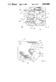
- FIG. 1 is a front perspective view of a typical Volkswagen type air-cooled engine (and a partially exploded view of an adapter of the prior art);
- FIG. 2 is an enlarged front elevation view showing the interior of a typical oil pump
- FIG. 3 is a front perspective view of a typical Volkswagen type engine having the oil pump cover of the present invention installed thereon;
- FIG. 4 is a front perspective view showing the oil pump cover of the present invention adjacent to the oil pump;
- FIG. 5 is an enlarged front perspective view of the oil pump cover installed on the oil pump with respective passage shown in dashed lines;
- FIG. 6 is a rear elevational view showing the inner surface of the oil pump cover with the respective passages shown in dashed lines;
- FIG. 7 is a front elevational view of the pump cover
- FIG. 8 is a top plan view of the pump cover and
- FIG. 9 is a left side elevational view of the pump cover.
- a typical early Volkswagen type air-cooled engine 10 is shown having a standard oil cooler 12 installed on the lower rear of the engine and located within an air cooling fan shroud 14.
- the engine has an oil pump located at the lower front and enclosed under a flat plate standard pump cover 16.
- one prior art method of adapting the standard engine to a full flow auxiliary oil system involved removal of the engine, then drilling a hole in the engine block into a high pressure oil passage, then tapping threads and installing a hosing fitting, such as at 18; and also drilling, tapping and installing a similar hose fitting, such as at 20 for an oil return inlet.
- an auxiliary oil filter or cooler was remotely attached to the vehicle and connected to the engine by suitable hoses at the fittings 18 and 20. This procedure is time consuming and requires the services of a skilled mechanic and results in a substantial expense to the owner.
- a typical oil pump 24 is illustrated particularly in FIGS. 2 and 4.
- the oil pump 24 comprises a cast aluminum generally cylindrical housing 26 enclosing a pair of rotatable pump gears 28, 30, has a suction chamber 32, a discharge chamber 34 and a front flange 35.
- the oil pump is installed within a recess in the lower front of the engine at about the level of the engine oil supply and is enclosed at the front flange by a standard flat plate oil pump cover 16 secured by four nuts on four studs extending from the engine.
- the suction chamber 32 includes a passage 36 which communicates with the engine oil supply to provide oil to the suction chamber.
- the upper pump gear 28 has a rear shaft lug engaged with the engine cam shaft (not shown) to drive the pump by rotating this gear 28 in a counter-clockwise rotation; and the engagement of the teeth of drive gear 28 with the teeth of gear 30 rotates gear 30 in a clockwise rotation.
- the oil in the suction chamber 32 is carried by the chambers between each tooth of gears 28 and 30 around the internal housing to the discharge chamber 34.
- the discharge chamber 34 includes a passage 38 which communicates with the engine oil circulation network in which oil is forced to the crank shaft bearings, push rods, valve lifters, etc. to lubricate the engine.
- the present invention provides a unique oil pump cover 40 which replaces the standard flat plate oil cover 16 on the engine.
- the pump cover 40 comprises a generally flat inner-surface 42 which seals the front of the pump on the engine, a unique baffle 44 which extends generally perpendicularly from the inner surface and is sized for segregating the discharge chamber 34, an outlet recess 46, an outlet passage 48, a return inlet passage 50, and an inlet recess 52.
- the baffle 44 Upon installation of the pump cover 40, the baffle 44 extends into the full longitudinal depth of the discharge chamber 34 of the oil pump, and spans the base of the chamber opening, essentially segregating the discharge chamber 34 into two discreet, (substantially sealed) compartments, illustrated in FIG. 4 as first compartment 34a and second compartment 34b, wherein Compartment 34b includes the discharge passage 38.
- the inner surface 42 of the pump cover includes the discharge outlet recess 46 which corresponds in shape to the shape of compartment 34a (defined by baffle 44 and the base of the gear teeth on gears 28 and 30 within the compartment.
- the outlet recess 46 smoothly increases in depth to communicate with the outlet passage 48 which extends to the exterior surface at the end of the cover.
- the outlet passage 48 includes internal threads adapted to receive a suitable fitting for connection of a suitable hose which is further connected to the inlet of an auxiliary oil cooler or oil filter or both in series.
- the return of the oil from the auxiliary cooler or filter back to the engine is provided by a suitable hose to the oil return inlet passage 50 having threads and a suitable fitting and located at the end of the pump cover.
- the return oil flows through the inlet passage 50 to the inlet recess 52 then out of the cover and further to the second compartment 34b of the discharge chamber to complete the auxiliary circuit then continues on through discharge passage 38 to the standard lubrication network system.
- the inlet recess 52 communicates with in inlet passage 50 and is separated from the outlet recess 46 by the baffle 44 and a partition 54 formed in the cover.
- the inlet recess 52 is illustrated in the figures as having a generally cylindrical shape.
- the initial production of the present pump covers were fabricated from an aluminum casting in which the outlet recess 46 was formed directly in the casting.
- the outlet passage 48 was first machined into the end of the cover in communication with the outlet recess 46.
- the inner-surface was then roughly machined (perpendicularly bored) for the return inlet recess, into which a cylindrical length of tubing (about two inches in length) was pressed (about 0.75 inches) into the casting and sealed therein forming the inlet recess 52 and partition 54, and the extended tube was further machined to form the baffle 44 extending perpendicularly from the inner-surface of the cover.
- the return inlet passage 50 was then machined into the end of the cover to include penetration of the tubing to communicate the inlet passage 50 with the inlet recess 52. It is contemplated that the cover will eventually be fabricated entirely from a one-piece casting and the return inlet recess 52 will be preferably in a generally triangular shape corresponding to the shape of chamber 34b. The cover will function as described regardless of the shape of the passages and recesses but the smoother the flow, the better the performance through the system.
- the pump cover could be fabricated or molded from any suitable aluminum, steel, ceramic, plastic or composite material.
- the exterior front surface of the cover is generally contoured to conform with the shape of the passages and preferably includes fins to facilitate cooling.
- the baffle 44 was previously described as extending perpendicularly from the inner-surface 42 of the cover and when the cover is installed, the baffle spans the longitudinal base of the opening of chamber 34.
- the concave-convex shape (formed naturally by the arc of the inserted tubing) performs well with the convex surface matching with the fit of the gears in compartment 34a, and the concave surface defining compartment 34b which smoothly directs oil to the passage 38; however, the baffle could be flat, and generally planer in shape.
- baffle 44 As an alternative means for segregating discharge chamber 34 into compartments 34a and 34b, a separate baffle (not specifically shown but similar in shape to baffle 44, only not integral with the pump cover) could be provided to be inserted and secured directly into the chamber 34 of the oil pump.
- the corresponding alternative cover would then include outlet recess 46 and inlet return recess 52 corresponding respectively to the compartments 34a and 34b of the discharge chamber but would not have the integral baffle 44.
- This two-piece design would simplify the casting and fabrication of the cover but would complicate the overall installation.
- This configuration could also be provided directly into an (after market) oil pump housing.
- the pump cover could be designed to segregate the suction chamber 32 into an inlet compartment and an outlet compartment.
- Such a configuration would require a slightly larger baffle corresponding to the span of the suction chamber but would otherwise include an inlet recess and inlet passage and an outlet recess and outlet passage similarly in structure but opposite to flow to that described in the foregoing preferred embodiment.
- This configuration would operate on the low pressure or suction side of the pump rather than the high pressure side as previously described.
- an auxiliary oil cooler or filter were to be mounted at a lower remote location, for example on the undercarriage of the vehicle. It is believed that this configuration would not perform as efficiently as in the dischrge chamber but would still fall within the scope of the present invention.
Abstract
Description
Claims (18)
Priority Applications (1)
| Application Number | Priority Date | Filing Date | Title |
|---|---|---|---|
| US07/174,823 US4834040A (en) | 1988-03-29 | 1988-03-29 | Oil pump cover which adapts a Volkswagen engine to a full flow auxiliary oil system |
Applications Claiming Priority (1)
| Application Number | Priority Date | Filing Date | Title |
|---|---|---|---|
| US07/174,823 US4834040A (en) | 1988-03-29 | 1988-03-29 | Oil pump cover which adapts a Volkswagen engine to a full flow auxiliary oil system |
Publications (1)
| Publication Number | Publication Date |
|---|---|
| US4834040A true US4834040A (en) | 1989-05-30 |
Family
ID=22637672
Family Applications (1)
| Application Number | Title | Priority Date | Filing Date |
|---|---|---|---|
| US07/174,823 Expired - Fee Related US4834040A (en) | 1988-03-29 | 1988-03-29 | Oil pump cover which adapts a Volkswagen engine to a full flow auxiliary oil system |
Country Status (1)
| Country | Link |
|---|---|
| US (1) | US4834040A (en) |
Cited By (8)
| Publication number | Priority date | Publication date | Assignee | Title |
|---|---|---|---|---|
| US5771854A (en) * | 1997-01-07 | 1998-06-30 | Ray Barton Racing Engines, Inc. | Oil pump adaptor |
| US5879140A (en) * | 1997-02-24 | 1999-03-09 | Ellison; Thomas W. | Oil pump pickup device for use with an internal combustion engine |
| US20040107940A1 (en) * | 2002-12-05 | 2004-06-10 | Elliott Christopher M. | Integrated gear train oil pump |
| US7174998B2 (en) * | 2001-10-15 | 2007-02-13 | Borgwarner Inc. | Submerged electric fluid pump |
| US20070207043A1 (en) * | 2006-03-03 | 2007-09-06 | Eastway Fair Company Limited Of Trident Chambers | Enclosed vertically mounted engine |
| US20070207042A1 (en) * | 2006-03-03 | 2007-09-06 | Hahn Klaus K | Engine shroud |
| US20130263827A1 (en) * | 2012-04-09 | 2013-10-10 | Frank A. Hughes | Oil pump modification system |
| US10161500B2 (en) * | 2015-03-31 | 2018-12-25 | Amarillo Gear Company Llc | Oil pump plate for in-line filter system |
Citations (3)
| Publication number | Priority date | Publication date | Assignee | Title |
|---|---|---|---|---|
| US4370957A (en) * | 1980-01-24 | 1983-02-01 | Hans List | Assembly of auxiliary equipment for a water-cooled internal combustion engine |
| US4423708A (en) * | 1981-12-31 | 1984-01-03 | Cummins Engine Company, Inc. | Liquid cooling unit for an internal combustion engine |
| US4424778A (en) * | 1982-09-30 | 1984-01-10 | Minoru Yoshida | Coupler for use in an oil cooling system |
-
1988
- 1988-03-29 US US07/174,823 patent/US4834040A/en not_active Expired - Fee Related
Patent Citations (3)
| Publication number | Priority date | Publication date | Assignee | Title |
|---|---|---|---|---|
| US4370957A (en) * | 1980-01-24 | 1983-02-01 | Hans List | Assembly of auxiliary equipment for a water-cooled internal combustion engine |
| US4423708A (en) * | 1981-12-31 | 1984-01-03 | Cummins Engine Company, Inc. | Liquid cooling unit for an internal combustion engine |
| US4424778A (en) * | 1982-09-30 | 1984-01-10 | Minoru Yoshida | Coupler for use in an oil cooling system |
Non-Patent Citations (2)
| Title |
|---|
| J. C. Whitney & Co., Parts & Accessories 1976, p. 124. * |
| J. C. Whitney & Co., Parts & Accessories, 1984 p. 270. * |
Cited By (10)
| Publication number | Priority date | Publication date | Assignee | Title |
|---|---|---|---|---|
| US5771854A (en) * | 1997-01-07 | 1998-06-30 | Ray Barton Racing Engines, Inc. | Oil pump adaptor |
| US5879140A (en) * | 1997-02-24 | 1999-03-09 | Ellison; Thomas W. | Oil pump pickup device for use with an internal combustion engine |
| US7174998B2 (en) * | 2001-10-15 | 2007-02-13 | Borgwarner Inc. | Submerged electric fluid pump |
| US20040107940A1 (en) * | 2002-12-05 | 2004-06-10 | Elliott Christopher M. | Integrated gear train oil pump |
| US6814044B2 (en) * | 2002-12-05 | 2004-11-09 | Caterpillar Inc | Integrated gear train oil pump |
| US20070207043A1 (en) * | 2006-03-03 | 2007-09-06 | Eastway Fair Company Limited Of Trident Chambers | Enclosed vertically mounted engine |
| US20070207042A1 (en) * | 2006-03-03 | 2007-09-06 | Hahn Klaus K | Engine shroud |
| US20130263827A1 (en) * | 2012-04-09 | 2013-10-10 | Frank A. Hughes | Oil pump modification system |
| US8807111B2 (en) * | 2012-04-09 | 2014-08-19 | Frank A. Hughes | Oil pump modification system |
| US10161500B2 (en) * | 2015-03-31 | 2018-12-25 | Amarillo Gear Company Llc | Oil pump plate for in-line filter system |
Similar Documents
| Publication | Publication Date | Title |
|---|---|---|
| US6267094B1 (en) | Oil pump module with filter in particular for internal combustion engine lubricating oil | |
| US6679692B1 (en) | Oil pump | |
| US7219645B2 (en) | Oil pump for a motorcycle | |
| US5921213A (en) | Adapter system for engine flushing apparatus | |
| US4834040A (en) | Oil pump cover which adapts a Volkswagen engine to a full flow auxiliary oil system | |
| KR20000047595A (en) | Structural oil pan with integrated oil filtration and cooling system | |
| US5771854A (en) | Oil pump adaptor | |
| SE522700C2 (en) | Internal combustion engine | |
| US7617811B2 (en) | Crankcase with adapter flange | |
| US3961614A (en) | Lubricating system for internal combustion engines | |
| US20080056887A1 (en) | Hydraulic gear motor with integrated filter | |
| US5879140A (en) | Oil pump pickup device for use with an internal combustion engine | |
| CA2153737A1 (en) | Rebuildable spin-on filters | |
| JP2003097346A (en) | Method for manufacturing cylinder head and crank case, and assembling method thereof | |
| CN200978718Y (en) | Flywheel casing gear chamber integral structure | |
| US4915852A (en) | Oil filter assembly for a Volkswagen flat four opposed cylinder air cooled engine | |
| EP0933511A2 (en) | Drive pulley for improved service of engine mounted accessories | |
| US6974315B2 (en) | Reduced friction gerotor | |
| US5785149A (en) | Screw-type compressor | |
| JPH0711955A (en) | Engine oil cooling device for water-cooled four-cycle engine | |
| JP2002180974A (en) | Oil pump for internal combustion engine | |
| CN111594338B (en) | Constant temperature crankcase with lubricating oil filters effect | |
| US3057434A (en) | Gear pump and sump for engine lubrication system | |
| JPH0144889B2 (en) | ||
| JPH0559925A (en) | Lubricating device of internal combustion engine |
Legal Events
| Date | Code | Title | Description |
|---|---|---|---|
| AS | Assignment |
Owner name: TURNER, ROGER, C., 702 SHALIMAR DRIVE, COSTA MESA, Free format text: ASSIGNMENT OF A PART OF ASSIGNORS INTEREST;ASSIGNOR:YOSHIDA, MINURO B.;REEL/FRAME:004893/0365 Effective date: 19880317 Owner name: KIMURO, HARUO, 6242 WARNER AVE, HUNTINGTON BEACH, Free format text: ASSIGNMENT OF A PART OF ASSIGNORS INTEREST;ASSIGNOR:YOSHIDA, MINURO B.;REEL/FRAME:004893/0368 Effective date: 19880317 Owner name: TURNER, ROGER C., CALIFORNIA Free format text: ASSIGNMENT OF A PART OF ASSIGNORS INTEREST;ASSIGNOR:YOSHIDA, MINURO B.;REEL/FRAME:004893/0365 Effective date: 19880317 Owner name: KIMURO, HARUO, CALIFORNIA Free format text: ASSIGNMENT OF A PART OF ASSIGNORS INTEREST;ASSIGNOR:YOSHIDA, MINURO B.;REEL/FRAME:004893/0368 Effective date: 19880317 |
|
| REMI | Maintenance fee reminder mailed | ||
| LAPS | Lapse for failure to pay maintenance fees | ||
| FP | Lapsed due to failure to pay maintenance fee |
Effective date: 19930530 |
|
| STCH | Information on status: patent discontinuation |
Free format text: PATENT EXPIRED DUE TO NONPAYMENT OF MAINTENANCE FEES UNDER 37 CFR 1.362 |