US4833791A - Step layout device - Google Patents
Step layout device Download PDFInfo
- Publication number
- US4833791A US4833791A US07/149,380 US14938088A US4833791A US 4833791 A US4833791 A US 4833791A US 14938088 A US14938088 A US 14938088A US 4833791 A US4833791 A US 4833791A
- Authority
- US
- United States
- Prior art keywords
- members
- pair
- pairs
- cooperating
- riser
- Prior art date
- Legal status (The legal status is an assumption and is not a legal conclusion. Google has not performed a legal analysis and makes no representation as to the accuracy of the status listed.)
- Expired - Fee Related
Links
- 230000036544 posture Effects 0.000 claims abstract description 6
- 230000000007 visual effect Effects 0.000 claims abstract description 4
- 230000007246 mechanism Effects 0.000 abstract description 3
- 238000010276 construction Methods 0.000 description 5
- 239000002184 metal Substances 0.000 description 3
- 238000000034 method Methods 0.000 description 3
- 230000000712 assembly Effects 0.000 description 2
- 238000000429 assembly Methods 0.000 description 2
- 230000000694 effects Effects 0.000 description 1
- 238000004049 embossing Methods 0.000 description 1
- 238000005530 etching Methods 0.000 description 1
- 238000009434 installation Methods 0.000 description 1
- 230000002452 interceptive effect Effects 0.000 description 1
- 239000000463 material Substances 0.000 description 1
- 238000005259 measurement Methods 0.000 description 1
- 238000012986 modification Methods 0.000 description 1
- 230000004048 modification Effects 0.000 description 1
- 238000007639 printing Methods 0.000 description 1
- 230000000284 resting effect Effects 0.000 description 1
- 239000011435 rock Substances 0.000 description 1
- 239000011343 solid material Substances 0.000 description 1
- 239000002023 wood Substances 0.000 description 1
Images

Classifications
-
- B—PERFORMING OPERATIONS; TRANSPORTING
- B43—WRITING OR DRAWING IMPLEMENTS; BUREAU ACCESSORIES
- B43L—ARTICLES FOR WRITING OR DRAWING UPON; WRITING OR DRAWING AIDS; ACCESSORIES FOR WRITING OR DRAWING
- B43L13/00—Drawing instruments, or writing or drawing appliances or accessories not otherwise provided for
- B43L13/20—Curve rulers or templets
- B43L13/201—Stencils for drawing figures, objects
- B43L13/206—Stencils for drawing figures, objects material objects
Definitions
- This invention concerns devices of the type designed to assist in the dimensioning and layout of complicated patterns, particularly stairways, wherein if an error, even minor, in measurement is once made, the end result can be calamitous, such as, e.g., the well known deep first step at the top of the stairs.
- the present invention has as its principal object therefore, to provide a layout device, especially one having the angular feature of a square, which can be used to give both a visual and physical representation of the relative dimensions and physical relationship of riser and tread, such that the builder can use the physical representation as a template or square to actually mark the stair carriage or casing sides for proper positioning of the risers and treads, and/or to visually check the installation of risers and treads as construction of the stairway proceeds.
- a step layout device for giving a visual and physical representation of riser and tread dimensions which have been or are being selected for a stairway, said device comprising at least one lower and one upper pair of planar members, the members of each pair having cooperating vertical ruler means and cooperating adjustable connector means adapted to planarly connect the members of each pair in selected vertically dimensioned riser postures, said pairs having adjacent horizontal edge portions provided with cooperating horizontal ruler means, and cooperating adjustable connector means on said pairs adapted to planarly connect said pairs in selected horizontally dimensioned tread postures.
- each said vertical ruler means comprises integer and fractional markings on at least one of the coincident edge portions of the pair members
- the said horizontal ruler means comprises integer and fractional markings on the horizontal edge portion of an adjacent member of the pairs;
- each of the members has a substantially rectangular configuration.
- FIG. 1 is a front view of the present device
- FIG. 2 is a cross-sectional view taken along line 2--2 of FIG. 1 in the direction of the arrows;
- FIG. 3 is a view as in FIG. 2 showing a variation in construction of the horizontal sliding joint
- FIG. 4 is a view as in FIG. 3 showing planar effect obtained by the use of thin sheet metal.
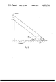
- FIG. 5 is a side view of a stair carriage as employed for layout calculations.
- the present layout device or square comprises at least two pairs exemplified by 10 and 12 of vertically adjustable members 14 and 16, and 18 and 20 respectively. These members preferably have a rectangular configuration such that their edges may be conveniently used for scribing or marking purposes as in pencilling the actual stair riser and tread outline on the stair carriage side supports.
- each pair is provided with a vertical adjustment means which, in the exemplary embodiment shown, comprises slots 22 and 24 in members 14 and 20 respectively which slidably receive wing nut type assemblies 26 and 28 respectively.
- the length of the slots dictate the extent of the vertical adjustment between the member of each pair, however, the slots may be placed in both members of each pair in order to maximize the adjustment and minimize the slot lengths which would afford greater structural integrity of the members.
- pair 12 has a minimum height in the closed position of four and one half inches, which with the addition of a one and one half inch tread would be satisfactory as a minimum riser height for the vast majority of situations.
- the minimum height in the closed position of pair 10 is shown as five inches, however a preferable height would be the treadthickness (e.g. 1.5 inches) more than the 4.5 inches of pair 12, i.e., six inches, such that employing the device with both pairs closed would give a consistent and quick first and second step height template of six inches. It is noted that errors in stair lay-out often occur at the first and second steps since it is easy not to take into account that the floor is in fact, a first thread.
- the maximum riser height for each pair as shown would be adequate for all conventional stairs. Should a greater range of riser heights be desired for special applications, then the dimensions of the members can be altered, and/or multiple members can be used, e.g., three or four members for each pair provided with suitable slot and fastening, non-interfering mechanisms.
- tread width adjustment is provided by means of slot 30 in member 18 and wing nut assemblies 32 mounted in a depending segment 33 of member 16. If desired, segment 33 and the slot 35 in which it slides may be extended, e.g., the full lengths of members 16 and 18 to give increased lateral support to the members and enhance their alignment.
- the embodiment shown provides for tread width adjustments betwen one and eighteen inches which again, is entirely adequate for any conventional stairway.
- the ruler markings along the edges of the members may, of course, be in any convention e.g., inches or metric and in any division thereof, and may comprise tape affixed to the members, or permanent markings thereon formed by printing, etching, embossing or the like.
- the material of construction is essentially at the option of the manufacturer and can be clear plastic sheeting of a thickness for example, of from about 1/16 to about 3/8 inches, however, metal, wood or any other solid material also may be used.
- Metal sheet as shown in FIG. 14 has the advantage of providing a more flat planar unit which would be easier to use as a template.
- the present device is used depends upon the particular construction technique used by the builder. For example, where a typical sheet rock wall defines one or both sides of the stairway, the device is simply placed with its bottom edge 34 resting on the floor and the members 14, 16, 18 and 20 as flat as possible against the wall. The outlines of the riser and treads represented by edges 36 and 38, and 40 and 42 respectively, are then readily marked on the wall. The exact initial positioning of the device on the floor, and dimensions of the risers and treads, of course, would have been previously determined by calculation techniques known in the art. Similarly, the outline can be traced progressively upwardly for positioning all of the stair risers. The present device can also be used to lay out the stairway outline on the stairway carriage or sideboards prior to the carriage being placed in position. The calculation techniques for such an operation again are well known in the art.
- tread width e.g., 111/4" from Table II, columns F and I;
- Tables I and II are exemplary in nature, illustrating a convenient reference for quickly determining possible stair dimensions, and are not intended to limit the utility of the present device.
- more than two pairs such as 10 and 12 may be employed, and theoretically, twenty or thirty or so pairs may be provided to afford a complete template for any size stairway, still utilizing the basic concepts of the present invention as embodied in the two pairs shown.
Landscapes
- Steps, Ramps, And Handrails (AREA)
Abstract
A step layout device for giving a visual and physical representation of riser and tread dimensions which have been or are being selected for a stairway, wherein the device has at least one lower and one upper pair of planar members, the members of each pair having cooperating vertical ruled portions and cooperating adjustable connector mechanisms adapted to planarly connect the members of each pair in selected vertically dimensioned riser postures, the pairs having adjacent horizontal edge portions provided with cooperating horizontal ruled portions, and cooperating adjustable connector mechanisms on the pairs adapted to planarly connect the pairs in selected horizontally dimensioned tread postures.
Description
This invention concerns devices of the type designed to assist in the dimensioning and layout of complicated patterns, particularly stairways, wherein if an error, even minor, in measurement is once made, the end result can be calamitous, such as, e.g., the well known deep first step at the top of the stairs.
The present invention has as its principal object therefore, to provide a layout device, especially one having the angular feature of a square, which can be used to give both a visual and physical representation of the relative dimensions and physical relationship of riser and tread, such that the builder can use the physical representation as a template or square to actually mark the stair carriage or casing sides for proper positioning of the risers and treads, and/or to visually check the installation of risers and treads as construction of the stairway proceeds.
This and other objects hereinafter appearing have been attained in accordance with the present invention through the discovery of the construction for a step layout device for giving a visual and physical representation of riser and tread dimensions which have been or are being selected for a stairway, said device comprising at least one lower and one upper pair of planar members, the members of each pair having cooperating vertical ruler means and cooperating adjustable connector means adapted to planarly connect the members of each pair in selected vertically dimensioned riser postures, said pairs having adjacent horizontal edge portions provided with cooperating horizontal ruler means, and cooperating adjustable connector means on said pairs adapted to planarly connect said pairs in selected horizontally dimensioned tread postures.
In preferred embodiments of the present invention:
each said vertical ruler means comprises integer and fractional markings on at least one of the coincident edge portions of the pair members;
the said horizontal ruler means comprises integer and fractional markings on the horizontal edge portion of an adjacent member of the pairs; and
each of the members has a substantially rectangular configuration.
The invention will be further understood from the following description and drawings wherein:
FIG. 1 is a front view of the present device;
FIG. 2 is a cross-sectional view taken along line 2--2 of FIG. 1 in the direction of the arrows; and
FIG. 3 is a view as in FIG. 2 showing a variation in construction of the horizontal sliding joint;
FIG. 4 is a view as in FIG. 3 showing planar effect obtained by the use of thin sheet metal; and
FIG. 5 is a side view of a stair carriage as employed for layout calculations.
Referring to the drawing, the present layout device or square comprises at least two pairs exemplified by 10 and 12 of vertically adjustable members 14 and 16, and 18 and 20 respectively. These members preferably have a rectangular configuration such that their edges may be conveniently used for scribing or marking purposes as in pencilling the actual stair riser and tread outline on the stair carriage side supports. As aforesaid, each pair is provided with a vertical adjustment means which, in the exemplary embodiment shown, comprises slots 22 and 24 in members 14 and 20 respectively which slidably receive wing nut type assemblies 26 and 28 respectively. The length of the slots dictate the extent of the vertical adjustment between the member of each pair, however, the slots may be placed in both members of each pair in order to maximize the adjustment and minimize the slot lengths which would afford greater structural integrity of the members.
In the embodiment shown, pair 12 has a minimum height in the closed position of four and one half inches, which with the addition of a one and one half inch tread would be satisfactory as a minimum riser height for the vast majority of situations. The minimum height in the closed position of pair 10 is shown as five inches, however a preferable height would be the treadthickness (e.g. 1.5 inches) more than the 4.5 inches of pair 12, i.e., six inches, such that employing the device with both pairs closed would give a consistent and quick first and second step height template of six inches. It is noted that errors in stair lay-out often occur at the first and second steps since it is easy not to take into account that the floor is in fact, a first thread. The maximum riser height for each pair as shown would be adequate for all conventional stairs. Should a greater range of riser heights be desired for special applications, then the dimensions of the members can be altered, and/or multiple members can be used, e.g., three or four members for each pair provided with suitable slot and fastening, non-interfering mechanisms.
The horizontal or tread width adjustment is provided by means of slot 30 in member 18 and wing nut assemblies 32 mounted in a depending segment 33 of member 16. If desired, segment 33 and the slot 35 in which it slides may be extended, e.g., the full lengths of members 16 and 18 to give increased lateral support to the members and enhance their alignment. The embodiment shown provides for tread width adjustments betwen one and eighteen inches which again, is entirely adequate for any conventional stairway.
The ruler markings along the edges of the members may, of course, be in any convention e.g., inches or metric and in any division thereof, and may comprise tape affixed to the members, or permanent markings thereon formed by printing, etching, embossing or the like. The material of construction is essentially at the option of the manufacturer and can be clear plastic sheeting of a thickness for example, of from about 1/16 to about 3/8 inches, however, metal, wood or any other solid material also may be used. Metal sheet as shown in FIG. 14 has the advantage of providing a more flat planar unit which would be easier to use as a template.
The manner in which the present device is used depends upon the particular construction technique used by the builder. For example, where a typical sheet rock wall defines one or both sides of the stairway, the device is simply placed with its bottom edge 34 resting on the floor and the members 14, 16, 18 and 20 as flat as possible against the wall. The outlines of the riser and treads represented by edges 36 and 38, and 40 and 42 respectively, are then readily marked on the wall. The exact initial positioning of the device on the floor, and dimensions of the risers and treads, of course, would have been previously determined by calculation techniques known in the art. Similarly, the outline can be traced progressively upwardly for positioning all of the stair risers. The present device can also be used to lay out the stairway outline on the stairway carriage or sideboards prior to the carriage being placed in position. The calculation techniques for such an operation again are well known in the art.
With reference to FIG. 5, an examplary determination of the settings for the present device for building a stairway between two floors of a house is given below in steps 1-5 wherein the numerical values have been taken from precalculated tables I and II wherein dimensions are in inches:
1. determine floor to floor height of, e.g., 120";
2. select desired riser height from table I, e.g., 6-21/32" from column D;
3. determine number of risers needed, e.g., 18 from column D' of Table I;
4. select tread width, e.g., 111/4" from Table II, columns F and I;
5. determine carriage length (x-y) by multiplying the number of risers (18) by the carriage factor 13.0716 from Table II, column J, the result of which is 235.29".
With reference to FIG. 5, the carriage factor (CF) is precalculated from riser heights "b" and tread widths "a" according to the equation CF=√a2 +b2.
It is noted that Tables I and II are exemplary in nature, illustrating a convenient reference for quickly determining possible stair dimensions, and are not intended to limit the utility of the present device.
                                  TABLE I
__________________________________________________________________________
FLOOR TO  RISER HEIGHT SETTING
                              NUMBER OF RISERS
FLOOR HEIGHT
          A   B   C   D   E   A' B' C' D' E'
__________________________________________________________________________
 94       7 27/32
              7 7/32
                  6 23/32
                      6 9/32  12 13 14 15
 95       7 29/32
              7 5/16
                  6 25/32
                      6 11/32 12 13 14 15
 96       8   73/8
                  6 27/32
                      6 13/32
                          6   12 13 14 15 16
 97       8 3/32
              7 15/32
                  6 15/16
                      6 15/32
                          6 1/16
                              12 13 14 15 16
 98       8 5/32
              7 17/32
                  7   6 17/32
                          61/8
                              12 13 14 15 16
 99       81/4
              75/8
                  7 1/16
                      6 19/32
                          6 3/16
                              12 13 14 15 16
100       7 11/16
              7 5/32
                  6 21/32
                      61/4    13 14 15 16
101       7 25/32
              7 7/32
                  6 23/32
                      6 5/16  13 14 15 16
102       7 27/32
              7 9/32
                  6 13/16
                      63/8    13 14 15 16
103       7 15/16
              7 11/32
                  67/8
                      6 7/16  13 14 15 16
104       8   7 7/16
                  6 15/16
                      61/2    13 14 15 16
105       8 1/16
              71/2
                  7   6 9/16
                          6 3/16
                              13 14 15 16 17
106       8 5/32
              7 9/16
                  7 1/16
                      65/8
                          61/4
                              13 14 15 16 17
107       8 7/32
              7 21/32
                  71/8
                      6 11/16
                          6 9/32
                              13 14 16 16 17
108       7 23/32
              7 3/16
                  63/4
                      6 11/32 14 15 16 17
109       7 25/32
              7 9/32
                  6 13/16
                      6 13/32 14 15 16 17
110       7 27/32
              7 11/32
                  67/8
                      6 15/32 14 15 16 17
111       7 15/16
              7 13/32
                  6 15/16
                      6 17/32 14 15 16 17
112       8   7 15/32
                  7   6 19/32 14 15 16 17
113       8 1/16
              7 17/32
                  7 1/16
                      6 21/32 14 15 16 17
114       8 5/32
              7 19/32
                  71/8
                      6 23/32 14 15 16 17
115       8 7/32
              7 21/32
                  7 3/16
                      63/4    14 15 16 17
116       7 23/32
              71/4
                  6 13/16
                      6 7/16  15 16 17 18
117       7 3/16
              7 5/16
                  67/8
                      61/2    15 16 17 18
118       7 7/8
              73/8
                  6 15/16
                      6 9/16  15 16 17 18
119       7 15/16
              7 7/16
                  7   65/8    15 16 17 18
120       8   71/2
                  7 1/16
                      6 21/32 15 16 17 18
121       8 1/16
              7 9/16
                  71/8
                      6 23/32 15 16 17 18
122       81/8
              75/8
                  7 3/16
                      6 25/32 15 16 17 18
123       7 11/16
              71/4
                  6 27/32     16 17 18
124       73/4
              7 9/32
                  67/8        16 17 18
125       7 13/16
              7 11/32
                  6 15/16     16 17 18
__________________________________________________________________________
                                  TABLE II
__________________________________________________________________________
         G         H       I         J
F        MINIMUM   CARRIAGE
                           MAXIMUM   CARRIAGE
RISER HEIGHT
         TREAD WIDTH
                   FACTOR (CF)
                           TREAD WIDTH
                                     FACTOR (CF)
__________________________________________________________________________
6        12        13.4164 121/2     13.8654
6 1/32   11 31/32  13.4024 12 13/32  13.7942
6 1/16   11 29/32  13.3608 12 11/32  13.7521
6 3/32   11 27/32  13.3194 12 9/32   13.7099
61/8     11 25/32  13.2783 12 7/32   13.6679
6 5/32   11 23/32  13.2373 12 5/32   13.6262
6 3/16   11 21/32  13.1967 12 3/32   13.5846
6 7/32   11 19/32  13.1562 12 1/32   13.5450
61/4     11 9/16   13.1435 12        13.5300
6 9/32   11 15/32  13.0761 11 15/16  13.4891
6 5/16   11 7/16   13.0638 117/8     13.4485
6 11/32  113/8     13.0243 11 13/16  13.4081
63/8     11 5/16   12.9851 113/4     13.3679
6 13/32  111/4     12.9461 11 11/16  13.3280
6 7/16   11 3/16   12.9074 115/8     13.2884
6 15/32  11 5/32   12.8959 11 19/32  13.2762
61/2     11 3/32   12.8577 11 17/32  13.2370
6 17/32  11 1/32   12.8197 11 15/32  13.1980
6 9/16   11        12.8088 11 13/32  13.1593
6 19/32  10 15/16  12.7713 113/8     13.1479
65/8     107/8     12.7340 11 5/16   13.1096
6 21/32  10 27/32  12.7236 111/4     13.0716
6 11/16  10 25/32  12.6868 11 3/16   13.0339
6 23/32  10 23/32  12.6503 11 5/32   13.0231
63/4     10 11/16  12.6406 11 3/32   12.9896
6 25/32  105/8     12.6046 11 1/32   12.9488
6 13/16  10 19/32  12.5951 11        12.9387
6 27/32  10 17/32  12.5595 10 15/16  12.9021
67/8     101/2     12.5505 10 29/32  12.8923
6 29/32  10 7/16   12.5154 10 27/32  12.8561
6 15/16  10 13/32  12.5067 10 25/32  12.8204
6 31/32  10 11/32  12.4722 103/4     12.8111
7        10 5/16   12.4638 10 11/16  12.7758
7 1/32   101/4     12.4298 10 21/32  12.7668
7 1/16   10 7/32   12.4218 10 19/32  12.7321
7 3/32   10 5/32   12.3883 10 9/16   12.7235
__________________________________________________________________________
As aforesaid, more than two pairs such as 10 and 12 may be employed, and theoretically, twenty or thirty or so pairs may be provided to afford a complete template for any size stairway, still utilizing the basic concepts of the present invention as embodied in the two pairs shown.
The invention has been described in detail with particular reference to preferred embodiments thereof, but it will be understood that variations and modifications will be effected within the spirit and scope of the invention.
Claims (4)
1. A step layout device for giving a visual and physical representation of riser and tread dimensions which have been or are being selected for a stairway, said device comprising at least one lower and one upper pair of planar rectangular members, the members of each pair having the same lengths and forming a rectangle, cooperating vertical ruler means on each of the members of each pair, and cooperating, vertically adjustable connector means on the members of each pair adapted to planarly connect the members of each pair in selected vertically dimensioned riser postures wherein the members of each pair form an adjusted rectangle, said pairs having adjacent horizontal edge portions provided with cooperating horizontal ruler means, and cooperating adjustable connector means on said pairs adapted to planarly connect said pairs in selected horizontally dimensioned tread postures.
2. The device of claim 1 wherein each said vertical ruler means comprises integar and fractional markings on at least one of the coincident edge portions of the pair members.
3. The device of claim 2 wherein the said horizontal ruler means comprises integer and fractional markings on the horizontal edge portion of an adjacent member of the pairs.
4. The device of claim 3 wherein each of the members has a substantially rectangular configuration.
Priority Applications (1)
| Application Number | Priority Date | Filing Date | Title |
|---|---|---|---|
| US07/149,380 US4833791A (en) | 1988-01-28 | 1988-01-28 | Step layout device |
Applications Claiming Priority (1)
| Application Number | Priority Date | Filing Date | Title |
|---|---|---|---|
| US07/149,380 US4833791A (en) | 1988-01-28 | 1988-01-28 | Step layout device |
Publications (1)
| Publication Number | Publication Date |
|---|---|
| US4833791A true US4833791A (en) | 1989-05-30 |
Family
ID=22530030
Family Applications (1)
| Application Number | Title | Priority Date | Filing Date |
|---|---|---|---|
| US07/149,380 Expired - Fee Related US4833791A (en) | 1988-01-28 | 1988-01-28 | Step layout device |
Country Status (1)
| Country | Link |
|---|---|
| US (1) | US4833791A (en) |
Cited By (6)
| Publication number | Priority date | Publication date | Assignee | Title |
|---|---|---|---|---|
| US20030177655A1 (en) * | 2000-08-23 | 2003-09-25 | Fordham Paul Ralph | Measuring device |
| US20060277779A1 (en) * | 2004-11-12 | 2006-12-14 | Alan Bauer | Mounting template |
| US7627955B1 (en) * | 2008-10-01 | 2009-12-08 | Thomas Raymond Perkey | Stringer guide template |
| US7954249B1 (en) * | 2010-04-09 | 2011-06-07 | E-Z Riser, Inc. | E-Z riser stair guide |
| US10723168B1 (en) * | 2017-01-25 | 2020-07-28 | Steven A. Mitchell | Stair layout template and method for using the template |
| US20210396017A1 (en) * | 2018-11-08 | 2021-12-23 | Dexx Ip Holdings, Llc | Modular staircase systems |
Citations (2)
| Publication number | Priority date | Publication date | Assignee | Title |
|---|---|---|---|---|
| DE15619C (en) * | J. J. WAMICH in Aachen, Ottostr. 81 | Innovations for web shooters | ||
| US164008A (en) * | 1875-06-01 | Improvement in stair-builders adjustable squares |
-
1988
- 1988-01-28 US US07/149,380 patent/US4833791A/en not_active Expired - Fee Related
Patent Citations (2)
| Publication number | Priority date | Publication date | Assignee | Title |
|---|---|---|---|---|
| DE15619C (en) * | J. J. WAMICH in Aachen, Ottostr. 81 | Innovations for web shooters | ||
| US164008A (en) * | 1875-06-01 | Improvement in stair-builders adjustable squares |
Cited By (8)
| Publication number | Priority date | Publication date | Assignee | Title |
|---|---|---|---|---|
| US20030177655A1 (en) * | 2000-08-23 | 2003-09-25 | Fordham Paul Ralph | Measuring device |
| US6826846B2 (en) * | 2000-08-23 | 2004-12-07 | Paul Ralph Fordham | Device for marking out a pattern on a surface |
| US20060277779A1 (en) * | 2004-11-12 | 2006-12-14 | Alan Bauer | Mounting template |
| US7627955B1 (en) * | 2008-10-01 | 2009-12-08 | Thomas Raymond Perkey | Stringer guide template |
| US7954249B1 (en) * | 2010-04-09 | 2011-06-07 | E-Z Riser, Inc. | E-Z riser stair guide |
| US10723168B1 (en) * | 2017-01-25 | 2020-07-28 | Steven A. Mitchell | Stair layout template and method for using the template |
| US20210396017A1 (en) * | 2018-11-08 | 2021-12-23 | Dexx Ip Holdings, Llc | Modular staircase systems |
| US11970865B2 (en) * | 2018-11-08 | 2024-04-30 | CB Interests Inc. | Modular staircase systems |
Similar Documents
| Publication | Publication Date | Title |
|---|---|---|
| US3842510A (en) | Electric outlet box locator | |
| US8122609B2 (en) | Step and rafter tool | |
| US5491905A (en) | Apparatus for accurately spacing railing spindles | |
| US5440818A (en) | Versatile measuring device | |
| US5692357A (en) | Adjustable template and jig | |
| US3328887A (en) | Layout tool | |
| CA1154587A (en) | Stud tape measure | |
| US6195904B1 (en) | Adjustable tile measuring device | |
| US5396710A (en) | Carpentry building tool and method of using same | |
| US2305124A (en) | Jig table for fabricating wall sections | |
| US4833791A (en) | Step layout device | |
| US5388340A (en) | Stair layout square with adjustable rake bar | |
| US6082019A (en) | Construction aid for determining length and angle of stair railings | |
| US3183598A (en) | Gauge for tile cutting | |
| CN102470528A (en) | Method and device for replicating contours | |
| US3907068A (en) | Ladder block | |
| US3478434A (en) | Stairs layout tools | |
| US4461196A (en) | Mitre box system for cutting compound angles | |
| US6775916B2 (en) | Framer's layout square | |
| US20250204704A1 (en) | Floor stand for clamping and putting up panel-shaped objects | |
| US2262827A (en) | Method of using jig tables | |
| US4059907A (en) | Electrical outlet and switchbox locator | |
| CN206397143U (en) | A kind of rapid construction stair template | |
| US4916796A (en) | Method for assembly of stair forms | |
| US20170009472A1 (en) | Method and apparatus for positioning, spacing and securement of studs within top and bottom framing plates |
Legal Events
| Date | Code | Title | Description |
|---|---|---|---|
| REMI | Maintenance fee reminder mailed | ||
| LAPS | Lapse for failure to pay maintenance fees | ||
| FP | Lapsed due to failure to pay maintenance fee |
Effective date: 19930530 |
|
| STCH | Information on status: patent discontinuation |
Free format text: PATENT EXPIRED DUE TO NONPAYMENT OF MAINTENANCE FEES UNDER 37 CFR 1.362 |