US4830696A - Method of manufacturing hollow furniture parts, such as table legs, as well as apparatus for carrying out said method - Google Patents
Method of manufacturing hollow furniture parts, such as table legs, as well as apparatus for carrying out said method Download PDFInfo
- Publication number
- US4830696A US4830696A US07/200,071 US20007188A US4830696A US 4830696 A US4830696 A US 4830696A US 20007188 A US20007188 A US 20007188A US 4830696 A US4830696 A US 4830696A
- Authority
- US
- United States
- Prior art keywords
- laminae
- wooden
- tube
- furniture parts
- prismatic
- Prior art date
- Legal status (The legal status is an assumption and is not a legal conclusion. Google has not performed a legal analysis and makes no representation as to the accuracy of the status listed.)
- Expired - Lifetime
Links
Images


Classifications
-
- B—PERFORMING OPERATIONS; TRANSPORTING
- B27—WORKING OR PRESERVING WOOD OR SIMILAR MATERIAL; NAILING OR STAPLING MACHINES IN GENERAL
- B27D—WORKING VENEER OR PLYWOOD
- B27D1/00—Joining wood veneer with any material; Forming articles thereby; Preparatory processing of surfaces to be joined, e.g. scoring
- B27D1/04—Joining wood veneer with any material; Forming articles thereby; Preparatory processing of surfaces to be joined, e.g. scoring to produce plywood or articles made therefrom; Plywood sheets
- B27D1/08—Manufacture of shaped articles; Presses specially designed therefor
- B27D1/086—Manufacture of oblong articles, e.g. tubes by spirally winding veneer blanks
-
- B—PERFORMING OPERATIONS; TRANSPORTING
- B27—WORKING OR PRESERVING WOOD OR SIMILAR MATERIAL; NAILING OR STAPLING MACHINES IN GENERAL
- B27M—WORKING OF WOOD NOT PROVIDED FOR IN SUBCLASSES B27B - B27L; MANUFACTURE OF SPECIFIC WOODEN ARTICLES
- B27M3/00—Manufacture or reconditioning of specific semi-finished or finished articles
- B27M3/0013—Manufacture or reconditioning of specific semi-finished or finished articles of composite or compound articles
- B27M3/0026—Manufacture or reconditioning of specific semi-finished or finished articles of composite or compound articles characterised by oblong elements connected laterally
- B27M3/0053—Manufacture or reconditioning of specific semi-finished or finished articles of composite or compound articles characterised by oblong elements connected laterally using glue
-
- B—PERFORMING OPERATIONS; TRANSPORTING
- B27—WORKING OR PRESERVING WOOD OR SIMILAR MATERIAL; NAILING OR STAPLING MACHINES IN GENERAL
- B27M—WORKING OF WOOD NOT PROVIDED FOR IN SUBCLASSES B27B - B27L; MANUFACTURE OF SPECIFIC WOODEN ARTICLES
- B27M3/00—Manufacture or reconditioning of specific semi-finished or finished articles
- B27M3/18—Manufacture or reconditioning of specific semi-finished or finished articles of furniture or of doors
-
- Y—GENERAL TAGGING OF NEW TECHNOLOGICAL DEVELOPMENTS; GENERAL TAGGING OF CROSS-SECTIONAL TECHNOLOGIES SPANNING OVER SEVERAL SECTIONS OF THE IPC; TECHNICAL SUBJECTS COVERED BY FORMER USPC CROSS-REFERENCE ART COLLECTIONS [XRACs] AND DIGESTS
- Y10—TECHNICAL SUBJECTS COVERED BY FORMER USPC
- Y10T—TECHNICAL SUBJECTS COVERED BY FORMER US CLASSIFICATION
- Y10T156/00—Adhesive bonding and miscellaneous chemical manufacture
- Y10T156/10—Methods of surface bonding and/or assembly therefor
- Y10T156/1052—Methods of surface bonding and/or assembly therefor with cutting, punching, tearing or severing
-
- Y—GENERAL TAGGING OF NEW TECHNOLOGICAL DEVELOPMENTS; GENERAL TAGGING OF CROSS-SECTIONAL TECHNOLOGIES SPANNING OVER SEVERAL SECTIONS OF THE IPC; TECHNICAL SUBJECTS COVERED BY FORMER USPC CROSS-REFERENCE ART COLLECTIONS [XRACs] AND DIGESTS
- Y10—TECHNICAL SUBJECTS COVERED BY FORMER USPC
- Y10T—TECHNICAL SUBJECTS COVERED BY FORMER US CLASSIFICATION
- Y10T156/00—Adhesive bonding and miscellaneous chemical manufacture
- Y10T156/17—Surface bonding means and/or assemblymeans with work feeding or handling means
- Y10T156/1702—For plural parts or plural areas of single part
- Y10T156/1712—Indefinite or running length work
- Y10T156/1715—Means joining indefinite length work edge to edge
-
- Y—GENERAL TAGGING OF NEW TECHNOLOGICAL DEVELOPMENTS; GENERAL TAGGING OF CROSS-SECTIONAL TECHNOLOGIES SPANNING OVER SEVERAL SECTIONS OF THE IPC; TECHNICAL SUBJECTS COVERED BY FORMER USPC CROSS-REFERENCE ART COLLECTIONS [XRACs] AND DIGESTS
- Y10—TECHNICAL SUBJECTS COVERED BY FORMER USPC
- Y10T—TECHNICAL SUBJECTS COVERED BY FORMER US CLASSIFICATION
- Y10T156/00—Adhesive bonding and miscellaneous chemical manufacture
- Y10T156/17—Surface bonding means and/or assemblymeans with work feeding or handling means
- Y10T156/1702—For plural parts or plural areas of single part
- Y10T156/1712—Indefinite or running length work
- Y10T156/1737—Discontinuous, spaced area, and/or patterned pressing
-
- Y—GENERAL TAGGING OF NEW TECHNOLOGICAL DEVELOPMENTS; GENERAL TAGGING OF CROSS-SECTIONAL TECHNOLOGIES SPANNING OVER SEVERAL SECTIONS OF THE IPC; TECHNICAL SUBJECTS COVERED BY FORMER USPC CROSS-REFERENCE ART COLLECTIONS [XRACs] AND DIGESTS
- Y10—TECHNICAL SUBJECTS COVERED BY FORMER USPC
- Y10T—TECHNICAL SUBJECTS COVERED BY FORMER US CLASSIFICATION
- Y10T156/00—Adhesive bonding and miscellaneous chemical manufacture
- Y10T156/17—Surface bonding means and/or assemblymeans with work feeding or handling means
- Y10T156/1702—For plural parts or plural areas of single part
- Y10T156/1712—Indefinite or running length work
- Y10T156/1741—Progressive continuous bonding press [e.g., roll couples]
Definitions
- the invention relates to a method of manufacturing hollow furniture parts, such as table legs, said method being optionally continuous, and comprising conveying wooden laminae to a work station to form the furniture parts.
- the object of the invention is to provide a method enabling the manufacture of furniture parts with prismatic shape in a simple manner while avoiding such steps in the process resulting in considerable inner stresses in the wood.
- the inventive method is characterized by the number of wooden laminae conveyed to a modeling unit provided with polygonally, preferably squarely arranged guide surfaces corresponding to the number of said guide surfaces, the wooden laminae sliding across the guide surfaces while abutting said surfaces, and the longitudinal edges of the individual lamina being undercut so that the laminae form a prismatic, hollow tube subsequent to being assembled, the side surfaces of said tube being mitred along the longitudinal edges of the tube, and the wooden laminae being glued together in pairs by means of a fast-drying glue applied shortly before the laminae reach the modeling unit, and support and/or end blocks being optionally inserted in and glued to the inside of the prismatic tube, whereupon said tube is cut into small pieces corresponding to the furniture parts.
- the laminae used are wooden veneers or fiberboards.
- the inventive end blocks used are provided with recesses for fastening the furniture part to other furniture parts, thus facilitating the attachment of said furniture part to another part of the furniture.
- the inventive support block is arranged in the middle of the inside of the furniture part, such as a table leg, giving the furniture part mechanical strength despite it being hollow and of comparatively light weight.
- the outside of the prismatic tube is sanded down along the mitred edges subsequent to the assembly of the wooden laminae but before the cutting into furniture parts, thus ensuring a finished, consumer-friendly surface of the furniture part.
- the inventive guide surfaces of the modeling unit are arranged such that they form the sides of a triangle, preferably an equilateral triangle, resulting in a triangular cross-section of the furniture part.
- a table leg of such a cross-section is especially suitable for a low coffee table.
- inventive support and/or end blocks have been fastened to one of the wooden laminae before it reaches the modeling unit.
- the manufacture of the prismatic tube and thus the furniture part is especially simple.
- long pieces of wooden lamina are used instead of an endless lamina, the length of said pieces corresponding to once, twice or several times the length of a furniture part, such as the length of a table leg.
- the invention also relates to an apparatus for carrying out the inventive method, said apparatus being characterized in that it comprises a number of holders for the wooden laminae to form a prismatic tube, a modeling unit having guide bodies provided with corresponding guide surfaces polygonally arranged along the sides of the modeling unit for assembling the wooden laminae and conveying the resulting prismatic tube, a number of glue application means for applying glue to the longitudinal edges of the wooden laminae, and optionally a sanding means, and a cutting means for cutting off furniture parts of a desired length from the prismatic tube.
- a number of holders for the wooden laminae to form a prismatic tube characterized in that it comprises a number of holders for the wooden laminae to form a prismatic tube, a modeling unit having guide bodies provided with corresponding guide surfaces polygonally arranged along the sides of the modeling unit for assembling the wooden laminae and conveying the resulting prismatic tube, a number of glue application means for applying glue to the longitudinal edges of the wooden laminae
- the guide bodies are arranged in such a way that their guide surfaces form a square aperture of a size corresponding to the cross-section of the furniture part, such as a table leg. This renders the apparatus especially suitable for the manufacture of all types of table legs.
- the guide bodies are slightly staggered with respect to each other seen in the forward direction of the prismatic tube, resulting in more space for the shafts of the guide bodies.
- inventive guide bodies are rigid and form an integral unit by constituting a large block with an aperture where the prismatic tube is formed. This is an especially suitable embodiment when the wooden laminae are to be conveyed at a low velocity.
- the guide surfaces are stationary, since there is no risk of extensive friction between the guide surfaces of the modeling unit and the wooden laminae.
- FIG. 1 is a diagrammatic, lateral view of an apparatus for carrying out the inventive method
- FIG. 2 illustrates an embodiment of the modeling unit of the apparatus, where the guide bodies with corresponding guide surfaces form substantially a square
- FIG. 3 is a perspective view of a table leg manufactured according to the inventive method, the parts of said table leg being separate,
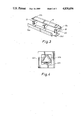
- FIG. 4 is a perspective view of a modeling unit, where the three guide bodies are arranged to form substantially an equilateral triangle,
- FIG. 5 illustrates a modeling unit in form of a solid block with an aperture, where the defining surfaces of the aperture form the guide surfaces for the wooden laminae,
- FIGS. 6 and 6A illustrate a table leg during its manufacture, where pieces of wooden lamina with a predetermined length are used instead of an endless lamina, and
- FIG. 7 is a cross-sectional view of a square table leg with mitred corners.
- the apparatus of FIG. 1 comprises a bottom plate 1 above which there is mounted a modeling unit 2 carrying a number of guide bodies with corresponding guide surfaces 2'.
- FIG. 2 illustrates how the guide bodies comprise the rollers 5a, 5b, 5c, 5d being of circular cross-section.
- the guide surfaces are the curved surfaces 2a', 2b', 2c', 2d' of the rollers 5a, 5b, 5c, 5d.
- the guide bodies are arranged such that they substantially form the sides of a square.
- the use of more guide bodies than four, i.e. a guide body for each side of a polygon is also possible.
- the guide bodies can be slightly staggered with respect to each other, seen in the longitudinal direction of the apparatus, so that the shafts of the rollers do not impede each other.
- the apparatus of FIG. 1 comprises furthermore four holders 6a, 6b, 6c, for rolls of bands of wooden lamina (actually fiberboard) (the fourth holder is hidden behind the holder 6c and thus not provided with a reference numeral).
- the rolls of wooden lamina have cores (not shown) with large diameters to ensure that the wooden laminae reeled off the rolls have a comparatively slight curvature when they are on the rolls.
- a cutting means 45 for cutting off finished furniture parts, such as table legs, from a prismatic tube 7 formed by wooden laminae 6a', 6b', 6c', 6d' at the modeling unit 2.
- the apparatus of FIG. 1 is furthermore provided with several glue application means 10 at the corners of the square formed by the guide bodies 5a, 5b, 5c, 5d.
- the apparatus is provided with n glue application nozzles each at a corner of the polygon, and with n guide bodies.
- FIG. 3 illustrates a table leg manufactured by means of the inventive method, the parts of said table leg being separate.
- end blocks 19 Inside the table leg a support block 19 is inserted, preferably in the middle of the leg.
- the end blocks are optionally provided with recesses 20 (depicted with a dotted line) to ensure an easy mounting of the table leg to a table leaf.
- the modeling unit can comprise only three guide surfaces 32a, 32b, 32c, cf. FIG. 4, in which there are only three rotating guide bodies. The latter are arranged such that they substantially form the sides of a triangle, preferably an equilateral triangle.
- the modeling unit can also comprise a solid plate 40 with an aperture 41 in its middle, said aperture being provided with a number of guide surfaces 12a, 12b, 12c, 12d.
- a modeling unit is used when the friction between the conveyed wooden laminae and the guide surfaces is negligible during conveyance.
- the inventive method is carried out on an inventive apparatus in the following way:
- the rolls of wooden lamina are placed in their respective holders 6a, 6b, 6c, 6d, whereupon the wooden laminae 6a', 6b', 6c', 6d' are pulled or pushed through the modeling unit 2, said wooden laminae abutting the guide surfaces 2a', 2b', 2c', 2d' of the guide bodies 5a, 5b, 5c, 5d, cf.
- FIG. 1 The individual wooden lamina is mitred along its longitudinal edges, i.e. it is undercut, so that it forms an even joint with its neighbouring laminae.
- the undercutting on a wooden lamina is performed either in advance or by conveying the wooden lamina through an undercutting means (not shown) of the apparatus, where the undercutting is performed by e.g. planing or sanding.
- glue is applied to the longitudinal edges of the wooden laminae from the application nozzles 10.
- the nozzles are supplied with glue by means of a common tubing system (not shown).
- the glue is preferably of the fast-drying type.
- the wooden laminae are glued together to form a prismatic tube 7, cf.
- the prismatic tube can be provided with support and/or end blocks 18, 19, cf. FIGS. 2 and 3.
- the blocks are in advance attached to the wooden lamina 2d' on the side facing the inside of the prismatic tube 7.
- the blocks are usually of such a cross-section that they fill out the entire cross-section of the prismatic tube 7.
- Subsequent to the wooden laminae having passed the modeling unit and the glue having dried the prismatic tube is cut into small pieces corresponding to the individual furniture parts, typically table legs. The cutting is performed by the cutting means 45.
- the wooden laminae used are e.g. wooden veneer or fiberboard.
- a sanding means 25 diagrammatically shown in FIG. 1. The sanding occurs after the wooden laminae have been assembled but before the cutting into suitable parts.
- the prismatic tube 7 has the cross-section of an equilateral triangle instead of a square
- the wooden laminae pass through the modeling unit of FIG. 4.
- the longitudinal edges of each lamina are in this case undercut by 30°.
- the longitudinal edges of the wooden laminae of FIG. 2 are undercut by 45°.
- pieces of wooden lamina can be used for the inventive method.
- Such pieces can have a length corresponding to twice or several times the length of the furniture part, such as a table leg.
- the individual piece of wooden lamina 30b is conveyed to the modeling unit 2 by means of a holding means 32 operating with vacuum, the outer ends of said holding means being provided with suction cups 33 ensuring a secure hold of the piece of wooden lamina 30b.
- wooden lamina refers to lamina band made of wood.
- the term is, however, to be understood in a much broader sense, since it covers many other materials, such as plastics or press-wood.
Landscapes
- Engineering & Computer Science (AREA)
- Life Sciences & Earth Sciences (AREA)
- Manufacturing & Machinery (AREA)
- Wood Science & Technology (AREA)
- Forests & Forestry (AREA)
- Mechanical Engineering (AREA)
- Tables And Desks Characterized By Structural Shape (AREA)
- Connection Of Plates (AREA)
- Electrical Discharge Machining, Electrochemical Machining, And Combined Machining (AREA)
- Passenger Equipment (AREA)
- Laminated Bodies (AREA)
Abstract
A method of manufacturing hollow furniture parts, such as table legs comprises conveying wooden laminae to a work station to form the furniture parts. The number of wooden laminae conveyed to a modeling unit provided with polygonally, preferably squarely arranged guide surfaces corresponds to the number of said guide surfaces. The wooden laminae slide across the guide surfaces while abutting said surfaces. The longitudinal edges of the individual lamina are undercut so that the laminae form a prismatic, hollow tube subsequent to being assembled. The side surfaces of said tube are mitred along the longitudinal edges of the tube, and the wooden laminae are glued together in pairs by means of a fast-drying glue applied shortly before the laminae reach the modeling unit. Support and/or end blocks are then optionally inserted in and glued to the inside of the prismatic tube. Finally the tube is cut into small pieces corresponding to the furniture parts. This method enables the manufacture of furniture parts with prismatic shape in a simple manner while avoiding such steps in the process resulting in considerable inner stresses in the wood.
Description
The invention relates to a method of manufacturing hollow furniture parts, such as table legs, said method being optionally continuous, and comprising conveying wooden laminae to a work station to form the furniture parts.
It has been known for a long time to manufacture tubes of wooden veneer with circular cross-section by helically wrapping strips of veneer. This method is, however, unsuitable for the manufacture of a large number of pieces of furniture, where the furniture parts are to be prismatic or possibly rectangular. Moreover, there is a risk of considerable stresses to be developed in the wood due to the strong bending the wood is subjected to.
The object of the invention is to provide a method enabling the manufacture of furniture parts with prismatic shape in a simple manner while avoiding such steps in the process resulting in considerable inner stresses in the wood.
The inventive method is characterized by the number of wooden laminae conveyed to a modeling unit provided with polygonally, preferably squarely arranged guide surfaces corresponding to the number of said guide surfaces, the wooden laminae sliding across the guide surfaces while abutting said surfaces, and the longitudinal edges of the individual lamina being undercut so that the laminae form a prismatic, hollow tube subsequent to being assembled, the side surfaces of said tube being mitred along the longitudinal edges of the tube, and the wooden laminae being glued together in pairs by means of a fast-drying glue applied shortly before the laminae reach the modeling unit, and support and/or end blocks being optionally inserted in and glued to the inside of the prismatic tube, whereupon said tube is cut into small pieces corresponding to the furniture parts. This results in a simple method of manufacturing the desired prismatic furniture parts without running the risk of serious inner stresses in the wood, as the wooden laminae are conveyed to the modeling unit substantially without being deformed. At the modeling unit the wooden laminae are glued together in pairs at the undercut longitudinal edges so that a prismatic tube is formed. The glue is of the fast-drying type to ensure that the tube does not collapse right after the modeling unit. The support and/or end blocks are inserted to reinforce the prismatic tube. Finally the prismatic tube is cut into small pieces corresponding to the furniture parts. The end blocks close the openings at the end of the furniture parts so that the hollowness of the furniture parts is not noticed.
In an especially suitable embodiment of the invention the laminae used are wooden veneers or fiberboards.
The inventive end blocks used are provided with recesses for fastening the furniture part to other furniture parts, thus facilitating the attachment of said furniture part to another part of the furniture.
The inventive support block is arranged in the middle of the inside of the furniture part, such as a table leg, giving the furniture part mechanical strength despite it being hollow and of comparatively light weight.
According to the invention the outside of the prismatic tube is sanded down along the mitred edges subsequent to the assembly of the wooden laminae but before the cutting into furniture parts, thus ensuring a finished, consumer-friendly surface of the furniture part.
The inventive guide surfaces of the modeling unit are arranged such that they form the sides of a triangle, preferably an equilateral triangle, resulting in a triangular cross-section of the furniture part. A table leg of such a cross-section is especially suitable for a low coffee table.
Furthermore, the inventive support and/or end blocks have been fastened to one of the wooden laminae before it reaches the modeling unit. As a result the manufacture of the prismatic tube and thus the furniture part is especially simple.
According to the invention long pieces of wooden lamina are used instead of an endless lamina, the length of said pieces corresponding to once, twice or several times the length of a furniture part, such as the length of a table leg. As a result the risk of undesired stresses in the prismatic tube is very low, as it is almost unnecessary to bend the wooden laminae during their way to the modeling unit.
The invention also relates to an apparatus for carrying out the inventive method, said apparatus being characterized in that it comprises a number of holders for the wooden laminae to form a prismatic tube, a modeling unit having guide bodies provided with corresponding guide surfaces polygonally arranged along the sides of the modeling unit for assembling the wooden laminae and conveying the resulting prismatic tube, a number of glue application means for applying glue to the longitudinal edges of the wooden laminae, and optionally a sanding means, and a cutting means for cutting off furniture parts of a desired length from the prismatic tube. This ensures an especially simple and inexpensive manufacture of the inventive furniture part.
In one embodiment of the inventive apparatus the guide bodies are arranged in such a way that their guide surfaces form a square aperture of a size corresponding to the cross-section of the furniture part, such as a table leg. This renders the apparatus especially suitable for the manufacture of all types of table legs.
According to the invention the guide bodies are slightly staggered with respect to each other seen in the forward direction of the prismatic tube, resulting in more space for the shafts of the guide bodies.
Finally, the inventive guide bodies are rigid and form an integral unit by constituting a large block with an aperture where the prismatic tube is formed. This is an especially suitable embodiment when the wooden laminae are to be conveyed at a low velocity. The guide surfaces are stationary, since there is no risk of extensive friction between the guide surfaces of the modeling unit and the wooden laminae.
The invention is described in greater detail below and with reference to the accompanying drawings, in which
FIG. 1 is a diagrammatic, lateral view of an apparatus for carrying out the inventive method,
FIG. 2 illustrates an embodiment of the modeling unit of the apparatus, where the guide bodies with corresponding guide surfaces form substantially a square,
FIG. 3 is a perspective view of a table leg manufactured according to the inventive method, the parts of said table leg being separate,
FIG. 4 is a perspective view of a modeling unit, where the three guide bodies are arranged to form substantially an equilateral triangle,
FIG. 5 illustrates a modeling unit in form of a solid block with an aperture, where the defining surfaces of the aperture form the guide surfaces for the wooden laminae,
FIGS. 6 and 6A illustrate a table leg during its manufacture, where pieces of wooden lamina with a predetermined length are used instead of an endless lamina, and
FIG. 7 is a cross-sectional view of a square table leg with mitred corners.
The apparatus of FIG. 1 comprises a bottom plate 1 above which there is mounted a modeling unit 2 carrying a number of guide bodies with corresponding guide surfaces 2'. FIG. 2 illustrates how the guide bodies comprise the rollers 5a, 5b, 5c, 5d being of circular cross-section. In this case the guide surfaces are the curved surfaces 2a', 2b', 2c', 2d' of the rollers 5a, 5b, 5c, 5d. In FIG. 2 the guide bodies are arranged such that they substantially form the sides of a square. On the other hand, the use of more guide bodies than four, i.e. a guide body for each side of a polygon, is also possible. The guide bodies can be slightly staggered with respect to each other, seen in the longitudinal direction of the apparatus, so that the shafts of the rollers do not impede each other.
The apparatus of FIG. 1 comprises furthermore four holders 6a, 6b, 6c, for rolls of bands of wooden lamina (actually fiberboard) (the fourth holder is hidden behind the holder 6c and thus not provided with a reference numeral). The rolls of wooden lamina have cores (not shown) with large diameters to ensure that the wooden laminae reeled off the rolls have a comparatively slight curvature when they are on the rolls. Instead of said rolls of wooden lamina long pieces of wooden lamina (bands) of a predetermined length, see below, can also be used. On the right-hand side of FIG. 1 the apparatus is provided with a cutting means 45 for cutting off finished furniture parts, such as table legs, from a prismatic tube 7 formed by wooden laminae 6a', 6b', 6c', 6d' at the modeling unit 2.
The apparatus of FIG. 1 is furthermore provided with several glue application means 10 at the corners of the square formed by the guide bodies 5a, 5b, 5c, 5d. When the guide bodies form an n-sided polygon instead of a rectangle, the apparatus is provided with n glue application nozzles each at a corner of the polygon, and with n guide bodies.
FIG. 3 illustrates a table leg manufactured by means of the inventive method, the parts of said table leg being separate. There are four pieces of wooden lamina 16a, 16b, 16c, 16d, each of their ends being provided with end blocks 18. Inside the table leg a support block 19 is inserted, preferably in the middle of the leg. The end blocks are optionally provided with recesses 20 (depicted with a dotted line) to ensure an easy mounting of the table leg to a table leaf.
Instead of a modeling unit with four guide surfaces (one on each rotating guide body) the modeling unit can comprise only three guide surfaces 32a, 32b, 32c, cf. FIG. 4, in which there are only three rotating guide bodies. The latter are arranged such that they substantially form the sides of a triangle, preferably an equilateral triangle.
The modeling unit can also comprise a solid plate 40 with an aperture 41 in its middle, said aperture being provided with a number of guide surfaces 12a, 12b, 12c, 12d. Such a modeling unit is used when the friction between the conveyed wooden laminae and the guide surfaces is negligible during conveyance.
The inventive method is carried out on an inventive apparatus in the following way:
The rolls of wooden lamina are placed in their respective holders 6a, 6b, 6c, 6d, whereupon the wooden laminae 6a', 6b', 6c', 6d' are pulled or pushed through the modeling unit 2, said wooden laminae abutting the guide surfaces 2a', 2b', 2c', 2d' of the guide bodies 5a, 5b, 5c, 5d, cf. FIG. 1. The individual wooden lamina is mitred along its longitudinal edges, i.e. it is undercut, so that it forms an even joint with its neighbouring laminae. The undercutting on a wooden lamina is performed either in advance or by conveying the wooden lamina through an undercutting means (not shown) of the apparatus, where the undercutting is performed by e.g. planing or sanding. Simultaneous with the laminae 6a', 6b', 6c', 6d' being conveyed through the modeling unit (and abutting the guide surfaces) glue is applied to the longitudinal edges of the wooden laminae from the application nozzles 10. The nozzles are supplied with glue by means of a common tubing system (not shown). The glue is preferably of the fast-drying type. Subsequent to passing the modeling unit 2 the wooden laminae are glued together to form a prismatic tube 7, cf. FIG. 7. The prismatic tube can be provided with support and/or end blocks 18, 19, cf. FIGS. 2 and 3. The blocks are in advance attached to the wooden lamina 2d' on the side facing the inside of the prismatic tube 7. The blocks are usually of such a cross-section that they fill out the entire cross-section of the prismatic tube 7. Subsequent to the wooden laminae having passed the modeling unit and the glue having dried the prismatic tube is cut into small pieces corresponding to the individual furniture parts, typically table legs. The cutting is performed by the cutting means 45.
The wooden laminae used are e.g. wooden veneer or fiberboard. Optionally the outside of the prismatic tube 7 is sanded down along the mitred edges by a sanding means 25, diagrammatically shown in FIG. 1. The sanding occurs after the wooden laminae have been assembled but before the cutting into suitable parts.
If it is desired that the prismatic tube 7 has the cross-section of an equilateral triangle instead of a square, the wooden laminae pass through the modeling unit of FIG. 4. The longitudinal edges of each lamina are in this case undercut by 30°. The longitudinal edges of the wooden laminae of FIG. 2 are undercut by 45°.
When the wooden laminae are very smooth the modeling unit 2 of FIG. 5 is most suitable.
Instead of an endless lamina (rolled-up wooden lamina) comparatively long pieces of wooden lamina can be used for the inventive method. Such pieces can have a length corresponding to twice or several times the length of the furniture part, such as a table leg. In this case the individual piece of wooden lamina 30b is conveyed to the modeling unit 2 by means of a holding means 32 operating with vacuum, the outer ends of said holding means being provided with suction cups 33 ensuring a secure hold of the piece of wooden lamina 30b.
In the present application the term "wooden lamina" refers to lamina band made of wood. The term is, however, to be understood in a much broader sense, since it covers many other materials, such as plastics or press-wood.
The invention may be varied in many ways without thus deviating from the scope of the invention.
Claims (12)
1. A method of manufacturing hollow furniture parts, such as table legs, said method being optionally continuous, and comprising conveying wooden laminae to a work station to form the furniture parts, wherein the number of wooden laminae (6a', 6b', 6c', 6d') conveyed to a modeling unit provided with polygonally, preferably squarely arranged guide surfaces corresponds to the number of said guide surfaces, the wooden laminae sliding across the guide surfaces while abutting said surfaces, and the longitudinal edges of the individual lamina being undercut so that the laminae form a prismatic, hollow tube (7) subsequent to being assembled, the side surfaces of said tube being mitred along the longitudinal edges of the tube, and the wooden laminae (6a'-6d') being glued together in pairs by means of a fast-drying glue applied shortly before the laminae reach the modeling unit (2), and support and/or end blocks (18, 19) being optionally inserted in and glued to the inside of the prismatic tube (7), whereupon said tube is cut into small pieces corresponding to the furniture parts (16).
2. A method as in claim 1, wherein the laminae (6a', 6b', 6c', 6d') used are wooden veneers or fiberboards.
3. A method as in claim 1, wherein the end blocks (18) used are provided with recesses (20) for fastening the furniture part to other furniture parts.
4. A method as in claim 1, wherein the support block (19) is arranged in the middle of the inside of the furniture part, such as a table leg.
5. A method as in claim 1, wherein subsequent to the assembly of the wooden laminae (6a', 6b', 6c', 6d') but before the cutting into furniture parts the outside of the prismatic tube (7) is sanded down (at 25) along the mitred edges.
6. A method as in claim 1, wherein the guide surfaces (32a, 32b, 32c) of the modeling unit (2) are arranged such that they form the sides of a triangle, preferably an equilateral triangle.
7. A method as in 1, wherein the support and/or end blocks (18, 19) have been previously fastened to one of the wooden laminae (6d').
8. A method as in claim 1, wherein long pieces of wooden lamina are used instead of an endless lamina, the length of said pieces corresponding to once, twice or several times the length of a furniture part, such as the length of a table leg.
9. An apparatus for carrying out the method according to claim 1, wherein said apparatus comprises a number of holders (6a, 6b, 6c, 6d) for the wooden laminae (6a', 6b', 6c', 6d') to form a prismatic tube (7), a modeling unit (2) having guide bodies (5a, 5b, 5c, 5d) provided with corresponding guide surfaces (2a', 2b', 2c', 2d') polygonally arranged along the sides of the modeling unit (2) for assembling the wooden laminae and conveying the resulting prismatic tube (7), a number of glue application means (10) for applying glue to the longitudinal edges of the wooden laminae (6a', 6b', 6c', 6d'), and optionally a sanding means (25) and a cutting means (45) for cutting off furniture parts of a desired length from the prismatic tube (7).
10. An apparatus as in claim 9, wherein the guide bodies (5a, 5b, 5c, 5d) are arranged in such a way that their guide surfaces (2a', 2b', 2c', 2d') form a square aperture of a size corresponding to the cross-section of the furniture part, such as a table leg.
11. An apparatus as in claim 9, wherein the guide bodies (5a, 5b, 5c, 5d) are slightly staggered with respect to each other seen in the forward direction of the prismatic tube (7).
12. An apparatus as in claim 9, wherein the guide bodies (5a, 5b, 5c, 5d) are rigid and form an integral unit by constituting a large block (40) with an aperture (41) where the prismatic tube (7) is formed.
Applications Claiming Priority (2)
| Application Number | Priority Date | Filing Date | Title |
|---|---|---|---|
| DK272987A DK154930C (en) | 1987-05-27 | 1987-05-27 | PROCEDURE FOR MANUFACTURING HOLE FURNITURE, LIKE THE TABLE, AND APPARATUS FOR EXERCISING THE PROCEDURE |
| DK2729/87 | 1987-05-27 |
Publications (1)
| Publication Number | Publication Date |
|---|---|
| US4830696A true US4830696A (en) | 1989-05-16 |
Family
ID=8115145
Family Applications (1)
| Application Number | Title | Priority Date | Filing Date |
|---|---|---|---|
| US07/200,071 Expired - Lifetime US4830696A (en) | 1987-05-27 | 1988-05-27 | Method of manufacturing hollow furniture parts, such as table legs, as well as apparatus for carrying out said method |
Country Status (6)
| Country | Link |
|---|---|
| US (1) | US4830696A (en) |
| EP (1) | EP0292961B1 (en) |
| AT (1) | ATE104584T1 (en) |
| DE (1) | DE3889146T2 (en) |
| DK (1) | DK154930C (en) |
| NO (1) | NO166768C (en) |
Cited By (2)
| Publication number | Priority date | Publication date | Assignee | Title |
|---|---|---|---|---|
| CN103692533A (en) * | 2013-12-13 | 2014-04-02 | 惠州市新金马家具制造有限公司 | 3D (three dimensional) piano baking varnish manufacturing process for furniture |
| RU227740U1 (en) * | 2024-06-05 | 2024-07-31 | Евгения Владимировна Большакова | Furniture support |
Families Citing this family (3)
| Publication number | Priority date | Publication date | Assignee | Title |
|---|---|---|---|---|
| FI82744C (en) * | 1988-07-26 | 1991-04-10 | Jouko Vekkeli | TRAEKONSTRUKTION. |
| SE509600C2 (en) * | 1996-06-28 | 1999-02-15 | Lars Hammarstroem | Method, apparatus and use in bonding |
| DE102004001791B3 (en) * | 2004-01-12 | 2005-09-01 | Bernd Frick | Hollow body used in the manufacture of furniture legs comprises a triangular cross-section which changes size along the annular periphery and has a concave surface, a convex surface and a planar surface |
Citations (7)
| Publication number | Priority date | Publication date | Assignee | Title |
|---|---|---|---|---|
| US1314007A (en) * | 1919-08-26 | Ewinor mcgrueb | ||
| US2348291A (en) * | 1943-01-22 | 1944-05-09 | Plymold Corp | Manufacture of plywood tubing and the like |
| US2352533A (en) * | 1942-11-28 | 1944-06-27 | Plymold Corp | Manufacture of wood tubing and the like |
| US3269440A (en) * | 1965-03-15 | 1966-08-30 | William P Duncan | Method of fabricating wooden gutters |
| US3493021A (en) * | 1967-12-26 | 1970-02-03 | Harwood Dimensions Canada Ltd | Composite wooden articles made from grainwood sticks and method and machine for making them |
| GB2092948A (en) * | 1981-02-02 | 1982-08-25 | Department Of Timber Technolog | Veneer laminated wooden tubes |
| US4638843A (en) * | 1984-12-05 | 1987-01-27 | Raute Oy | Method for the manufacture of a veneer beam |
Family Cites Families (4)
| Publication number | Priority date | Publication date | Assignee | Title |
|---|---|---|---|---|
| US2631956A (en) * | 1948-06-01 | 1953-03-17 | Bostadsforskning Ab | Method and device for the manufacture of box girders |
| DE881570C (en) * | 1951-08-07 | 1953-07-02 | Josef Heine | Table leg |
| US2956850A (en) * | 1957-10-29 | 1960-10-18 | Winthrop W G White | Table leg joint connection |
| US3477485A (en) * | 1967-05-19 | 1969-11-11 | Potlatch Forests Inc | Method for assembling wooden t and i beams |
-
1987
- 1987-05-27 DK DK272987A patent/DK154930C/en active
-
1988
- 1988-05-25 NO NO882298A patent/NO166768C/en not_active IP Right Cessation
- 1988-05-26 DE DE3889146T patent/DE3889146T2/en not_active Expired - Lifetime
- 1988-05-26 AT AT8888108413T patent/ATE104584T1/en not_active IP Right Cessation
- 1988-05-26 EP EP88108413A patent/EP0292961B1/en not_active Expired - Lifetime
- 1988-05-27 US US07/200,071 patent/US4830696A/en not_active Expired - Lifetime
Patent Citations (7)
| Publication number | Priority date | Publication date | Assignee | Title |
|---|---|---|---|---|
| US1314007A (en) * | 1919-08-26 | Ewinor mcgrueb | ||
| US2352533A (en) * | 1942-11-28 | 1944-06-27 | Plymold Corp | Manufacture of wood tubing and the like |
| US2348291A (en) * | 1943-01-22 | 1944-05-09 | Plymold Corp | Manufacture of plywood tubing and the like |
| US3269440A (en) * | 1965-03-15 | 1966-08-30 | William P Duncan | Method of fabricating wooden gutters |
| US3493021A (en) * | 1967-12-26 | 1970-02-03 | Harwood Dimensions Canada Ltd | Composite wooden articles made from grainwood sticks and method and machine for making them |
| GB2092948A (en) * | 1981-02-02 | 1982-08-25 | Department Of Timber Technolog | Veneer laminated wooden tubes |
| US4638843A (en) * | 1984-12-05 | 1987-01-27 | Raute Oy | Method for the manufacture of a veneer beam |
Cited By (3)
| Publication number | Priority date | Publication date | Assignee | Title |
|---|---|---|---|---|
| CN103692533A (en) * | 2013-12-13 | 2014-04-02 | 惠州市新金马家具制造有限公司 | 3D (three dimensional) piano baking varnish manufacturing process for furniture |
| CN103692533B (en) * | 2013-12-13 | 2016-04-06 | 惠州市新金马家具制造有限公司 | A kind of 3D piano baking vanish manufacture craft for furniture |
| RU227740U1 (en) * | 2024-06-05 | 2024-07-31 | Евгения Владимировна Большакова | Furniture support |
Also Published As
| Publication number | Publication date |
|---|---|
| DE3889146T2 (en) | 1994-09-08 |
| NO166768B (en) | 1991-05-27 |
| EP0292961A2 (en) | 1988-11-30 |
| DE3889146D1 (en) | 1994-05-26 |
| EP0292961A3 (en) | 1991-04-03 |
| NO166768C (en) | 1991-09-04 |
| DK154930B (en) | 1989-01-09 |
| DK272987A (en) | 1988-11-28 |
| EP0292961B1 (en) | 1994-04-20 |
| NO882298L (en) | 1988-11-28 |
| DK154930C (en) | 1989-05-29 |
| NO882298D0 (en) | 1988-05-25 |
| ATE104584T1 (en) | 1994-05-15 |
| DK272987D0 (en) | 1987-05-27 |
Similar Documents
| Publication | Publication Date | Title |
|---|---|---|
| US5576082A (en) | Wood tubing | |
| US4394409A (en) | Composite wood article and method of manufacture | |
| US4830696A (en) | Method of manufacturing hollow furniture parts, such as table legs, as well as apparatus for carrying out said method | |
| US2388541A (en) | Method of manufacturing laminated articles from veneer or like sheet material | |
| WO1998023422A1 (en) | A method for the manufacture of a curved wooden fibre plate and a wooden fibre plate manufactured hereby | |
| US4401496A (en) | Veneer salvage technique | |
| US4308963A (en) | Shelves | |
| EP0059026B1 (en) | Improvements in wood veneers | |
| EP0139529A2 (en) | Container | |
| DE3415053A1 (en) | Process and device for glueing edge bands onto profiled workpieces | |
| ES2907487T3 (en) | Manufacturing procedure of multilayer solid wood panels | |
| EP1532895A1 (en) | Method of continuously producing foldable panels | |
| CN210173822U (en) | Full-automatic edge bonding machine | |
| FI86908B (en) | FOERFARANDE OCH ANLAEGGNING FOER AUTOMATISK SAMMANFOGNING AV RAETVINKLIGA RAMKONSTRUKTIONER. | |
| DE59809853D1 (en) | Laminated wooden beams | |
| AU2001100611A4 (en) | A hollow acoustic substantially cylindrical drum | |
| US3695966A (en) | Method of manufacturing furniture fabrication cores | |
| EP0947298A1 (en) | A method for the manufacture of a furniture panel and a panel obtained by such a method | |
| GB2290051A (en) | Forming panel corners | |
| EP1532896B1 (en) | Method of continuously producing foldable panels | |
| GB2272858A (en) | Veneer manufacturing | |
| JPS59500126A (en) | Laminated wood manufacturing method and manufacturing device | |
| GB2063760A (en) | Shelves | |
| NL8002239A (en) | Decorative wall cladding system - uses chamfered strips with ends inserted in grooves in uprights | |
| DE9413041U1 (en) | Striped edge band |
Legal Events
| Date | Code | Title | Description |
|---|---|---|---|
| AS | Assignment |
Owner name: INTER-IKEA A/S, NY STRANDVEJ 21, DK-3050 HUMLEBAEK Free format text: ASSIGNMENT OF ASSIGNORS INTEREST.;ASSIGNOR:PETERSSON, OLLE;REEL/FRAME:004918/0781 Effective date: 19880510 |
|
| STCF | Information on status: patent grant |
Free format text: PATENTED CASE |
|
| FEPP | Fee payment procedure |
Free format text: PAYOR NUMBER ASSIGNED (ORIGINAL EVENT CODE: ASPN); ENTITY STATUS OF PATENT OWNER: LARGE ENTITY |
|
| FPAY | Fee payment |
Year of fee payment: 4 |
|
| FPAY | Fee payment |
Year of fee payment: 8 |
|
| FPAY | Fee payment |
Year of fee payment: 12 |