US4828218A - Multiple mode regulator - Google Patents
Multiple mode regulator Download PDFInfo
- Publication number
- US4828218A US4828218A US07/127,442 US12744287A US4828218A US 4828218 A US4828218 A US 4828218A US 12744287 A US12744287 A US 12744287A US 4828218 A US4828218 A US 4828218A
- Authority
- US
- United States
- Prior art keywords
- fluid
- region
- flow rate
- port
- diaphragm
- Prior art date
- Legal status (The legal status is an assumption and is not a legal conclusion. Google has not performed a legal analysis and makes no representation as to the accuracy of the status listed.)
- Expired - Lifetime
Links
Images


Classifications
-
- B—PERFORMING OPERATIONS; TRANSPORTING
- B05—SPRAYING OR ATOMISING IN GENERAL; APPLYING FLUENT MATERIALS TO SURFACES, IN GENERAL
- B05B—SPRAYING APPARATUS; ATOMISING APPARATUS; NOZZLES
- B05B12/00—Arrangements for controlling delivery; Arrangements for controlling the spray area
- B05B12/08—Arrangements for controlling delivery; Arrangements for controlling the spray area responsive to condition of liquid or other fluent material to be discharged, of ambient medium or of target ; responsive to condition of spray devices or of supply means, e.g. pipes, pumps or their drive means
- B05B12/085—Arrangements for controlling delivery; Arrangements for controlling the spray area responsive to condition of liquid or other fluent material to be discharged, of ambient medium or of target ; responsive to condition of spray devices or of supply means, e.g. pipes, pumps or their drive means responsive to flow or pressure of liquid or other fluent material to be discharged
- B05B12/087—Flow or presssure regulators, i.e. non-electric unitary devices comprising a sensing element, e.g. a piston or a membrane, and a controlling element, e.g. a valve
- B05B12/088—Flow or presssure regulators, i.e. non-electric unitary devices comprising a sensing element, e.g. a piston or a membrane, and a controlling element, e.g. a valve the sensing element being a flexible member, e.g. membrane, diaphragm, bellows
-
- B—PERFORMING OPERATIONS; TRANSPORTING
- B05—SPRAYING OR ATOMISING IN GENERAL; APPLYING FLUENT MATERIALS TO SURFACES, IN GENERAL
- B05B—SPRAYING APPARATUS; ATOMISING APPARATUS; NOZZLES
- B05B12/00—Arrangements for controlling delivery; Arrangements for controlling the spray area
- B05B12/08—Arrangements for controlling delivery; Arrangements for controlling the spray area responsive to condition of liquid or other fluent material to be discharged, of ambient medium or of target ; responsive to condition of spray devices or of supply means, e.g. pipes, pumps or their drive means
- B05B12/085—Arrangements for controlling delivery; Arrangements for controlling the spray area responsive to condition of liquid or other fluent material to be discharged, of ambient medium or of target ; responsive to condition of spray devices or of supply means, e.g. pipes, pumps or their drive means responsive to flow or pressure of liquid or other fluent material to be discharged
- B05B12/087—Flow or presssure regulators, i.e. non-electric unitary devices comprising a sensing element, e.g. a piston or a membrane, and a controlling element, e.g. a valve
-
- G—PHYSICS
- G05—CONTROLLING; REGULATING
- G05D—SYSTEMS FOR CONTROLLING OR REGULATING NON-ELECTRIC VARIABLES
- G05D7/00—Control of flow
- G05D7/03—Control of flow with auxiliary non-electric power
-
- Y—GENERAL TAGGING OF NEW TECHNOLOGICAL DEVELOPMENTS; GENERAL TAGGING OF CROSS-SECTIONAL TECHNOLOGIES SPANNING OVER SEVERAL SECTIONS OF THE IPC; TECHNICAL SUBJECTS COVERED BY FORMER USPC CROSS-REFERENCE ART COLLECTIONS [XRACs] AND DIGESTS
- Y10—TECHNICAL SUBJECTS COVERED BY FORMER USPC
- Y10T—TECHNICAL SUBJECTS COVERED BY FORMER US CLASSIFICATION
- Y10T137/00—Fluid handling
- Y10T137/7722—Line condition change responsive valves
- Y10T137/7781—With separate connected fluid reactor surface
- Y10T137/7793—With opening bias [e.g., pressure regulator]
- Y10T137/7797—Bias variable during operation
Definitions
- This invention relates to coating material delivery systems and particularly to a system characterized by flow rates variable over a wider range than was heretofore possible.
- Such widely variable flow rates permit rapid purging of, for example, one color or type of coating material from the coating material distribution circuit during a coating material changeover, while also permitting careful control of the much lower flow rates characteristic of dispensing coating materials.
- Some coating material dispensing systems are characterized by frequent changes in the type of coating material being dispensed.
- An example of such systems is an automotive coating application line on which essentially each car which is conveyed along the line is coated with a different color from the car immediately ahead of it on the line and the car immediately after it on the line.
- Each type, e.g., color, of coating material has its own characteristics, such as viscosity, and the dispensing system is set up so that one or more regulators in the coating material dispensing circuit for the system are supplied with desired coating material flow rate-related signals which insure that the various different coating materials are dispensed at the appropriate, usually constant, rates from an output terminal of the coating material dispensing circuit.
- a regulator for controlling the flow rate of a fluid material being dispensed through a coating material dispensing circuit comprises a regulator body defining a cavity, means defining a valve seat region in the cavity, means defining an entry port into the cavity on one side of the seat region, and means defining an exit port from the cavity on the other side of the seat region.
- a movable valve member includes a valve portion engageable with the valve seat region to close the cavity between the entry port and the exit port. The valve member is movable to a position at which the valve portion is out of engagement with the seat region to open a passageway between the entry port and the exit port.
- the regulator further includes a first diaphragm, means for mounting the first diaphragm movably in the regulator body to divide the cavity into a first region in fluid communication with the passageway and a second region not in fluid communication with the passageway, a second diaphragm, and means for mounting the second diaphragm movably in the regulator body to divide the second region into a third region and a fourth region.
- the third region lies adjacent the first region and on the opposite side of the first diaphragm therefrom and the fourth region lies adjacent the third region and on the opposite side of the second diaphragm therefrom.
- the regulator further includes means defining an entry port into the third region, means defining an entry port into the fourth region and means for coupling the first and second diaphragms to the movable valve member.
- the area of the first diaphragm exposed in the first and third regions is relatively greater than the area of the second diaphragm exposed in the third and fourth regions.
- the regulator further comprises a third diaphragm, means for mounting the third diaphragm movably in the regulator body in the third region, and means providing vent openings through the regulator body from the cavity to the exterior of the regulator body between the first and third diaphragms.
- a system for controlling the rate of flow of a fluid dispensed in a fluid coating material dispensing circuit includes sources of first and second fluids to be dispensed from the coating material dispensing circuit, means for providing a desired first fluid flow rate-related signal, means for providing a desired second fluid flow rate-related signal, a fluid utilization output, and a fluid flow rate regulator for alternatively controlling the flow rate of the first fluid at the fluid utilization output in response to the desired first fluid flow rate-related signal or the flow rate of the second fluid at the fluid utilization output in response to the desired second fluid flow rate-related signal.
- the regulator includes a first fluid flow rate-related signal input port and a second fluid flow rate-related signal input port, a selected fluid input port, a selected fluid output port, means for coupling the selected fluid input port alternatively to the source of the first fluid or the source of the second fluid, and means for coupling the selected fluid output port to the fluid utilization output.
- Means are provided for coupling the source of the first fluid flow rate-related signal to the first fluid flow rate-related signal input port, and for coupling the source of the second fluid flow rate-related signal to the second fluid flow rate-related signal input port.
- the means for providing the desired second fluid flow rate-related signal comprises a three-way valve having a pilot input port and first and second pilot-controlled ports.
- the signal at the pilot input port alternatively isolates the first pilot-controlled port and simultaneously vents the second pilot-controlled port or couples the first and second pilot-controlled ports.
- a pilot signal source is provided, as are means for coupling the pilot signal source to the pilot input port, means for coupling the means for providing the desired first fluid flow rate-related signal and the first fluid flow-rate related signal input port to the first pilot-controlled port, and means for coupling the second fluid flow rate-related signal input port to the second pilot-controlled port.
- the means for coupling the selected fluid input port to the source of the first fluid and to the source of the second fluid comprises a manifold, a first valve, and a second valve. Means are provided for coupling the source of the first fluid to the first valve, the first valve to the manifold, the source of the second fluid to the second valve, the second valve to the manifold, and the manifold to the selected fluid input port.
- the second fluid illustratively is a purgative for purging the first fluid from at least a portion of the fluid coating material dispensing circuit.
- the second fluid is a solvent for the first fluid.
- FIG. 1 illustrates two control curves which help explain both a problem with prior art coating material flow rate regulators and how the present invention solves that problem;
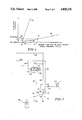
- FIG. 2 illustrates a sectional side elevational view of a regulator for controlling the flow rate of a fluid material being dispensed through a coating material dispensing circuit according to the present invention
- FIG. 3 illustrates a system for controlling the rate of flow of a selected one of a number of fluids to be dispensed through a fluid coating material dispensing circuit according to the present invention
- FIG. 4 illustrates another system for controlling the rate of flow of a selected one of a number of fluids to be dispensed through a fluid coating material dispensing circuit according to the present invention.
- FIG. 5 illustrates two control curves which help explain another use for the dual-mode regulator of the present invention.
- the straight line 20 is a plot of fluid delivery rate in cm 3 /min. versus the pilot signal pressure in p.s.i.g. to a conventional air piloted paint pressure regulator.
- Point 22 on curve 20 illustrates the pilot signal pressure of 5.2 p.s.i.g. (3.6 nt/cm 2 ) which must be provided to deliver 45 cm 3 /min. of a particular coating material through the regulator.
- point 24 on curve 20 illustrates the pilot signal pressure of 5.8 p.s.i.g. (4 nt/cm 2 ) which must be provided to deliver 55 cm 3 /min. of that same coating material through the regulator.
- the pilot signal pressure will have to be maintained carefully in a range only 0.6 p.s.i. 0.4 nt/cm 2 ) wide. This is frequently difficult to do.
- Curve 26 has a much lower slope than curve 20.
- point 28 on curve 26 corresponds to a flow rate of 45 cm 3 /min. and 11 p.s.i.g. (7.6 nt/cm 2 ) (rather than 5.2 p.s.i.g. 3.6 nt/cm 2 ).
- Point 30 on curve 26 corresponds to a flow rate of 55 cm 3 /min. and 16 p.s.i.g. (11 nt/cm 2 ) (rather than 5.8 p.s.i.g.--4 nt/cm 2 ).
- pilot signal range between 45 cm 3 /min. and 55 cm 3 /min has been improved from 0.6 p.s.i. (0.4 nt/cm 2 ) to 5 p.s.i. (3.4 nt/cm 2 ), which is a much easier tolerance to control.
- curve 26 were the only curve describing the operation of the regulator, very large pilot pressures would be required to drive large volumes of solvent through the coating material dispensing circuit to purge it in the short times provided between coating material dispensing cycles. Therefore, at least during the purging and cleaning cycle, it would be desirable to return to fluid delivery rate versus pilot signal pressure curve 20.
- the regulator 40 includes a body composed of an upper section 42, intermediate sections 43, 44, and a lower section 46.
- a cavity 48 is defined within the interiors 50, 52, 53, 54 of the upper section 42, intermediate sections 43, 44, and lower section 46, respectively. Sections through the cavity 48 transverse to the plane of FIG. 2 and extending across FIG. 2 from side to side are generally circular.
- a combination valve housing and coupler 56 is threaded into a threaded opening 58 at the lower end of lower section 46 and captures a valve seat-providing insert 60 against the underside 62 of lower section 46.
- Valve housing 56 captures a valve member 68 which includes a generally hemispherical upper portion 70 which cooperates with the valve seat 72 provided on insert 60.
- Valve member 68 also includes a central generally right circular cylindrical valve guiding portion 76 and a lower, downwardly projecting valve stem portion 78.
- a coiled compression spring 80 urges the valve member 68 upwardly and the upper portion 70 of valve member 68 into sealing engagement with valve seat 72.
- Valve actuator 94 is suspended from the center of a first diaphragm 98, the perimeter 100 of which is captured between lower section 46 and intermediate section 44 to divide the cavity 48 into a first region 102 below diaphragm 98 and a second region 104 above diaphragm 98.
- Second region 104 is divided by a second diaphragm 106 suspended by the capture of its perimeter 108 between intermediate section 43 and upper section 42 into third and fourth regions 110, 112, respectively.
- a pilot pressure signal inlet 114 is provided into fourth region 112.
- a pilot pressure signal inlet 116 is provided into third region 110.
- a fluid outlet 120 communicates with the first region.
- Second diaphragm 106 Downward movement of second diaphragm 106 is transmitted to valve actuator 94 through a valve actuator part 122 which extends upward above diaphragm 98 and contacts the underside of diaphragm 106 when the diaphragms 98, 106 are in their undeflected orientations.
- O-ring seals in grooves 124, 126 prevent seepage of fluid from valve housing 56 and around valve seat 72, respectively.
- An O-ring seal in a groove 128 prevents seepage of fluid from the first region 102 through a screw hole in first diaphragm 98 which accommodates a screw by which valve actuator part 122 is attached to valve actuator 94.
- the upper, intermediate, and lower sections are held together, and the perimeters 100, 108 of diaphragms 98, 106, respectively, held in place by cap screws 130.
- the intermediate section, or bleed ring, 44 provides the isolation, or stand-off, region 53 of cavity 48. Vents 129 are provided around the periphery of intermediate section 44.
- vents 129 vent region 53 of section 44 so that any fluid which leaks from first region 102 upward past valve actuator 94, the O-ring in groove 128 and first diaphragm 98 will leak from regulator 40 through vents 129.
- a diaphragm 131 and a spacer 133 are inserted between first diaphragm 98 and valve actuator part 122 and held in place, respectively, by cap screws 130 and the screw which joins parts 122, 94.
- Region 53, vents 129 and diaphragm 131 thus further protect inlets 114, 116 from the fluid in first region 102.
- a system incorporating regulator 40 controls the rates of flow of selected coating materials and purging materials, such as solvents, from a multiple color manifold 134, such as the manifold illustrated in U.S. Pat. No. 4,311,724, to an output terminal 136 of a coating material dispensing circuit 138 which supplies coating material to a dispensing device 140, such as the devices illustrated in U.S. Pat. No. 4,148,932.
- the selected material flows from manifold 134 through a line 135 to the inlet end 90 of regulator 40.
- the outlet 120 of regulator 40 is coupled through a line 137 to the output terminal 136 of circuit 138.
- An analog fluid pilot signal from a system such as the system described in U.S. Pat. No.
- 4,362,124 is coupled through a line 143 to pilot pressure signal inlet 114 of regulator 40 and to one inlet terminal 142 of a three-way valve 144.
- An outlet 145 of three-way valve 144 is coupled through a line 147 to pilot pressure signal inlet 116 of regulator 40.
- a dump pilot signal which may also be provided by a system such as that described in U.S. Pat. No. 4,362,124, is coupled through a line 149 to the control input 146 of three-way valve 144. Typically this dump pilot signal is also coupled through line 149 to the dispensing device 140.
- the fluid (typically compressed air) pilot signal is supplied to inlet 114.
- the pilot signal causes a relatively lesser total force to be exerted downward on diaphragm 106 and transmitted through valve actuator part 122, spacer 133, valve actuator 94 and needle 96 to valve member 68.
- pilot signal pressure versus flow rate curve 26 of FIG. 1 is duplicated.
- the dump pilot signal occurs at control input 146 of three-way valve 144, the analog fluid pilot signal is supplied not only to inlet 114 but also to inlet 116.
- pilot signal Owing to the relatively larger area of first diaphragm 98 exposed to third region 110, the pilot signal causes a relatively greater total force to be exerted downward on diaphragm 131 and transmitted through spacer 133, valve actuator 94 and needle 96 to valve member 68. Under these circumstances, pilot signal pressure versus flow rate curve 20 of FIG. 1 is duplicated.
- regulator 40 can be "stacked" into regulator 40.
- Each can be provided with its own pilot signal input and a multiple mode regulator having characteristics in addition to those illustrated in FIG. 1 can be realized. These additional characteristics can have slopes shallower than the slope of curve 26, or slopes between curves 20 and 26, or slopes steeper than the slope of curve 20, as dictated by the needs of a particular application.
- FIG. 4 another system incorporating regulator 40 controls the rates of flow of selected coating materials and purging materials, such as solvents, from a multiple color manifold 164, such as the manifold illustrated in U.S. Pat. No. 4,311,724, to an output terminal 166 of a coating material dispensing circuit 168 which supplies coating material to a dispensing device 170, such as the devices illustrated in U.S. Pat. No. 4,148,932.
- the selected material flows from manifold 164 through a line 165 to the inlet end 90 of regulator 40.
- the outlet 120 of regulator 40 is coupled through a line 167 to the output terminal 166 of circuit 168.
- a first analog fluid pilot signal from a system such as the system described in U.S. Pat. No.
- 4,362,124 is coupled through a line 173 to pilot pressure signal inlet 114 of regulator 40.
- a second analog fluid pilot signal from a system such as that described in U.S. Pat. No. 4,362,124 is coupled through a line 177 to pilot pressure signal inlet 116 of regulator 40.
- the two channels of control, lines 173, 177, are separately controllable through software written specifically for such an installation.
- the regulator 40 of the present invention is also useful in other situations.
- articles being conveyed serially past a coating material dispensing device are to be coated alternately with a first coating material having a lower viscosity or a second coating material having a higher viscosity.
- the same volume/minute, X cm 3 /min., of either the first or second coating material is to be dispensed.
- the delivery rate versus pilot signal pressure curve 200 for the first coating material has a much steeper slope than the delivery rate versus pilot signal pressure curve 202 for the second coating material.
- pilot signal pressure Y p.s.i.g. will be required to deliver X cm 3 /min of the first coating material
- pilot signal pressure Z p.s.i.g. will be required to deliver X cm 3 /min. of the second coating material.
- a system can readily be implemented using a regulator according to the present invention to provide the necessary substantially equal flow rates of two or more materials having quite different viscosities.
Landscapes
- Engineering & Computer Science (AREA)
- Power Engineering (AREA)
- Physics & Mathematics (AREA)
- General Physics & Mathematics (AREA)
- Automation & Control Theory (AREA)
- Nozzles (AREA)
- Coating Apparatus (AREA)
Abstract
Description
Claims (19)
Priority Applications (1)
| Application Number | Priority Date | Filing Date | Title |
|---|---|---|---|
| US07/127,442 US4828218A (en) | 1987-12-02 | 1987-12-02 | Multiple mode regulator |
Applications Claiming Priority (1)
| Application Number | Priority Date | Filing Date | Title |
|---|---|---|---|
| US07/127,442 US4828218A (en) | 1987-12-02 | 1987-12-02 | Multiple mode regulator |
Publications (1)
| Publication Number | Publication Date |
|---|---|
| US4828218A true US4828218A (en) | 1989-05-09 |
Family
ID=22430137
Family Applications (1)
| Application Number | Title | Priority Date | Filing Date |
|---|---|---|---|
| US07/127,442 Expired - Lifetime US4828218A (en) | 1987-12-02 | 1987-12-02 | Multiple mode regulator |
Country Status (1)
| Country | Link |
|---|---|
| US (1) | US4828218A (en) |
Cited By (27)
| Publication number | Priority date | Publication date | Assignee | Title |
|---|---|---|---|---|
| US5056462A (en) * | 1989-11-27 | 1991-10-15 | Nordson Corporation | Coating system with correction for non-linear dispensing characteristics |
| US5065695A (en) * | 1989-06-16 | 1991-11-19 | Nordson Corporation | Apparatus for compensating for non-linear flow characteristics in dispensing a coating material |
| US5218991A (en) * | 1992-04-23 | 1993-06-15 | Span Instruments, Inc. | Regulator flow control |
| US5284299A (en) * | 1991-03-11 | 1994-02-08 | Ransburg Corporation | Pressure compensated HVLP spray gun |
| US5687092A (en) * | 1995-05-05 | 1997-11-11 | Nordson Corporation | Method of compensating for changes in flow characteristics of a dispensed fluid |
| US5709749A (en) * | 1994-10-03 | 1998-01-20 | Behr Systems, Inc. | Solvent supply for paint sprayer |
| US5785023A (en) * | 1996-10-31 | 1998-07-28 | Paxton Products Inc. | Supercharged supply fuel control apparatus |
| US20030079786A1 (en) * | 2001-10-30 | 2003-05-01 | Diana Michael J. | Modular fluid pressure regulator with bypass |
| US6682001B2 (en) | 2002-06-19 | 2004-01-27 | Illinois Tool Works Inc. | Modular color changer |
| US20050056319A1 (en) * | 2003-09-12 | 2005-03-17 | Aisan Kogyo Kabushiki Kaisha | Regulator for fuel cell systems |
| US20070056635A1 (en) * | 2005-09-14 | 2007-03-15 | Elberson Michael D | Fluid regulator |
| US20070221273A1 (en) * | 2006-03-22 | 2007-09-27 | Landers Jerry L | Valve for beverage dispenser |
| US20080230128A1 (en) * | 2005-09-13 | 2008-09-25 | Itw Limited | Back Pressure Regulator |
| US20090224083A1 (en) * | 2008-03-10 | 2009-09-10 | Baltz James P | Method and apparatus for retaining highly torqued fittings in molded resin or polymer housing |
| US20090224076A1 (en) * | 2008-03-10 | 2009-09-10 | Altenburger Gene P | Circuit Board Configuration for Air-Powered Electrostatically Aided Coating Material Atomizer |
| WO2009114296A1 (en) | 2008-03-10 | 2009-09-17 | Illinois Tool Works Inc. | Controlling temperature in air-powered electrostatically aided coating material atomizer |
| WO2009114322A1 (en) | 2008-03-10 | 2009-09-17 | Illinois Tool Works Inc. | Sealed electrical source for air-powered electrostatic atomizing and dispensing device |
| USD608858S1 (en) | 2008-03-10 | 2010-01-26 | Illinois Tool Works Inc. | Coating material dispensing device |
| US7828527B2 (en) | 2005-09-13 | 2010-11-09 | Illinois Tool Works Inc. | Paint circulating system and method |
| WO2010132154A2 (en) | 2009-05-12 | 2010-11-18 | Illinois Tool Works Inc. | Seal system for gear pumps |
| US7926748B2 (en) | 2008-03-10 | 2011-04-19 | Illinois Tool Works Inc. | Generator for air-powered electrostatically aided coating dispensing device |
| US8226597B2 (en) | 2002-06-21 | 2012-07-24 | Baxter International, Inc. | Fluid delivery system and flow control therefor |
| US8770496B2 (en) | 2008-03-10 | 2014-07-08 | Finishing Brands Holdings Inc. | Circuit for displaying the relative voltage at the output electrode of an electrostatically aided coating material atomizer |
| US20160054742A1 (en) * | 2012-12-04 | 2016-02-25 | Kayaba Industry Co., Ltd. | Control valve |
| TWI574141B (en) * | 2015-12-08 | 2017-03-11 | 新唐科技股份有限公司 | Dual mode regulator circuit |
| US10955063B2 (en) * | 2018-08-27 | 2021-03-23 | Mercury Instruments (Chengdu) Corporation | Pneumatic amplifier |
| US12357004B2 (en) * | 2020-04-14 | 2025-07-15 | Ali Group S.R.L.—Carpigiani | Double membrane valve with interposed ring |
Citations (16)
| Publication number | Priority date | Publication date | Assignee | Title |
|---|---|---|---|---|
| US32151A (en) * | 1861-04-23 | Water-elevator | ||
| US2583664A (en) * | 1945-06-09 | 1952-01-29 | Union Carbide & Carbon Corp | Relief valve |
| US2806481A (en) * | 1953-04-08 | 1957-09-17 | Norgren Co C A | Pilot controlled pressure regulator |
| US3045691A (en) * | 1959-02-18 | 1962-07-24 | Kidde Walter Co Ltd | Aircraft breathing systems |
| US3053461A (en) * | 1959-11-12 | 1962-09-11 | Bruce D Inglis | Pressure controlled spray device |
| US3150675A (en) * | 1962-08-29 | 1964-09-29 | James W Phillips | Averaging relay |
| US3326228A (en) * | 1963-03-06 | 1967-06-20 | Robertshaw Controls Co | Pneumatic relay |
| US3433262A (en) * | 1965-11-18 | 1969-03-18 | Itt | Bilevel pressure regulating valve |
| US3828807A (en) * | 1973-08-13 | 1974-08-13 | Chandler Evans Inc | Pressure regulator |
| US4148932A (en) * | 1977-02-07 | 1979-04-10 | Ransburg Japan, Ltd. | Atomization in electrostatic coating |
| US4311724A (en) * | 1981-01-26 | 1982-01-19 | Ransburg Corporation | Variable low-pressure air color change cycle |
| US4348425A (en) * | 1981-01-26 | 1982-09-07 | Ransburg Corporation | Variable low-pressure fluid color change cycle |
| US4362124A (en) * | 1978-05-02 | 1982-12-07 | Ransburg Corporation | Analog paint output control |
| USRE32151E (en) | 1981-01-26 | 1986-05-20 | Ransburg Corporation | Variable low-pressure fluid color change cycle |
| US4592305A (en) * | 1981-01-26 | 1986-06-03 | Ransburg Corporation | Variable low-pressure fluid color change cycle |
| US4660597A (en) * | 1985-06-26 | 1987-04-28 | Colt Industries Operating Corp | Fuel pressure regulator |
-
1987
- 1987-12-02 US US07/127,442 patent/US4828218A/en not_active Expired - Lifetime
Patent Citations (16)
| Publication number | Priority date | Publication date | Assignee | Title |
|---|---|---|---|---|
| US32151A (en) * | 1861-04-23 | Water-elevator | ||
| US2583664A (en) * | 1945-06-09 | 1952-01-29 | Union Carbide & Carbon Corp | Relief valve |
| US2806481A (en) * | 1953-04-08 | 1957-09-17 | Norgren Co C A | Pilot controlled pressure regulator |
| US3045691A (en) * | 1959-02-18 | 1962-07-24 | Kidde Walter Co Ltd | Aircraft breathing systems |
| US3053461A (en) * | 1959-11-12 | 1962-09-11 | Bruce D Inglis | Pressure controlled spray device |
| US3150675A (en) * | 1962-08-29 | 1964-09-29 | James W Phillips | Averaging relay |
| US3326228A (en) * | 1963-03-06 | 1967-06-20 | Robertshaw Controls Co | Pneumatic relay |
| US3433262A (en) * | 1965-11-18 | 1969-03-18 | Itt | Bilevel pressure regulating valve |
| US3828807A (en) * | 1973-08-13 | 1974-08-13 | Chandler Evans Inc | Pressure regulator |
| US4148932A (en) * | 1977-02-07 | 1979-04-10 | Ransburg Japan, Ltd. | Atomization in electrostatic coating |
| US4362124A (en) * | 1978-05-02 | 1982-12-07 | Ransburg Corporation | Analog paint output control |
| US4311724A (en) * | 1981-01-26 | 1982-01-19 | Ransburg Corporation | Variable low-pressure air color change cycle |
| US4348425A (en) * | 1981-01-26 | 1982-09-07 | Ransburg Corporation | Variable low-pressure fluid color change cycle |
| USRE32151E (en) | 1981-01-26 | 1986-05-20 | Ransburg Corporation | Variable low-pressure fluid color change cycle |
| US4592305A (en) * | 1981-01-26 | 1986-06-03 | Ransburg Corporation | Variable low-pressure fluid color change cycle |
| US4660597A (en) * | 1985-06-26 | 1987-04-28 | Colt Industries Operating Corp | Fuel pressure regulator |
Cited By (44)
| Publication number | Priority date | Publication date | Assignee | Title |
|---|---|---|---|---|
| US5065695A (en) * | 1989-06-16 | 1991-11-19 | Nordson Corporation | Apparatus for compensating for non-linear flow characteristics in dispensing a coating material |
| US6139903A (en) * | 1989-06-16 | 2000-10-31 | Nordson Corporation | Method of compensating for non-linear characteristics in dispensing a coating material |
| US5056462A (en) * | 1989-11-27 | 1991-10-15 | Nordson Corporation | Coating system with correction for non-linear dispensing characteristics |
| US5284299A (en) * | 1991-03-11 | 1994-02-08 | Ransburg Corporation | Pressure compensated HVLP spray gun |
| US5218991A (en) * | 1992-04-23 | 1993-06-15 | Span Instruments, Inc. | Regulator flow control |
| US5709749A (en) * | 1994-10-03 | 1998-01-20 | Behr Systems, Inc. | Solvent supply for paint sprayer |
| US5687092A (en) * | 1995-05-05 | 1997-11-11 | Nordson Corporation | Method of compensating for changes in flow characteristics of a dispensed fluid |
| US5920829A (en) * | 1995-05-05 | 1999-07-06 | Nordson Corporation | Method of compensating for changes in flow characteristics of a dispensed fluid |
| US5995909A (en) * | 1995-05-05 | 1999-11-30 | Nordson Corporation | Method of compensating for changes in flow characteristics of a dispensed fluid |
| US5785023A (en) * | 1996-10-31 | 1998-07-28 | Paxton Products Inc. | Supercharged supply fuel control apparatus |
| US20040154675A1 (en) * | 2001-10-30 | 2004-08-12 | Diana Michael J. | Modular fluid pressure regulator with bypass |
| US6874534B2 (en) | 2001-10-30 | 2005-04-05 | Illinois Tool Works Inc. | Modular fluid pressure regulator with bypass |
| US20030079786A1 (en) * | 2001-10-30 | 2003-05-01 | Diana Michael J. | Modular fluid pressure regulator with bypass |
| US6682001B2 (en) | 2002-06-19 | 2004-01-27 | Illinois Tool Works Inc. | Modular color changer |
| US8672876B2 (en) | 2002-06-21 | 2014-03-18 | Baxter International Inc. | Fluid delivery system and flow control therefor |
| US8231566B2 (en) | 2002-06-21 | 2012-07-31 | Baxter International, Inc. | Fluid delivery system and flow control therefor |
| US8226597B2 (en) | 2002-06-21 | 2012-07-24 | Baxter International, Inc. | Fluid delivery system and flow control therefor |
| US20050056319A1 (en) * | 2003-09-12 | 2005-03-17 | Aisan Kogyo Kabushiki Kaisha | Regulator for fuel cell systems |
| US20080230128A1 (en) * | 2005-09-13 | 2008-09-25 | Itw Limited | Back Pressure Regulator |
| US9529370B2 (en) | 2005-09-13 | 2016-12-27 | Finishing Brands Uk Limited | Back pressure regulator |
| US8733392B2 (en) * | 2005-09-13 | 2014-05-27 | Finishing Brands Uk Limited | Back pressure regulator |
| US7828527B2 (en) | 2005-09-13 | 2010-11-09 | Illinois Tool Works Inc. | Paint circulating system and method |
| US20070056635A1 (en) * | 2005-09-14 | 2007-03-15 | Elberson Michael D | Fluid regulator |
| US20070221273A1 (en) * | 2006-03-22 | 2007-09-27 | Landers Jerry L | Valve for beverage dispenser |
| WO2009114295A1 (en) | 2008-03-10 | 2009-09-17 | Illinois Tool Works Inc. | Method and apparatus for retaining highly torqued fittings in molded resin or polymer housing |
| US8590817B2 (en) | 2008-03-10 | 2013-11-26 | Illinois Tool Works Inc. | Sealed electrical source for air-powered electrostatic atomizing and dispensing device |
| US9616439B2 (en) | 2008-03-10 | 2017-04-11 | Carlisle Fluid Technologies, Inc. | Circuit for displaying the relative voltage at the output electrode of an electrostatically aided coating material atomizer |
| US7926748B2 (en) | 2008-03-10 | 2011-04-19 | Illinois Tool Works Inc. | Generator for air-powered electrostatically aided coating dispensing device |
| US7988075B2 (en) | 2008-03-10 | 2011-08-02 | Illinois Tool Works Inc. | Circuit board configuration for air-powered electrostatically aided coating material atomizer |
| US8016213B2 (en) | 2008-03-10 | 2011-09-13 | Illinois Tool Works Inc. | Controlling temperature in air-powered electrostatically aided coating material atomizer |
| WO2009114276A1 (en) | 2008-03-10 | 2009-09-17 | Illinois Tool Works Inc. | Circuit board configuration for air- powered electrostatically aided spray gun |
| WO2009114322A1 (en) | 2008-03-10 | 2009-09-17 | Illinois Tool Works Inc. | Sealed electrical source for air-powered electrostatic atomizing and dispensing device |
| US8496194B2 (en) | 2008-03-10 | 2013-07-30 | Finishing Brands Holdings Inc. | Method and apparatus for retaining highly torqued fittings in molded resin or polymer housing |
| USD608858S1 (en) | 2008-03-10 | 2010-01-26 | Illinois Tool Works Inc. | Coating material dispensing device |
| WO2009114296A1 (en) | 2008-03-10 | 2009-09-17 | Illinois Tool Works Inc. | Controlling temperature in air-powered electrostatically aided coating material atomizer |
| US20090224076A1 (en) * | 2008-03-10 | 2009-09-10 | Altenburger Gene P | Circuit Board Configuration for Air-Powered Electrostatically Aided Coating Material Atomizer |
| US8770496B2 (en) | 2008-03-10 | 2014-07-08 | Finishing Brands Holdings Inc. | Circuit for displaying the relative voltage at the output electrode of an electrostatically aided coating material atomizer |
| US20090224083A1 (en) * | 2008-03-10 | 2009-09-10 | Baltz James P | Method and apparatus for retaining highly torqued fittings in molded resin or polymer housing |
| WO2010132154A2 (en) | 2009-05-12 | 2010-11-18 | Illinois Tool Works Inc. | Seal system for gear pumps |
| US20160054742A1 (en) * | 2012-12-04 | 2016-02-25 | Kayaba Industry Co., Ltd. | Control valve |
| US9684315B2 (en) * | 2012-12-04 | 2017-06-20 | Kyb Corporation | Control valve |
| TWI574141B (en) * | 2015-12-08 | 2017-03-11 | 新唐科技股份有限公司 | Dual mode regulator circuit |
| US10955063B2 (en) * | 2018-08-27 | 2021-03-23 | Mercury Instruments (Chengdu) Corporation | Pneumatic amplifier |
| US12357004B2 (en) * | 2020-04-14 | 2025-07-15 | Ali Group S.R.L.—Carpigiani | Double membrane valve with interposed ring |
Similar Documents
| Publication | Publication Date | Title |
|---|---|---|
| US4828218A (en) | Multiple mode regulator | |
| US6874534B2 (en) | Modular fluid pressure regulator with bypass | |
| US4950134A (en) | Precision liquid dispenser | |
| US4730635A (en) | Valve and method | |
| US5988524A (en) | Suck back valve with sucking amount control mechanism | |
| US6179223B1 (en) | Spray nozzle fluid regulator and restrictor combination | |
| CA1263927A (en) | Two-component mixing type coating method | |
| EP0632203B1 (en) | Electropneumatic converter with solenoid valve control | |
| EP0125789B1 (en) | Apparatus for filling a container with a liquid to a determined level | |
| JPH10153269A (en) | Speed controller with pilot check valve | |
| US5131427A (en) | Pilot operated relief valve | |
| KR20200013579A (en) | Bypass and pressure adjustment valve | |
| US4467828A (en) | Fluid regulator | |
| US4489758A (en) | Multiple function valve assembly | |
| EP0866254B1 (en) | Suck back valve | |
| US20210206616A1 (en) | Bar gun | |
| EP1313974B1 (en) | Modular two way check valve construction | |
| US4549572A (en) | Pressure compensated fluid flow regulator | |
| US5195718A (en) | Sprinkler valve | |
| US10927861B2 (en) | Electropneumatic controller and process control device equipped therewith | |
| US5727588A (en) | Depressurizing connector | |
| US4833738A (en) | Control valve assembly for a cistern flushing apparatus | |
| US4836234A (en) | Electrically operated fluid control valve | |
| JPS5888057A (en) | Painting equipment for processed products using fluid | |
| US20050016598A1 (en) | Pressure-operated regulating valve with adjustable deadband |
Legal Events
| Date | Code | Title | Description |
|---|---|---|---|
| AS | Assignment |
Owner name: RANSBURG CORPORATION, 3939 W. 56TH STREET, INDIANA Free format text: ASSIGNMENT OF ASSIGNORS INTEREST.;ASSIGNOR:MEDLOCK, DELMAR W.;REEL/FRAME:004796/0837 Effective date: 19871202 Owner name: RANSBURG CORPORATION, 3939 W. 56TH STREET, INDIANA Free format text: ASSIGNMENT OF ASSIGNORS INTEREST;ASSIGNOR:MEDLOCK, DELMAR W.;REEL/FRAME:004796/0837 Effective date: 19871202 |
|
| STCF | Information on status: patent grant |
Free format text: PATENTED CASE |
|
| FEPP | Fee payment procedure |
Free format text: PAYOR NUMBER ASSIGNED (ORIGINAL EVENT CODE: ASPN); ENTITY STATUS OF PATENT OWNER: LARGE ENTITY |
|
| FPAY | Fee payment |
Year of fee payment: 4 |
|
| AS | Assignment |
Owner name: ABB FLAKT, INC., GEORGIA Free format text: ASSIGNMENT OF ASSIGNORS INTEREST;ASSIGNOR:RANSBURG CORPORATION;REEL/FRAME:007061/0099 Effective date: 19910530 |
|
| AS | Assignment |
Owner name: ABB PAINT FINISHING, INC., MICHIGAN Free format text: ASSIGNMENT OF ASSIGNORS INTEREST;ASSIGNOR:ABB FLAKT, INC.;REEL/FRAME:007077/0633 Effective date: 19940718 |
|
| FPAY | Fee payment |
Year of fee payment: 8 |
|
| AS | Assignment |
Owner name: ABB FLEXIBLE AUTOMATION INC., WISCONSIN Free format text: ASSIGNMENT OF ASSIGNORS INTEREST;ASSIGNOR:ABB PAINT FINISHING, INC.;REEL/FRAME:008447/0946 Effective date: 19961230 |
|
| FPAY | Fee payment |
Year of fee payment: 12 |