US482435A - Electric-arc lamp - Google Patents
Electric-arc lamp Download PDFInfo
- Publication number
- US482435A US482435A US482435DA US482435A US 482435 A US482435 A US 482435A US 482435D A US482435D A US 482435DA US 482435 A US482435 A US 482435A
- Authority
- US
- United States
- Prior art keywords
- lever
- pawl
- current
- wire
- arc
- Prior art date
- Legal status (The legal status is an assumption and is not a legal conclusion. Google has not performed a legal analysis and makes no representation as to the accuracy of the status listed.)
- Expired - Lifetime
Links
Images

Classifications
-
- B—PERFORMING OPERATIONS; TRANSPORTING
- B23—MACHINE TOOLS; METAL-WORKING NOT OTHERWISE PROVIDED FOR
- B23K—SOLDERING OR UNSOLDERING; WELDING; CLADDING OR PLATING BY SOLDERING OR WELDING; CUTTING BY APPLYING HEAT LOCALLY, e.g. FLAME CUTTING; WORKING BY LASER BEAM
- B23K9/00—Arc welding or cutting
- B23K9/12—Automatic feeding or moving of electrodes or work for spot or seam welding or cutting
- B23K9/133—Means for feeding electrodes, e.g. drums, rolls, motors
Definitions
- My invention is embodied in the feeding mechanism of an electric-arc lamp adapted to be used either with a current of constant potential, such as employed when the lamp is operated in a shunt between'the main supplywires in the alternating-current system, or to be operated with constant current, such as is commonly used when are lamps are placed in series.
- the feeding mechanism forming the subject of this invention comprises a feed-actuator connected with the carbon, by which the latter is fed positively, as required, the motive power of said actuator being derived from the current by which the light is produced, but not being dependent upon the resistance of the arc.
- the operation of the said actuator is controlled by a regulator, which is responsive to changes of condition of the arc and causes the feed-actuator to be operated to feed the carbons toward one another when the arc lengthens by burning away the carbons, but prevents such feed from operating when the arc is of normal length.
- the actuator is so connected with the carbon to be fed that at the beginning of the operation of the lamp, when the carbons are in contact, it will make a movement by which the carbons are sepa rated and the are drawn; but in the subsequent normal operation of the lamp the feedactnator does not separate or tend to separate the carbons, but merely causes them to be moved together in proportion as their points separate by the consumption of the carbon.
- the actuator is a thermostatic device, its operation depending upon the expansion and contraction of a conductor produced by the heating ettect of the current and the cooling of the conductor
- the thermostatic device is merely a wire which operates by direct linear expansion, such movement being very powerful, although of comparatively small amount, and in order to prevent too rapid movements the changes of condition of said thermostat are from a condition in which it carries the whole current to a condition in which it carries a portion of the current, although it is obvious that it it is desired the entire current might be removed when it is desired to operate the actuator in one direction and the entire current applied when it is desired to operate it in the other direction.
- the regulator is also shown in this instance as a thermostatic device included in circuit with the are, this construction being desirable when the lamp operates with constant potential, so that the current is diminished in proportion as the are lengthens.
- the regulator-thermostat is also a wire operating by direct linear expansion and contraction, it being always included in circuit with the are, so that as the arc lengthens the wire receives less current, becomes cooler, and consequently contracts, and when the carbons ap proach, so that the arc offers less resistance, the said wire receives more current and expands.
- the expansion and contraction of the regulator-thermostat is employed to operate a switch which controls the current supplied to the actuating-thermostat, the mechanism being such that when the regulator contracts, owing to the lengthening of the arc,it causes a portion of the current to be removed from the actuator, thus causing a contraction of the actuating-thermostat, in which the part connected with and moved by the actuating, thermostat moves in the direction to bring the carbons nearer together, such movement being gradual, so that no sudden changes in the are are produced.
- the mechanism between the actuator and carbon is as follows:
- the actuating-thermostat wire connects with a lever very close to its fulcrum, said lever being provided with a spring that tends to pull it tightly against the wire, and consequently moves the lever in one direction as the wire expands and yields to permit movement of the lever in the other direction when the wire contracts.
- the said lever is provided with a device that engages with the carbon rod or some part connected directly with it during its movement in one direction, but not in the other.
- the engaging device is a pawl or friction-dog, and it engages with a wheel which has either a roughened surface or very fine ratchet-teeth to co-operate with the said pawl, and is connected with a winding-drum, to which is fastened and on which is wound a flexible support connected with the carbon, so that as the said wheel and drum are permitted to move in one direction the flexible support is paid out and the carbon permitted to descend by gravity.
- Such descent of the carbon is produced by the movement of the pawl-engaginglever while in engagement with the wheel, and normally when the lever is movin g in the opposite direction the pawl is disengaged from the wheel, which is at this time prevented from turning by a retaining-pawl that operates upon it or upon another wheel similarly connected with the same winding-drum.
- the regulator besides operating the switch that controls the current, also mechanically operates the two pawls, causing the retainingpawl to be disengaged, while the lever-pawl is engaged and moving downward to permit the descent of the carbon, and causing the retaining-pawl to be engaged and the lever-pawl disengaged while the lever is moving upward preparatory to again engage with the wheel, so as to cause the carbon to feed again, such upward movement of the feed-lever taking place while the arc is of normal length and the carbons are burning, and thus tending to increase its length.
- the device by which the regulator engages with the pawls is so constructed that when the are offers substantially no resistance, as when the lamp is beginning to operate, it affects the lever-pawl in the opposite way to that n which it is affected during the normal operation, in that at this time the lever-pawl is in engagement with the wheel during the upward movement of the lever, and thus causes the arc to be drawn.
- thermostatic devices employed to actuate the feed and to regulate the operation of the actuator electro-magnetic devices might be used for either one or both without changing the essential relations and mode of operation of the two devices, and for series lamps an electro-magnetic device in a shuntcircuit around the are will commonly be employed as the regulator.
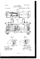
- Figure 1 is a front elevation of the feed mechanism and a portion of the framework and carbons of an arc lamp with the parts in one of the positions assumed during the normal operation, the front frame-plates being removed; Fig.2, a plan view thereof with the upper frame-plate removed; Fig. 3,a side elevation of the feed mechanism in the position assumed before the arc is drawn, with front frame-plates removed; and Figs. 4. and 5, details showing portions of the working parts in different positions assumed in the operation of the lamp, as will be explained.
- the invention is embodied in a lamp intended for use in an alternating current or under conditions in which the terminals of a lamp are at practically-constant potential.
- the feed mechanism is supported between cross-bars a a of insulating material, the lowerone of which constitutes the upper member of the lamp-frame, which comprises the side tubes?) b and lower cross-bar 6 in which the lower carbon C is supported in the usual manner, the upper carbon C being, as shown in this instance, connected with a cross-head b, which slides vertically on the side tubes 1) biand is connected by a flexible cord or band 0 with a drum 0 the rotary movement of which thus controls the vertical movement of the said upper carbon C.
- the rotary movement of the drum 0 and consequently the feed movement of the carbon C is controlled by an actuator comprising a lever d, pivoted at d in metallic upright plates a a, (see Fig.
- the said wire which is electrically connected at its upper end by a flexible conductor 3 (a copper ribbon) with the metallic framework a, in which the metallic drum 0 works.
- the current passes through the flexible support 0, which is also a conductor, being, for example, a thin ribbon of copper, to the upper carbon C, and thence through the are or directly to the lower carbon 0 and by a conductor 4 to the side post 19 and wire e, which is connected by a flexible conductor 5 with the other supporting hook h of the lamp, thus completing the circuit through the carbons and arc.
- the whole current is at all times passed through the actuator-wire which is connected by a flexible conductor 5, with the other supporting-hook 72, of the lamp, thus completing the circuit through the carbons and are.
- the whole current is at all times passed through the actuator-wire e, which would be subjected to only such variations in current as would be produced by variations in resistance at the arc; but, as before stated, such variations are not not relied upon to operate the wire e,butit is subjected to larger variations under control of the wire f, which is itself operated only by the variations in current produced by the varying resistance of the arc.
- the wire emight be produced by wholly cutting it out of circuit, so that it would receive no current at times when it was cut out, and would receive the whole currentat other times, thusmakin g very large changes of condition, which might be employed to do considerable mechanical work.
- a shunt is closed around said wire 6, said shunt consisting of another wire c which may be of any desired conductivity relative to that of the wire 6, according to the change in current required to operate the wire e, the said wire 6 for example, being of equal conductivity, so that the wire 6 receives the whole or a half of the current, according as the shunt containing the wire e is open or closed.
- the said shunt includes a circuit-closer, one member 7a of which is in the form of a lever pivoted upon a bracket but insulated from the other operative parts thus far described, and the other member of which is a projection k carried by the regulator-lever g.
- the said members 70 k are connected by wires 6 and 7, respectively, with the wire 6 and the hook 7L2, so that when the members are in contact the current from the lower carbon and post Z) will divide between the wires 6 and e in passing to the hook 7L2, so that the wire 6 will receive only a fraction of the current, which will be one-half if the wiers e and e are of equal conductivity; but when the members 70 k are separated and the shunt is open the wire 6 will receive the whole current.
- This upward and downward movement of the lever g is caused to produce corresponding feed movements of the carbon through the intervention of a pawl m, pivoted at m upon an insulating-piece d, fixed upon the free end of the lever (Z, and the said pawl m, co-operating with awheel a, connected with the drum 0 by which the carbon is lowered, the said wheel a having a roughened or toothed surface for engagement with the pawl m.
- These pawls operate in the normal feed of the lamp as follows: The retaining-pawl p is engaged and prevents feed while the pawl-carrier d is moving upward, at which time the pawl m is disengaged from its wheel, and consequently no movement of the wheel is produced, these operations occurring while the arc is about normal length, but increasing by the burning away of the carbons.
- the pawl on is engaged with the wheel and the pawl 19 disengaged, and the pawl-carrier d is caused to move downward by the contraction of the wire a, resulting from the closing of the shunt for said wire, so that the wheel is permitted to turn and the carbon lowered by the downward movement of the pawl-carrier or feed-leverd, instead of being permitted to slip and feed by gravitation, as is the case in most feed devices.
- the regulator should cause such operation of the pawls and pawl-carrier to take placethat is, while the arc is of normal length and tending to increase by the burning of the carbon it must cause or permit the pawl 19 to be engaged to prevent descent of the upper carbon, it musthold the shunt open, so that the wire will. expand and the lever d move upward, and it must cause the pawl m to be disengaged during this upward movement, so that it will not turn the wheel in the direction to raise the upper carbon and lengthen the are by drawing the carbons apart.
- the regulating-lever 9 must cause the shunt to be closed, so as to produce contraction of the wire e and downward movement of the pawl carrier, it must cause the pawl 71 to be engaged with the wheel, so as to permit the wheel to accompany it in this downward movement, and thus feed the carbon, and it must cause the pawl 12 to be disengaged, so as to permit such movement of the drum and carbon under control of the pawl m and pawl-carrier (Z.
- the engagementof pawl m is governed by a lever r, pivoted at r and provided with a weight r or an equivalent tending to turn it toward the lever g.
- the said pawl-controlling lever 1 has a cam-surface "1- that engages with a projection g on the lever g, so that the position of the' lever r is controlled by the position of the lever g.
- the lower part of said surface r is about concentric with the fulcrum of the lever g, so that the movement of the pin g along this part of the surface r does not change the position of the lever which is provided with another surface P, that engages with a projection m on the pawl m, the two surfaces 7" and r being so shaped that while the projection g is on the lower concentric part of the surface 7' the surface r does not bear upon the projection m and thus permits the pawl m to be in engagement with the wheel n.
- the lever r is provided with a projecting part 0" at the upper end of the concentric part of the surface T and when the projection 9 comes against the projection r it turns the leverron its pivot, so as to force the surface r against the projection m which throws the pawl m out of engagement with the wheel 11, as shown in Fig. 4.
- the lever Q can swing on its fulcrum from about the position shown in Fig. 3 to that shown in Fig.
- the member 70 of the shunt-circuit closer in the shunt for the actuating-wire a is pivoted in the end of the bracket 70 and is acted upon by a light spring 70 which tends to hold the said arm 7a projecting toward the path of movement of the said projection k 011 the lever 9, but permits the arm 70 to yield as the said yielding projection moves past it in either direction, the said projection and arm making electrical contact as the projection passes.
- the retaining-pawl 19 will in this movement have come into engagement with the wheel 92 so as to prevent any downward movement of the feed.
- the lever g has made its upward movement, as thus described, under the expansion of the wiref or while it is still moving the lever (Z will begin its upward movement under the expansion of the more-slowly-acting wire 6, and as the pawl m will be in engagement during the said upward movement of the lever d the wheel a will be turned in the direction to raise the upper carbon, and thus draw the are.
- a stop is provided for the lever (Z, shown as consisting of a number of shoulders I, on the pawl-controller r, that co-operate with a pivoted projection t on the arm (1 of the lever d.
- the lever cl will thus be arrested after a short upward movement sufticient to establish the arc, and the wire 6 may continue to expand, as its connection with the lever d is such that the expansion of the wire does not positively move the lever upward, but merely permits it to be moved by the spring (Z
- the stop '6 is engaged with one or the other of the shoulders 25, according to the position that the lever g and pawlcontroller r are in at the time when the lever (l rises to its uppermost position. If the lever g is very high it will permit the stop to engage one of its higher shoulders and thus effect the drawing of a longer are than takes place if the lever 9 stops in a somewhat lower position.
- any device responsive to slight changes in current might be substituted for the wire f and would be equivalent therefor, it being necessary only that such devices should produce a movement of the controlling device g in one direction upon an increase in the length of the arc and in the other direction upon a decrease in the length of the arc and that such movements should control the application of a motor-current to the actuator, which also may be any device responsive to such motor-current and capable of producing the required movements of the lever d or equivalent part co-operating with the carbon to be fed. 4
- thermostatic devices shown are responsive to alternate currents, and thus constitute a desirable form of instrument to be used when the lamp is operated by alternating currents, while being equally effective for direct currents.
- the circuit is supplied with substantially-constant current, the partsensitive to the change in the arc is, as is well known, included in a shunt around the arc, so that the current divides between the arc and the said controlling-shunt, which commonly controls the feed direct.
Landscapes
- Engineering & Computer Science (AREA)
- Physics & Mathematics (AREA)
- Plasma & Fusion (AREA)
- Mechanical Engineering (AREA)
- Radiation-Therapy Devices (AREA)
Description
(No Model I 2 SheetsSheet 1 H. H. CUTLER.
ELECTRIC ARC LAMP.
No. 482,485. Patented Sept. 13, 1892.
M Ma ma. o
;= v mum:
W7 I a w M y (No Model. z 'sneets-sheet 2.
H. H. CUTLER.
ELECTRIC ARC LAMP.
No. 482,435 Patented Septr13, 189 2.
um mlluu mm a zlw zawz r.
UNITED I STATES PATENT OFFICE HENRY H. CUTLER, OF \VALTHAM, MASSAOHUSETS.
ELECTRIC-ARC LAMP.
SPECIFICATION forming part of Letters Patent No. 482,435, dated September 13, 1892.
Application filed June 25, 1891- Serial No. 397,493. (No model.)
To all whom it may concern.-
Be it known that I, HENRY H. CUTLER, of Waltham, county of Middlesex, State of Massachusetts, have invented an Improvement in Electric Lamps, of which the following description, in connection with the accompanying drawings, is a specification, like letters on the drawings representing like parts.
My invention is embodied in the feeding mechanism of an electric-arc lamp adapted to be used either with a current of constant potential, such as employed when the lamp is operated in a shunt between'the main supplywires in the alternating-current system, or to be operated with constant current, such as is commonly used when are lamps are placed in series.
The feeding mechanism forming the subject of this invention comprises a feed-actuator connected with the carbon, by which the latter is fed positively, as required, the motive power of said actuator being derived from the current by which the light is produced, but not being dependent upon the resistance of the arc. The operation of the said actuator is controlled by a regulator, which is responsive to changes of condition of the arc and causes the feed-actuator to be operated to feed the carbons toward one another when the arc lengthens by burning away the carbons, but prevents such feed from operating when the arc is of normal length. The actuator is so connected with the carbon to be fed that at the beginning of the operation of the lamp, when the carbons are in contact, it will make a movement by which the carbons are sepa rated and the are drawn; but in the subsequent normal operation of the lamp the feedactnator does not separate or tend to separate the carbons, but merely causes them to be moved together in proportion as their points separate by the consumption of the carbon.
As herein shown, the actuator is a thermostatic device, its operation depending upon the expansion and contraction of a conductor produced by the heating ettect of the current and the cooling of the conductor When the current is removed from it, and, as shown in this instance, the thermostatic device is merely a wire which operates by direct linear expansion, such movement being very powerful, although of comparatively small amount, and in order to prevent too rapid movements the changes of condition of said thermostat are from a condition in which it carries the whole current to a condition in which it carries a portion of the current, although it is obvious that it it is desired the entire current might be removed when it is desired to operate the actuator in one direction and the entire current applied when it is desired to operate it in the other direction. The regulator is also shown in this instance as a thermostatic device included in circuit with the are, this construction being desirable when the lamp operates with constant potential, so that the current is diminished in proportion as the are lengthens. The regulator-thermostat is also a wire operating by direct linear expansion and contraction, it being always included in circuit with the are, so that as the arc lengthens the wire receives less current, becomes cooler, and consequently contracts, and when the carbons ap proach, so that the arc offers less resistance, the said wire receives more current and expands. The expansion and contraction of the regulator-thermostat is employed to operate a switch which controls the current supplied to the actuating-thermostat, the mechanism being such that when the regulator contracts, owing to the lengthening of the arc,it causes a portion of the current to be removed from the actuator, thus causing a contraction of the actuating-thermostat, in which the part connected with and moved by the actuating, thermostat moves in the direction to bring the carbons nearer together, such movement being gradual, so that no sudden changes in the are are produced.
The mechanism between the actuator and carbon is as follows: The actuating-thermostat wire connects with a lever very close to its fulcrum, said lever being provided with a spring that tends to pull it tightly against the wire, and consequently moves the lever in one direction as the wire expands and yields to permit movement of the lever in the other direction when the wire contracts. The said lever is provided with a device that engages with the carbon rod or some part connected directly with it during its movement in one direction, but not in the other. As shown in this instance, the engaging device is a pawl or friction-dog, and it engages with a wheel which has either a roughened surface or very fine ratchet-teeth to co-operate with the said pawl, and is connected with a winding-drum, to which is fastened and on which is wound a flexible support connected with the carbon, so that as the said wheel and drum are permitted to move in one direction the flexible support is paid out and the carbon permitted to descend by gravity. Such descent of the carbon is produced by the movement of the pawl-engaginglever while in engagement with the wheel, and normally when the lever is movin g in the opposite direction the pawl is disengaged from the wheel, which is at this time prevented from turning by a retaining-pawl that operates upon it or upon another wheel similarly connected with the same winding-drum. The regulator, besides operating the switch that controls the current, also mechanically operates the two pawls, causing the retainingpawl to be disengaged, while the lever-pawl is engaged and moving downward to permit the descent of the carbon, and causing the retaining-pawl to be engaged and the lever-pawl disengaged while the lever is moving upward preparatory to again engage with the wheel, so as to cause the carbon to feed again, such upward movement of the feed-lever taking place while the arc is of normal length and the carbons are burning, and thus tending to increase its length.
The device by which the regulator engages with the pawls is so constructed that when the are offers substantially no resistance, as when the lamp is beginning to operate, it affects the lever-pawl in the opposite way to that n which it is affected during the normal operation, in that at this time the lever-pawl is in engagement with the wheel during the upward movement of the lever, and thus causes the arc to be drawn.
Instead of the thermostatic devices employed to actuate the feed and to regulate the operation of the actuator electro-magnetic devices might be used for either one or both without changing the essential relations and mode of operation of the two devices, and for series lamps an electro-magnetic device in a shuntcircuit around the are will commonly be employed as the regulator.
Figure 1 is a front elevation of the feed mechanism and a portion of the framework and carbons of an arc lamp with the parts in one of the positions assumed during the normal operation, the front frame-plates being removed; Fig.2, a plan view thereof with the upper frame-plate removed; Fig. 3,a side elevation of the feed mechanism in the position assumed before the arc is drawn, with front frame-plates removed; and Figs. 4. and 5, details showing portions of the working parts in different positions assumed in the operation of the lamp, as will be explained.
As shown in Figs. 1 to 4, the invention is embodied in a lamp intended for use in an alternating current or under conditions in which the terminals of a lamp are at practically-constant potential.
The feed mechanism is supported between cross-bars a a of insulating material, the lowerone of which constitutes the upper member of the lamp-frame, which comprises the side tubes?) b and lower cross-bar 6 in which the lower carbon C is supported in the usual manner, the upper carbon C being, as shown in this instance, connected with a cross-head b, which slides vertically on the side tubes 1) biand is connected bya flexible cord or band 0 with a drum 0 the rotary movement of which thus controls the vertical movement of the said upper carbon C. The rotary movement of the drum 0 and consequently the feed movement of the carbon C, is controlled by an actuator comprising a lever d, pivoted at d in metallic upright plates a a, (see Fig. 2,) extending from one to the other of the frame-pieces a 0L and acted upon by a spring d, which tends to move the said lever in one directionas, in this instance, upward-said lever being moved in the opposite direction by the actuator proper, shown in this instance as thermostatic in character, being a wire e,extendinga sufficient distance through the interior of the tube and made fast at its lower end in said tube, the said wire being connected at its upper end with a stirrup e that engages the said lever at near its fulcrum. Thus expansion of the wire 6, which takes place when it is heated by a strong current passing through it, permits 'the lever 61 to move upward under the strain of the spring d and the contraction of said wire due to its cooling when said current or a portion thereof is removed from it causes the said lever to be moved downward, the contraction of the wire overcoming the strain of the spring (Z The application of the current to the thermostatic actuator e is governed by a regulator (shown in Fig. 1 as also thermostatic in its action) comprising a wiref, fastened at its lower end in the tube 1') and connected at its upper end with a stirrup f engaging a lever g, fulcrumed at g in the frame-pieces a a, Fig. 2, connecting the cross-bars 1 Ct at and acted upon by a spring g which moves the lever upward in proportion as the wire f expands and permits it to be moved downward as the said wire contracts.
Before describing the mechanism by which the regulator f and its lever 9 control the current which affords the motive power for the actuator e and its lever d and the mechanism by which the said lever (Z operates the feed of the carbon, the electric connections will be described and the said operative mechanism described in connection with the movements that the actuator and regulator are caused to make.
The current enters at the usual supportinghook h, passes thence by a conductor 2 to the side post I), and down the same to the lower end of the wire f, and thence back through.
the said wire, which is electrically connected at its upper end by a flexible conductor 3 (a copper ribbon) with the metallic framework a, in which the metallic drum 0 works. The current thence passes through the flexible support 0, which is also a conductor, being, for example, a thin ribbon of copper, to the upper carbon C, and thence through the are or directly to the lower carbon 0 and by a conductor 4 to the side post 19 and wire e, which is connected by a flexible conductor 5 with the other supporting hook h of the lamp, thus completing the circuit through the carbons and arc. With the connections thus far described the whole current is at all times passed through the actuator-wire which is connected by a flexible conductor 5, with the other supporting-hook 72, of the lamp, thus completing the circuit through the carbons and are. \Vith the connections thus far described the whole current is at all times passed through the actuator-wire e, which would be subjected to only such variations in current as would be produced by variations in resistance at the arc; but, as before stated, such variations are not not relied upon to operate the wire e,butit is subjected to larger variations under control of the wire f, which is itself operated only by the variations in current produced by the varying resistance of the arc. The variationsin the wire emight be produced by wholly cutting it out of circuit, so that it would receive no current at times when it was cut out, and would receive the whole currentat other times, thusmakin g very large changes of condition, which might be employed to do considerable mechanical work. As shown in this instance, instead of being wholly cut out of circuit when it is desired to cause it to contract, a shunt is closed around said wire 6, said shunt consisting of another wire c which may be of any desired conductivity relative to that of the wire 6, according to the change in current required to operate the wire e, the said wire 6 for example, being of equal conductivity, so that the wire 6 receives the whole or a half of the current, according as the shunt containing the wire e is open or closed. The said shunt includes a circuit-closer, one member 7a of which is in the form of a lever pivoted upon a bracket but insulated from the other operative parts thus far described, and the other member of which is a projection k carried by the regulator-lever g. The said members 70 k are connected by wires 6 and 7, respectively, with the wire 6 and the hook 7L2, so that when the members are in contact the current from the lower carbon and post Z) will divide between the wires 6 and e in passing to the hook 7L2, so that the wire 6 will receive only a fraction of the current, which will be one-half if the wiers e and e are of equal conductivity; but when the members 70 k are separated and the shunt is open the wire 6 will receive the whole current. Thus there will be a definite change in the current received by the wire 8, according as the shunt is open or closed, which change will be substantially uniform at all times in the operation of the lamp and will produce a substantial expansion or contraction of the wire, according as the whole or a fraction of the current traverses it, and there will thus be produced upward and downward movements of the lever d, according as the shunt is opened or closed by movements of the lever g. This upward and downward movement of the lever g is caused to produce corresponding feed movements of the carbon through the intervention of a pawl m, pivoted at m upon an insulating-piece d, fixed upon the free end of the lever (Z, and the said pawl m, co-operating with awheel a, connected with the drum 0 by which the carbon is lowered, the said wheel a having a roughened or toothed surface for engagement with the pawl m.
A second pawl 19, 00- operating with the wheel at oranother similar Wheeln connected with the drum, operates to prevent rotary movement of the drum and downward movement of the, carbon when said pawl 29 is engaged with the wheel. These pawls operate in the normal feed of the lamp as follows: The retaining-pawl p is engaged and prevents feed while the pawl-carrier d is moving upward, at which time the pawl m is disengaged from its wheel, and consequently no movement of the wheel is produced, these operations occurring while the arc is about normal length, but increasing by the burning away of the carbons. Then the pawl on is engaged with the wheel and the pawl 19 disengaged, and the pawl-carrier d is caused to move downward by the contraction of the wire a, resulting from the closing of the shunt for said wire, so that the wheel is permitted to turn and the carbon lowered by the downward movement of the pawl-carrier or feed-leverd, instead of being permitted to slip and feed by gravitation, as is the case in most feed devices. It is necessary, therefore, that the regulator should cause such operation of the pawls and pawl-carrier to take placethat is, while the arc is of normal length and tending to increase by the burning of the carbon it must cause or permit the pawl 19 to be engaged to prevent descent of the upper carbon, it musthold the shunt open, so that the wire will. expand and the lever d move upward, and it must cause the pawl m to be disengaged during this upward movement, so that it will not turn the wheel in the direction to raise the upper carbon and lengthen the are by drawing the carbons apart. Then when the arc lengthens by consumption of the carbon, so as to require the feed to take place, the regulating-lever 9 must cause the shunt to be closed, so as to produce contraction of the wire e and downward movement of the pawl carrier, it must cause the pawl 71 to be engaged with the wheel, so as to permit the wheel to accompany it in this downward movement, and thus feed the carbon, and it must cause the pawl 12 to be disengaged, so as to permit such movement of the drum and carbon under control of the pawl m and pawl-carrier (Z. The engagementof pawl m is governed by a lever r, pivoted at r and provided with a weight r or an equivalent tending to turn it toward the lever g. The said pawl-controlling lever 1 has a cam-surface "1- that engages with a projection g on the lever g, so that the position of the' lever r is controlled by the position of the lever g. The lower part of said surface r is about concentric with the fulcrum of the lever g, so that the movement of the pin g along this part of the surface r does not change the position of the lever which is provided with another surface P, that engages with a projection m on the pawl m, the two surfaces 7" and r being so shaped that while the projection g is on the lower concentric part of the surface 7' the surface r does not bear upon the projection m and thus permits the pawl m to be in engagement with the wheel n. The lever r is provided with a projecting part 0" at the upper end of the concentric part of the surface T and when the projection 9 comes against the projection r it turns the leverron its pivot, so as to force the surface r against the projection m which throws the pawl m out of engagement with the wheel 11, as shown in Fig. 4. Thus the lever Q can swing on its fulcrum from about the position shown in Fig. 3 to that shown in Fig. 1 Without changing the position of the pawl-controller T, which then stands in such position that the lever d can make its complete movement about its fulcrum with the pawl m in engagement with the wheel 91; but when the lever 9 moves far enough to bring the projection g onto the part Not the pawlcontroller, as shown in Fig. 4', it causes the pawl m to be thrown out of engagement with the wheel it whatever may be the position of the lever (Z. The same projection g that governs the pawl-controllerr,or, if preferred, another projection on the lever 9, also controls the pawl 19, which has a long projection 19 about concentric with the path of movement of the projeetiong of the lever g, which in the movement from the position shown in Fig. 3 tonearly the position shownin Fig.1 holds the pawl p out of engagement with the wheel 91 as clearly shown in Fig. 3. Just about at the moment when the projection 9 begins to act upon the projecting part 0" of the pawl-controller r, so as to move the same in the direction to disengage the pawl m from the wheel n, as shown in Fig. 4, it passes off from the arm 19 of the pawl 13 and permits the latter to come into engagement with the wheel of, so that as the projection g moves up or down from the position shown in Fig. 1 it throws the pawls m and p alternately out of engagement. These parts should be so constructed that the one pawl will come into engagement just before the other disengages, so that the wheels 01 n will always be under control of one or the other of the paw1sthat is, with the parts in the position shown in Fig. 1 both pawls are engaged and a slight upward movement of the projection g will throw the pawl m out of engagement, leaving the pawl p in engagement, while a slight downward movement will throw the pawl 19 out of engagement and leave the pawl m in engagement. The member 70 of the shunt-circuit closer in the shunt for the actuating-wire a, before mentioned, is pivoted in the end of the bracket 70 and is acted upon by a light spring 70 which tends to hold the said arm 7a projecting toward the path of movement of the said projection k 011 the lever 9, but permits the arm 70 to yield as the said yielding projection moves past it in either direction, the said projection and arm making electrical contact as the projection passes. V
The operation is as follows: \Vhen no current is flowing, the parts are in the position shown in Fig. 3, the wiresfand e being contracted and holding the levers g and (Z in their lowest position. In this position the pawl p is disengaged from the wheel a and the pawl m is also disengaged from the wheel a, which may be done by a slight rise at the lower end of the surface r or by a similar rise in the lower part of the surface T or by the stop hi as shown in Fig. 3. The wheels n n are both left free and the carbon C descends by gravity until it rests in contact with the carbon 0 The shunt for the actuator is then open at 7.1 as clearly shown in Fig. 3. When the current is turned on, it will meet no arc resistance and will flow through both wires f and e, causing the same to expand quickly. The wiref will commonly be more delicate than the wire 6, and will respond first to the current, causing the lever g to move up quickly, and as the arc is not yet drawn said wire f will receive more current than under normal condit-ions of operation of the lamp, and will rise above the position at which itnormally stands to about the position shown in Fig. 5, having passed wholly above the projecting part 1- of the pawl-carrier, and standing opposite a recessed portion 0' above the said projecting portion, and thus permitting the pawl-controller to return toward the position that permits the engagement of the pawl m with the wheel n. The retaining-pawl 19 will in this movement have come into engagement with the wheel 92 so as to prevent any downward movement of the feed. After the lever g has made its upward movement, as thus described, under the expansion of the wiref or while it is still moving the lever (Z will begin its upward movement under the expansion of the more-slowly-acting wire 6, and as the pawl m will be in engagement during the said upward movement of the lever d the wheel a will be turned in the direction to raise the upper carbon, and thus draw the are. In order to prevent too great upward movement of the carbon before the proper equilibrium is established, a stop is provided for the lever (Z, shown as consisting of a number of shoulders I, on the pawl-controller r, that co-operate with a pivoted projection t on the arm (1 of the lever d. The lever cl will thus be arrested after a short upward movement sufticient to establish the arc, and the wire 6 may continue to expand, as its connection with the lever d is such that the expansion of the wire does not positively move the lever upward, but merely permits it to be moved by the spring (Z The stop '6 is engaged with one or the other of the shoulders 25, according to the position that the lever g and pawlcontroller r are in at the time when the lever (l rises to its uppermost position. If the lever g is very high it will permit the stop to engage one of its higher shoulders and thus effect the drawing of a longer are than takes place if the lever 9 stops in a somewhat lower position. The drawing of the arc and its subsequent lengthening as the carbons burn diminishes the current in the wiref, which will thus contract somewhat and draw the lever 9 toward the position shown in Fig. 1, which is about the position in which the said lever should stand for an arc of normal length, and when the parts come to this position the normal feed of the lamp will take place, the carbons being brought together in proportion as they are consumed, as follows: The establishment of the are by the upward movement of thelever (1 causes a rather sudden diminution in the current of the wiref, which will contractand draw the lever g down from the position shown in Fig. 5 through the position shown in Fig. 4 and toward the position shown in Fig. 1, and the gradual lengthening of the are by consumption of the carbons will cause a very slow movement downward, by which it will pass below the position shown in Fig. 1, first permitting the pawl m to come in engagement with the wheel 91 while the lever 61 is still in the lifted position shown in Fig. 4 or 5, then causing the pawl p to be disengaged from the wheel 11 so that the carbon is now supported by the pawl m, and not by the pawl n, and finally the lever 9 will move far enough down to close the circuit at k ofv the shunt for the actuating-wire, thus removing the current from the said wire, which will contract and draw the lever d downward from the position shown in Fig. 5 toward that shown in Fig. 1, lowering the upper carbon and feeding the same. \Vhen such feed of the carbon is sufficient to bring the are back to normal length or a trifle less, the wire f receives more current, again causing the leverg to rise, this movement opening the shunt, as shown in Fig. 1, and thus causing more current to pass through the wire 6, the latter to expand, and the lever d to rise; but by the time that the lever d begins to rise under the effect of the increased current in the wire e the projection g has arrived on the partv' of the pawl-controller and moved the same sufficiently to throw the pawl an out of engagement with the wheel at, so that the said pawl m moves upward without turning the feed wheel, which is held from running in the other direction by the pawl p, which, as before stated, is brought into engagement just before the pawl in is disengaged. Thus in the normal operation of the lamp the lever g vibrates slowly a short distance above and below the position shown in Fig. 1, and the lever (Z also has a vibratory movement, which is controlled by and dependent upon the movement of the lever g, and although the feed is intermittent in operation, the feed movements are very slow and gradual, and a very steady arc is maintained.
' WVhile the devices herein shown as responsive to changes in current are thermostatic in their nature, depending upon the heating effect of the current, it obviously is not essential to the operative relations of these parts that they should be thermostatic in their nature.
Any device responsive to slight changes in current might be substituted for the wire f and would be equivalent therefor, it being necessary only that such devices should produce a movement of the controlling device g in one direction upon an increase in the length of the arc and in the other direction upon a decrease in the length of the arc and that such movements should control the application of a motor-current to the actuator, which also may be any device responsive to such motor-current and capable of producing the required movements of the lever d or equivalent part co-operating with the carbon to be fed. 4
Thethermostatic devices shown are responsive to alternate currents, and thus constitute a desirable form of instrument to be used when the lamp is operated by alternating currents, while being equally effective for direct currents.
\Vhen, as is the case with series lamps, the circuit is supplied with substantially-constant current, the partsensitive to the change in the arc is, as is well known, included in a shunt around the arc, so that the current divides between the arc and the said controlling-shunt, which commonly controls the feed direct.
It is obvious that the present invention is applicable to lamps operated in this manner, and persons familiar with the construction and mode of operation of the lamp will understand readily how to connect the controlling and actuating device in circuit and how to construct such controlling and actuating device for proper operation in series are lamps.
1. The combination of the carbons of an electric-arc lamp with a feed-actuator and a circuit-controller governing the application of current thereto and a thermal feed-regulator responsive to changes in length of the arc and operating the said circuitcontroller for the feed'actuator, substantially as described.
2. The combination of the feed pawl and its actuating-pawl carrier with a pawl-con- IIO troller governing the engagement of the said pawl and a regulator responsive to change in length of the arc co-operating with the said pawl-controller, substantially as and for the purpose described.
3. The combination, with the carbons of an arc lamp, of a feed-actuator comprising a thermostatic device connected in circuit and responsive to the heat produced by the current therein, a circuit-controller governing the application of current to the said thermostatic actuator, and a regulator responsive to changes in length of are operating the said circuit-controller, substantially as described.
4. The combination, with the carbons of an electric-arc lamp, of the feed-actuator whose
Publications (1)
| Publication Number | Publication Date |
|---|---|
| US482435A true US482435A (en) | 1892-09-13 |
Family
ID=2551287
Family Applications (1)
| Application Number | Title | Priority Date | Filing Date |
|---|---|---|---|
| US482435D Expired - Lifetime US482435A (en) | Electric-arc lamp |
Country Status (1)
| Country | Link |
|---|---|
| US (1) | US482435A (en) |
-
0
- US US482435D patent/US482435A/en not_active Expired - Lifetime
Similar Documents
| Publication | Publication Date | Title |
|---|---|---|
| US346430A (en) | cutten | |
| US602922A (en) | Electric-arc lamp | |
| US487315A (en) | Electric abc lamp | |
| US635851A (en) | Electric-arc lamp. | |
| US1143108A (en) | Arc-lamp. | |
| US559648A (en) | Andrew b | |
| US440662A (en) | Necticut | |
| US310736A (en) | Sidney h | |
| US302962A (en) | Electric-arc lamp | |
| US1218509A (en) | Arc-lamp. | |
| US531978A (en) | scribnee | |
| US584356A (en) | heanee | |
| US533211A (en) | Electric arc lamp | |
| US418757A (en) | sgbibner | |
| US310781A (en) | boissier | |
| US326123A (en) | Electric-arc lamp | |
| US334144A (en) | Electric arc lamp | |
| US288831A (en) | mctig-he | |
| US367568A (en) | Electric-arc lamp | |
| US452633A (en) | Electric-arc lamp | |
| US996392A (en) | Arc-lamp. | |
| US989292A (en) | Electric-arc lamp. | |
| US372986A (en) | mathis | |
| US902990A (en) | Arc-lamp. | |
| US560387A (en) | bag-nall |