US4821500A - Raking means - Google Patents
Raking means Download PDFInfo
- Publication number
- US4821500A US4821500A US07/123,050 US12305087A US4821500A US 4821500 A US4821500 A US 4821500A US 12305087 A US12305087 A US 12305087A US 4821500 A US4821500 A US 4821500A
- Authority
- US
- United States
- Prior art keywords
- tines
- gathering
- debris
- rake
- pusher
- Prior art date
- Legal status (The legal status is an assumption and is not a legal conclusion. Google has not performed a legal analysis and makes no representation as to the accuracy of the status listed.)
- Expired - Fee Related
Links
- 230000001154 acute effect Effects 0.000 claims description 3
- 244000025254 Cannabis sativa Species 0.000 abstract description 11
- 235000008331 Pinus X rigitaeda Nutrition 0.000 abstract description 8
- 235000011613 Pinus brutia Nutrition 0.000 abstract description 8
- 241000018646 Pinus brutia Species 0.000 abstract description 8
- 229910000639 Spring steel Inorganic materials 0.000 abstract description 6
- 239000012858 resilient material Substances 0.000 abstract description 2
- 238000009825 accumulation Methods 0.000 description 2
- 238000010276 construction Methods 0.000 description 2
- 235000008733 Citrus aurantifolia Nutrition 0.000 description 1
- 241000196324 Embryophyta Species 0.000 description 1
- 235000011941 Tilia x europaea Nutrition 0.000 description 1
- 238000005276 aerator Methods 0.000 description 1
- 230000000712 assembly Effects 0.000 description 1
- 238000000429 assembly Methods 0.000 description 1
- 239000003337 fertilizer Substances 0.000 description 1
- 239000004571 lime Substances 0.000 description 1
Images


Classifications
-
- A—HUMAN NECESSITIES
- A01—AGRICULTURE; FORESTRY; ANIMAL HUSBANDRY; HUNTING; TRAPPING; FISHING
- A01D—HARVESTING; MOWING
- A01D7/00—Rakes
-
- A—HUMAN NECESSITIES
- A01—AGRICULTURE; FORESTRY; ANIMAL HUSBANDRY; HUNTING; TRAPPING; FISHING
- A01D—HARVESTING; MOWING
- A01D7/00—Rakes
- A01D7/10—Rakes combined with strippers, grippers or the like
Definitions
- the present invention is a lawn rake which has been developed to make the task of raking the lawn less arduous and less time consuming.
- the lawn rake includes a frame mounted between two wheels. Two sets of tines are secured to the frame, each of which serves a distinct function.
- the rear gathering tines which are broad and closely spaced, are formed from a sheet of spring steel or other resilient material.
- the gathering tines extend downwardly and rearwardly from the frame and then curve forwardly so that the raking end of the gathering tines form an acute angle with the ground.
- the raking end of the gathering tines engage the ground to collect grass clippings, pine needles and leaves as the device is pushed forward. As the lawn rake is pulled backward, the gathering tines pass over debris which was not collected on the first pass without any accumulation on the backside thereof.
- the primary function of the front pusher tines is to keep debris in front of the gathering tines so that the gathering tines do not become clogged.
- the pusher tines are hinged to rotate forwardly when the lawn rake is pulled backward. This allows the pusher tines to pass over the debris which was collected by the gathering tines during the last forward movement. When the lawn rake is pushed forward, the pusher tines return to a substantially vertical position and keep the collected debris away from the gathering tines.
- the primary object of the present invention is to provide a lawn rake which makes the task of raking a lawn less arduous and less time consuming.
- Another object of the present invention is to provide a lawn rake which collects grass clippings, pine needles, leaves and other debris with greater efficiency than can be achieved using an ordinary hand rake.
- Another object of the present invention is to provide a lawn rake which is constructed so that the tines are less susceptible to becoming clogged with debris and thereby rendered useless until the tines are cleared of such debris.
- Another object of the present invention is to provide a lawn rake which is sturdy in construction and which has a relatively long useful life.
- FIG. 1 is a perspective view of the lawn rake of the present invention.
- FIG. 2 is a side elevational view thereof.
- FIG. 3 is a front elevational view thereof.
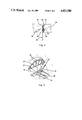
- FIG. 4 is a partial section view thereof showing the tine bar mounting bracket.
- FIG. 5 is a partial perspective view thereof.
- Lawn rake 10 includes a frame 11 supported by a pair of wheels 12. The frame 11 in turn supports two sets of tines as will be subsequently described. A handle portion 13 is secured to the frame 11 for pushing the lawn rake 10 across the lawn.
- the same includes two side plates 14 spaced approximately 30 inches apart.
- the side plates 14 have a generally trapezoidal configuration.
- An axle opening (not shown) is formed near the center of each side plate 14.
- two pairs of handle openings 16 are formed in the upper rear portion of each side plate 14 for securing handle 13 to the side plates 14.
- each side plate 14 Secured to the inside of each side plate 14, by weldment or other suitable means, is a pusher tine support plate 18.
- Axle openings (not shown) are formed in the pusher tine support plates 18 which align with axle openings in side plates 14.
- the rear end of each support plate 18 includes a bevelled upper corner which is indicated at 20.
- a tine bar opening 21 is formed in each support plate 18 between the axle opening and the bevelled corner 20.
- the purpose of the tine bar opening 20 is to support the front tine support bar 36 as will be hereinafter described.
- Frame 11 further includes a rear tine support bar 22 and a tubular member 24 which extend between and interconnect the side plates 14.
- the ends of the rear tine support bar 22 are secured to respective side plates 14 by weldment, and rest against the bevelled corners 20 of support plates 18.
- rear support bar 22 is disposed at an angle with respect to the ground.
- a series of openings are formed in the rear tine support bar 22 and spaced between the side plates 14 to allow the rear gathering tine assembly 42 to be bolted to the support bar 22.
- the tubular member 24 aligns with the axle openings in the side plates and support plates.
- the ends of the tubular member 24 are welded to respective support plates 18 as best seen in FIG. 4.
- An axle 25 is journaled within tubular member 24. The ends of the axle 25 project through the axle openings and have wheels 12 rotatively mounted thereon.
- a pair of pusher tine mounting brackets 26 interconnect the tubular member 24 and rear tine support bar 22.
- the pusher tine mounting brackets 26 include an opening 27 in the forward end thereof through which tubular member 24 extends.
- the pusher tine mounting brackets 26 further include a bevelled rear corner 28 which is welded to the rear tine support bar 22.
- a tine bar cut out 29 is formed in the lower edge of the mounting brackets 26, between the tubular member 24 and rear tine support bar 22. (See FIG. 5).
- the tine bar cut out 29 includes a generally circular upper portion 30 and a wedge shaped lower portion 31.
- the upper portion 30 has an arc-shaped edge 32 and a vertical forward edge 33.
- the lower portion 31 includes a vertical rear edge 34 and an angular front edge 35.
- a front tine support bar 36 extends through the cut-outs 29 in the mounting brackets 26.
- the front tine support bar 36 is supported by tab-like projections 37 on each end.
- the tab-like projection 37 extend into the tine bar openings 21 in respective support plates 18. If not for mounting brackets 26, the front tine support bar 36 would freely pivot in the tine bar openings 21.
- the top edge 38 of support bar 36 passes through the cut-outs 29 in mounting brackets 26, the rotation of the support bar 36 is limited.
- the rear edge 34 and vertical edge 33 of cut-outs 29 cooperate to prevent the support bar 36 from rotating backward beyond a substantially vertical position. (See FIG. 5).
- the front edge 35 of cut-outs 29 prevent the support bar 36 from swinging forward more than approximately 45 degrees.
- the gathering tine assembly 42 comprises one or more sheets of resilient spring steel having a plurality of gathering tines 43 formed along one edge thereof. A series of openings are formed along the upper edge of the gathering tine assembly 42 for bolting the tine assembly 42 to the rear tine support bar 22 as indicated at 46.
- the gathering tines 43 are formed by cutting a plurality of narrow slots 44 into the lower edge of a sheet of spring steel, which extend approximately two-thirds the distance to the upper edge. The raking ends 45 of the gathering tines 43 are pointed, thus forming, when viewed as a whole, a substantially continuous, serrated edge.
- the broad gathering tines 43 have a curved profile which define an elongated pocket on the front side of the gathering tines 43 (see FIG. 2). At the upper end, the gathering tines 43 extend downward and towards the rear of the lawn rake 10. The gathering tines 43 then curve forward so that the raking ends 45 of the gathering tines 43 project forward at an acute angle. The raking ends 45 therefore work against the ground when the lawn rake 10 is pushed forward. The forward orientation of the raking ends 45 is extremely important since it causes grass clippings, pine needles, etc., to accumulate in the elongated pocket on the front side of the gathering tines 43 when the rake is pushed forward. When the rake is pulled backward, the gathering tines 43 flex slightly upward and pass over such debris so that there is no accumulation on the back side of the gathering tines 43.
- the pusher tine assembly 46 also formed of spring steel, includes a plurality of pusher tines 47, each having a forwardly bent tip 48.
- the pusher tines 47 are spaced apart more widely than the gathering tines 43.
- a series of openings are formed along the upper edge of the pusher tine assembly 46 for bolting the same to the front tine support bar 36 as indicated at 49. It is appreciated, therefore, that the pusher tine assembly 46 will rotate with the support bar 36.
- the handle portion 14 of lawn rake 10 includes two arcuate members 50 which are secured at their lower ends to respective side plates 14.
- An intermediate tube 51 is sandwiched between the upper ends of the arcuate members 50 and secured by conventional nuts and bolts.
- the handle grip tube 52 is secured to the intermediate tube 51 by weldment and forms a tee with the intermediate tube 51.
- Handle grips 53 are placed over each end of the handle grip tube 52.
- the arcuate members 50 can be secured to the side plate 14 using either pair of handle openings 16 by a conventional bolt and wing nut assembly 55. This provides means for adjusting the height and angle of the handle portion 13. The handle adjustment can be used to accommodate different sized people or to change the amount of bite of the gathering tines 43.
- the handle grips 53 are grasped and the handle portion 13 picked up to a comfortable position.
- the lawn rake 10 is pushed forward approximately five feet then pulled rearward approximately two and one-half feet.
- the gathering tines 43 will be kept in engagement with the ground by the resiliency of the spring steel.
- the raking ends 45 will collect grass clippings, pine needles, etc., which will accumulate on the front side of the gathering tines 43 in the elongated, concave pocket.
- the gathering tines 43 When the lawn rake 10 is pulled rearward, the gathering tines will bend forward slightly. However, due to the orientation of the raking ends 45, the gathering tines 43 will pass over any debris which was left on the ground without disturbing the same and without causing the debris to accumulate on the back side of the gathering tines 43. Thus, debris which was missed on the first pass can be accumulated on the subsequent pass.
- An additional advantage of the orientation of the gathering tines 43 is that any grass clippings, pine needles or other debris which has become entangled in the gathering tines 43, will be stripped from the narrow slots 44 between the gathering tines 43 as the lawn rake 10 is pulled backward.
- the pusher tines 47 will push the majority of the load (i.e., accumulated grass clippings, pine needles, etc.) ahead of the gathering tines 43 so that the gathering tines 43 always remain free of debris.
- the pusher tines 47 are hinged to pivot forward when the lawn rake 10 is pulled backward, so that the pusher tines 47 easily pass over the debris accumulated by the gathering tines 43. After passing over the debris, the pusher tines 47 return to a substantially vertical position. In this manner, the debris which is collected by the gathering tines 43 during the forward movement is transferred to the pusher tines 47 during the next succeeding rearward movement.
- the present invention has the advantage of being relatively simple in construction yet highly efficient in removing debris from a lawn.
- the successive forward and backward movements assures that debris which is not collected on the first pass will be picked up on the subsequent pass.
- the use of a second set of tines forward of the gathering tines greatly reduces the chance that the gathering tines will become clogged with debris.
Landscapes
- Life Sciences & Earth Sciences (AREA)
- Environmental Sciences (AREA)
- Soil Working Implements (AREA)
Abstract
Description
Claims (8)
Priority Applications (1)
| Application Number | Priority Date | Filing Date | Title |
|---|---|---|---|
| US07/123,050 US4821500A (en) | 1986-11-17 | 1987-11-19 | Raking means |
Applications Claiming Priority (2)
| Application Number | Priority Date | Filing Date | Title |
|---|---|---|---|
| US90978786A | 1986-11-17 | 1986-11-17 | |
| US07/123,050 US4821500A (en) | 1986-11-17 | 1987-11-19 | Raking means |
Related Parent Applications (1)
| Application Number | Title | Priority Date | Filing Date |
|---|---|---|---|
| US90978786A Continuation-In-Part | 1986-11-17 | 1986-11-17 |
Publications (1)
| Publication Number | Publication Date |
|---|---|
| US4821500A true US4821500A (en) | 1989-04-18 |
Family
ID=26821171
Family Applications (1)
| Application Number | Title | Priority Date | Filing Date |
|---|---|---|---|
| US07/123,050 Expired - Fee Related US4821500A (en) | 1986-11-17 | 1987-11-19 | Raking means |
Country Status (1)
| Country | Link |
|---|---|
| US (1) | US4821500A (en) |
Cited By (20)
| Publication number | Priority date | Publication date | Assignee | Title |
|---|---|---|---|---|
| GB2255487A (en) * | 1991-05-09 | 1992-11-11 | Stella Marie Quesnelle | Wheeled rake. |
| US5287935A (en) * | 1992-12-09 | 1994-02-22 | Foeller Michael P | Garden weeding and landscaping tool |
| US5487260A (en) * | 1994-09-26 | 1996-01-30 | Dejay Corporation | Lawn rake |
| US5509259A (en) * | 1994-08-19 | 1996-04-23 | Milbury; Thomas | Lawn debris rake and collection device |
| US6308505B1 (en) * | 1999-12-07 | 2001-10-30 | James Beckett | Riding lawn mower leaf rake |
| US6463727B2 (en) | 1999-12-30 | 2002-10-15 | Gerald Samuel Blyth | Harvester tool |
| USD475588S1 (en) | 2002-12-03 | 2003-06-10 | Zaven S. Daniels | Hand-held yard drill/groover for planting grass seed |
| US20050028510A1 (en) * | 2003-08-07 | 2005-02-10 | Hein Vodinh | Leaf rake combo kit |
| WO2006133734A1 (en) * | 2005-06-15 | 2006-12-21 | Maria Luisa Katia Grandi | Tool particularly for gathering trash, leaves, grass and the like |
| US20110067375A1 (en) * | 2009-09-18 | 2011-03-24 | Antonio Madaffer | Rake for grooming surfaces |
| US8297034B1 (en) | 2011-08-16 | 2012-10-30 | Brett Mueller | Rolling leaf removal device |
| FR2978326A1 (en) * | 2011-07-27 | 2013-02-01 | Christian Desire Amour Goze | Rake-type device for collecting e.g. various small size dry fruits, has frame provided with teeth that exhibits reduced clearance, and flanges welded to ends of frame to retrieve fruits or debris that escape to sides |
| US20160281313A1 (en) * | 2015-03-24 | 2016-09-29 | Herman A. Lindau | Sand cleaning tool |
| USD801766S1 (en) * | 2016-09-13 | 2017-11-07 | Larry Ralph Gibson | Push rake |
| US10280577B1 (en) | 2015-03-24 | 2019-05-07 | Herman A. Lindau | Sand cleaning tool |
| US10499563B1 (en) * | 2018-08-08 | 2019-12-10 | Doug Metcalf | Jump pit sand leveling device |
| US20210076560A1 (en) * | 2019-09-17 | 2021-03-18 | Michael J. Hanrahan | An improved rake with forward facing tines |
| US11839179B1 (en) * | 2020-07-07 | 2023-12-12 | Meledey Bland | Rake |
| CN117231988A (en) * | 2023-09-14 | 2023-12-15 | 山东美森资源综合利用有限公司 | A synchronous and continuous hazardous waste incineration device and process for cement kilns |
| USD1027582S1 (en) * | 2021-05-27 | 2024-05-21 | Yeow Ng | Turf aerator tool |
Citations (11)
| Publication number | Priority date | Publication date | Assignee | Title |
|---|---|---|---|---|
| US220420A (en) * | 1879-10-07 | Improvement in ice-making apparatus | ||
| US736878A (en) * | 1903-03-04 | 1903-08-18 | August Klumpp | Rake. |
| US1014250A (en) * | 1909-09-29 | 1912-01-09 | Sterling E Norman | Rake. |
| US1591738A (en) * | 1925-09-15 | 1926-07-06 | Bell Charles Henry | Rake |
| US1768080A (en) * | 1927-12-27 | 1930-06-24 | Kurihara Yasaku | Lawn rake |
| US2065830A (en) * | 1936-02-13 | 1936-12-29 | Benjamin R Odland | Lawn rake |
| US2164233A (en) * | 1937-09-02 | 1939-06-27 | Benton E Dubbs | Self-clearing rake |
| CA454899A (en) * | 1949-03-01 | J. Stalin Joseph | Lawn rake | |
| US2463393A (en) * | 1946-07-19 | 1949-03-01 | William R Key | Lawn rake |
| US3374614A (en) * | 1965-10-20 | 1968-03-26 | Louis F. Dacheux Jr. | Self-cleaning hand rake |
| US4516393A (en) * | 1983-09-06 | 1985-05-14 | Lambert Phillip E | Wheeled push rake |
-
1987
- 1987-11-19 US US07/123,050 patent/US4821500A/en not_active Expired - Fee Related
Patent Citations (11)
| Publication number | Priority date | Publication date | Assignee | Title |
|---|---|---|---|---|
| US220420A (en) * | 1879-10-07 | Improvement in ice-making apparatus | ||
| CA454899A (en) * | 1949-03-01 | J. Stalin Joseph | Lawn rake | |
| US736878A (en) * | 1903-03-04 | 1903-08-18 | August Klumpp | Rake. |
| US1014250A (en) * | 1909-09-29 | 1912-01-09 | Sterling E Norman | Rake. |
| US1591738A (en) * | 1925-09-15 | 1926-07-06 | Bell Charles Henry | Rake |
| US1768080A (en) * | 1927-12-27 | 1930-06-24 | Kurihara Yasaku | Lawn rake |
| US2065830A (en) * | 1936-02-13 | 1936-12-29 | Benjamin R Odland | Lawn rake |
| US2164233A (en) * | 1937-09-02 | 1939-06-27 | Benton E Dubbs | Self-clearing rake |
| US2463393A (en) * | 1946-07-19 | 1949-03-01 | William R Key | Lawn rake |
| US3374614A (en) * | 1965-10-20 | 1968-03-26 | Louis F. Dacheux Jr. | Self-cleaning hand rake |
| US4516393A (en) * | 1983-09-06 | 1985-05-14 | Lambert Phillip E | Wheeled push rake |
Cited By (22)
| Publication number | Priority date | Publication date | Assignee | Title |
|---|---|---|---|---|
| GB2255487A (en) * | 1991-05-09 | 1992-11-11 | Stella Marie Quesnelle | Wheeled rake. |
| US5287935A (en) * | 1992-12-09 | 1994-02-22 | Foeller Michael P | Garden weeding and landscaping tool |
| US5509259A (en) * | 1994-08-19 | 1996-04-23 | Milbury; Thomas | Lawn debris rake and collection device |
| US5487260A (en) * | 1994-09-26 | 1996-01-30 | Dejay Corporation | Lawn rake |
| US6308505B1 (en) * | 1999-12-07 | 2001-10-30 | James Beckett | Riding lawn mower leaf rake |
| US6463727B2 (en) | 1999-12-30 | 2002-10-15 | Gerald Samuel Blyth | Harvester tool |
| USD475588S1 (en) | 2002-12-03 | 2003-06-10 | Zaven S. Daniels | Hand-held yard drill/groover for planting grass seed |
| US20050028510A1 (en) * | 2003-08-07 | 2005-02-10 | Hein Vodinh | Leaf rake combo kit |
| US6904743B2 (en) | 2003-08-07 | 2005-06-14 | Hein Vodinh | Leaf rake combo kit |
| WO2006133734A1 (en) * | 2005-06-15 | 2006-12-21 | Maria Luisa Katia Grandi | Tool particularly for gathering trash, leaves, grass and the like |
| US20110067375A1 (en) * | 2009-09-18 | 2011-03-24 | Antonio Madaffer | Rake for grooming surfaces |
| FR2978326A1 (en) * | 2011-07-27 | 2013-02-01 | Christian Desire Amour Goze | Rake-type device for collecting e.g. various small size dry fruits, has frame provided with teeth that exhibits reduced clearance, and flanges welded to ends of frame to retrieve fruits or debris that escape to sides |
| US8297034B1 (en) | 2011-08-16 | 2012-10-30 | Brett Mueller | Rolling leaf removal device |
| US20160281313A1 (en) * | 2015-03-24 | 2016-09-29 | Herman A. Lindau | Sand cleaning tool |
| US10280577B1 (en) | 2015-03-24 | 2019-05-07 | Herman A. Lindau | Sand cleaning tool |
| USD801766S1 (en) * | 2016-09-13 | 2017-11-07 | Larry Ralph Gibson | Push rake |
| US10499563B1 (en) * | 2018-08-08 | 2019-12-10 | Doug Metcalf | Jump pit sand leveling device |
| US20210076560A1 (en) * | 2019-09-17 | 2021-03-18 | Michael J. Hanrahan | An improved rake with forward facing tines |
| US11839179B1 (en) * | 2020-07-07 | 2023-12-12 | Meledey Bland | Rake |
| USD1027582S1 (en) * | 2021-05-27 | 2024-05-21 | Yeow Ng | Turf aerator tool |
| CN117231988A (en) * | 2023-09-14 | 2023-12-15 | 山东美森资源综合利用有限公司 | A synchronous and continuous hazardous waste incineration device and process for cement kilns |
| CN117231988B (en) * | 2023-09-14 | 2024-03-05 | 山东美森资源综合利用有限公司 | A synchronous and continuous hazardous waste incineration device and process for cement kilns |
Similar Documents
| Publication | Publication Date | Title |
|---|---|---|
| US4821500A (en) | Raking means | |
| US5657707A (en) | Spring-tine residue wheel for planters | |
| US4506610A (en) | Subsoil rotary cultivator | |
| US3765159A (en) | Thatch removal device | |
| CA2727374C (en) | Lawn maintenance device | |
| US5497836A (en) | Row cleaner | |
| US2689446A (en) | Side delivery rake | |
| US4245456A (en) | Rotary lawnmower with grass clearing means | |
| US6347593B1 (en) | Modular dethatcher and seeder | |
| US3859777A (en) | Thatching apparatus | |
| US5353881A (en) | Counter-rotating twin shaft system for gardening machines | |
| US5619846A (en) | Lawn mower blade | |
| US4987731A (en) | Leaf rake attachment | |
| US4635429A (en) | Windrow yard rake | |
| US5408813A (en) | Dethatching apparatus with independently rotating sets of tines | |
| US4630686A (en) | Earth scraper for use with a small tractor | |
| US4103477A (en) | Grass and leaf collector and compactor attachment for mowers | |
| US6381937B1 (en) | Cotton harvester header assembly containing paddle chain frame unit, stripper bar unit and height sensing unit | |
| US20020059790A1 (en) | Combined baler and rake apparatus | |
| US4616714A (en) | Soil perforator | |
| US7908837B2 (en) | Grass collector mounting system | |
| US5402629A (en) | Mowing machine and structure for discharged mowed grass | |
| US20040178646A1 (en) | Apparatus to assist in the collection of debris | |
| US4317327A (en) | Pushed dethatching unit | |
| US4172356A (en) | Yard rake |
Legal Events
| Date | Code | Title | Description |
|---|---|---|---|
| AS | Assignment |
Owner name: ROLL-N-RAKE, INC., A CORP. OF NC Free format text: ASSIGNMENT OF ASSIGNORS INTEREST.;ASSIGNOR:MAC IVERGAN, ROBERT G.;REEL/FRAME:005145/0770 Effective date: 19880331 |
|
| AS | Assignment |
Owner name: ROLL-N-RAKE, INC., A CORP OF NC Free format text: ASSIGNMENT OF ASSIGNORS INTEREST.;ASSIGNOR:MAC IVERGAN, ROBERT G.;REEL/FRAME:005237/0109 Effective date: 19890825 |
|
| FPAY | Fee payment |
Year of fee payment: 4 |
|
| AS | Assignment |
Owner name: LAMBERT MANUFACTURING CORPORATION, OHIO Free format text: ASSIGNMENT OF ASSIGNORS INTEREST;ASSIGNOR:ROLL-N-RAKE, INC.;REEL/FRAME:008098/0216 Effective date: 19960307 |
|
| REMI | Maintenance fee reminder mailed | ||
| FEPP | Fee payment procedure |
Free format text: PAT HOLDER CLAIMS SMALL ENTITY STATUS - SMALL BUSINESS (ORIGINAL EVENT CODE: SM02); ENTITY STATUS OF PATENT OWNER: SMALL ENTITY |
|
| FPAY | Fee payment |
Year of fee payment: 8 |
|
| SULP | Surcharge for late payment | ||
| FP | Lapsed due to failure to pay maintenance fee |
Effective date: 19970423 |
|
| REMI | Maintenance fee reminder mailed | ||
| LAPS | Lapse for failure to pay maintenance fees | ||
| FP | Lapsed due to failure to pay maintenance fee |
Effective date: 20010418 |
|
| STCH | Information on status: patent discontinuation |
Free format text: PATENT EXPIRED DUE TO NONPAYMENT OF MAINTENANCE FEES UNDER 37 CFR 1.362 |