US4818173A - Robot arm member relative movement sensing apparatus - Google Patents
Robot arm member relative movement sensing apparatus Download PDFInfo
- Publication number
- US4818173A US4818173A US06/484,228 US48422883A US4818173A US 4818173 A US4818173 A US 4818173A US 48422883 A US48422883 A US 48422883A US 4818173 A US4818173 A US 4818173A
- Authority
- US
- United States
- Prior art keywords
- light
- displacement
- photodiode
- members
- robot arm
- Prior art date
- Legal status (The legal status is an assumption and is not a legal conclusion. Google has not performed a legal analysis and makes no representation as to the accuracy of the status listed.)
- Expired - Lifetime
Links
Images


Classifications
-
- B—PERFORMING OPERATIONS; TRANSPORTING
- B25—HAND TOOLS; PORTABLE POWER-DRIVEN TOOLS; MANIPULATORS
- B25J—MANIPULATORS; CHAMBERS PROVIDED WITH MANIPULATION DEVICES
- B25J19/00—Accessories fitted to manipulators, e.g. for monitoring, for viewing; Safety devices combined with or specially adapted for use in connection with manipulators
- B25J19/02—Sensing devices
- B25J19/021—Optical sensing devices
-
- B—PERFORMING OPERATIONS; TRANSPORTING
- B25—HAND TOOLS; PORTABLE POWER-DRIVEN TOOLS; MANIPULATORS
- B25J—MANIPULATORS; CHAMBERS PROVIDED WITH MANIPULATION DEVICES
- B25J17/00—Joints
- B25J17/02—Wrist joints
- B25J17/0208—Compliance devices
Definitions
- the present invention relates to positioning apparatus, in general, and to apparatus for controlling the movement of a positioning or force generating device commonly referred to as an industrial robot, in particular.
- Industrial robots are capable of performing various mechanical operations with a high degree of speed and accuracy in response to a set of programmed instructions.
- a typical object damaging situation often occurs when an industrial robot is programmed to place a series of identical objects or piece-parts into fairly close tolerance openings or recesses in, for example, a series of identical housings, during product assembly, over an extended period of time.
- a primary object of the present invention is to provide apparatus for detecting relative movement between members that are resiliently attached to one another.
- Another object of the present invention is to provide apparatus for determining when a portion of an industrial robot arm comes in contact with a robot arm-motion impeding object.
- Another object of the present invention is to provide apparatus for terminating movement of an industrial robot whenever a portion of said robot strikes or comes in contact with a movement-impeding object.
- a further object of the present invention is to provide apparatus that will enable an industrial robot to apply a predetermined physical force to a particular object or workpiece such as when components are required to be forced together during product assembly.
- a still further object of the present invention is to provide apparatus for accurately determining the initial or null position of a robot hand for minimum time consuming, initial robot hand position-describing, robot arm programming purposes.
- apparatus for determining when a relatively movable driven member moves out of positional alignment with respect to a drive member.
- the apparatus includes means for resiliently attaching said members to one another such that they are maintained in a predetermined positional relationship relative to one another.
- An optically focused light source is mounted in a particular location on one member and a light sensitive device capable of continuously generating a member-to-member relative position signal in response to focused light from said light source striking the light sensitive surface of said light sensitive device, is mounted on the other member.
- Relative movement between said resiliently attached members causes said light sensitive device to generate an electrical signal representative of the extent of member-to-member relative movement. This signal may be employed to, for example, terminate drive member movement, cause a particular force to be applied to an object by said movable member or to facilitate the programming of a robot arm.
- FIG. 1 is a perspective view of a conventional industrial robot incorporating the relative movement sensing apparatus of the present invention.
- FIG. 2 is an enlarged elevational view, partly in section, of the relative movement sensing apparatus shown in FIG. 1.
- FIG. 3A is an exploded perspective view of the relative motion sensing apparatus shown in drawing FIG. 2.
- FIG. 3B is a sectional view, in elevation, of one of the spring-like compliant pads in the relative motion sensing apparatus of the present invention.
- FIG. 4A is a schematic diagram of the initial position of a portion of an axially misaligned piece-part inserting robot arm incorporating the relative motion sensing apparatus of the present invention.
- FIG. 4B is a schematic diagram showing the apparatus of FIG. 4 partially inserting the piece-part into a mating piece-part receiving opening.
- FIG. 5A is a schematic diagram of the initial position of a portion of a piece-part inserting robot arm holding the piece-part at an acute angle to a piece-part receiving opening.
- FIG. 5B is a schematic diagram showing the apparatus of FIG. 5A partially inserting the piece part into a mating piece-part receiving opening.
- FIG. 6A is a cross-sectional view, in schematic, of the photosensitive device employed in the relative motion sensing apparatus of the present invention.
- FIG. 6B is a schematic diagram of the external housing of a dual axis photodiode showing four external electrical connections and showing the X and Y coordinates of its light sensitive surface.
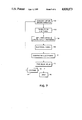
- FIG. 7 is an information flow block diagram of the motion sensing apparatus of the present invention operating in its position sensing mode of operation.
- FIG. 8 is an information flow block diagram of the motion sensing apparatus of the present invention operating in its force generating/sensing mode of operation.
- Robot arm assembly 10 is a PUMA Model 600 that is manufactured by Unimation, Inc. of Danbury, Conn.
- Robot arm assembly 10 operates in accordance with an anthropomorphic coordinate system having six degrees of freedom with portions of said assembly being capable of limited rotational movement about axes 12, 14, 16, 18 and 20.
- Robot arm assembly 10 includes pedestal 22 having pedestal axis 12 about which all of the upper portions of assembly 10 can be rotated.
- lower arm 24 which is rotatably attached to pedestal 22, is rotatable about lower arm axis 14.
- Upper arm 26 which is rotatably attached to lower arm 24, is rotatable about upper arm axis 16.
- Wrist joint 28 is rotatable about two mutually orthoginal axes 18 and 20, said joint being tiltable with respect to upper arm 26 and pivotable about axis 20 which is the axis about which pneumatically actuated workpiece-holding gripper 30 is rotated.
- Gripper 30 is resiliently attached to said wrist joint 28 by relative movement sensing apparatus 32 of the present invention. Sensing apparatus 32 senses relative movement between wrist joint 28 and work-piece holding gripper 30 and generates an electrical signal representative of such relative movement.
- Robot assembly 10 is programmed by the so-called training method, i.e., gripper 30, that is resiliently attached to upper arm 26 through sensing apparatus 32 is manually moved to the desired gripper position(s) whereupon the coordinates of this particular gripper 30 position are stored in a memory established in robot control assembly 34 for the control of robot assembly 10.
- gripper 30 that is resiliently attached to upper arm 26 through sensing apparatus 32 is manually moved to the desired gripper position(s) whereupon the coordinates of this particular gripper 30 position are stored in a memory established in robot control assembly 34 for the control of robot assembly 10.
- pneumatically actuated gripper 30 is resiliently attached to upper arm 26 through or by means of relative motion sensing apparatus 32 which incorporates the preferred embodiment of the inventive concept of the present invention.
- Relative motion sensing apparatus 32 will now be described in detail.
- An enlarged elevational view of motion sensing apparatus 32 is shown in drawing FIG. 2 and an exploded perspective view of said apparatus 32 is shown in drawing FIG. 3A.
- photodiode housing 36, lateral effect photodiode 38 and backplate 40 are attached to flange portion 42 of wrist joint 28 by a pair of mounting screws (only screw 44 shown).
- Photodiode 38 is nested in a recess in one side of housing 36 and the opposite side of housing 36 engages said flange portion 42 of wrist joint 28.
- Photodiode 38 is a conventional dual-axis (X and Y) lateral effect photodiode that is available from United Detector Technology of Culver City, Calif.
- Backplate 40 having a pair of mounting screw accepting openings 46A and 46B therein, engages the photodiode recess side of housing 36, thereby sandwiching photodiode 38 between housing 36 and backplate 40 when mounting screws 44, etc. extend through said openings 46A, 46B, through corresponding openings 48A and 48B in photodiode housing 36 and are fully threaded into cooperating threaded openings in wrist joint flange portion 42.
- Front plate 50 is resiliently mounted on back plate 40 by a set of three spring-like, laterally resilient, compliant pads (only two, 52A and 52B, are shown). These compliant pads are commercially available from Lord Kinematic of Erie, Pa. A sectional view of one of said spring-like compliant pads, pad 52A, is shown in drawing FIG. 3B.
- Pad 52A in drawing FIG. 3B consists of a plurality of flat, uniformly stacked, laminated steel disks 53A, 53B, etc., with each disk having a flat surface thereof adjacent another of said disks and with all of said disks being capsulated in an elastomeric material.
- Compliant pad 52A also includes a pair of mounting caps at the opposite ends thereof having threaded openings therein for mounting the compliant pad to back plate 40 and front plate 50.
- the ends of compliant pad 52A for example, are inserted into recesses 56A and 56B in back plate 40 and in front plate 50, respectively, and is attached to said plate by screws 58A and 58B, respectively.
- the other two compliant pads are mounted to plates 40 and 50 in different plate recesses in the same manner.
- Compliant pads 52A, 52B, etc. are relatively incompressible or will experience only negligible deformation when force is applied normal to said flat surfaces of each stacked disk, but are flexible or are deformable when shear forces are applied in directions generally lateral to said compressive forces.
- Laminated elastomeric spring-like compliant pads 52A, 52B, etc. provide multidirectional flexibility, with a chosen or tailored spring constant, in the required directions. These commercially available pads do not require lubrication, require no adjustment, have low hysteresis, can take a fair amount of abuse and have a long life.
- High intensity infrared light emitting diode 60 and optical lens 62 are mounted in a fixed position in diode/lens support housing 64.
- Other light sources such as lasers, laser diodes, non-infrared light emitting diodes or incandescent and fluorescent lamps may also be employed as light sources in place of diode 60.
- Support housing 64 is positioned in recess 66 in front plate 50 and said housing is fixedly attached to said plate 50 by screws 68A and 68B that pass through openings in tabs 70A and 70B, respectively, projecting from said housing 64 and into threaded openings in said front plate 50.
- infrared light from housing 64 mounted light emitting diode 60 is focused by conventional optical lens 62, in the shape of a relatively small circular spot, on light sensitive surface 72 of lateral effect photodiode 38.
- Pneumatic housing portion 74 of pneumatically actuated gripper 30 is attached to diode/lens support housing 64 by a pair of screws 76A and 76B that pass through openings in pneumatic housing 74 of gripper 30 and into threaded openings in said housing 64.
- Gripper 30 includes a pair of fingers 78A and 78B that move toward each other for work-piece gripping purposes when tube 80 is pressurized from a pressure source (not shown) by the actuation of a pressure control valve (not shown) in response to a signal from robot arm control system 34 (FIG. 1).
- Movement sensing apparatus 32 is, in part, a compliant device that performs around the point about which rotation will occur when a moment is applied and pure translation occurs when a force is applied to said apparatus 32.
- FIGS. 4A and 4B schematically show how lateral error is accommodated when interference is experienced by apparatus 32
- FIGS. 5A and 5B schematically show how apparatus 32 mechanically operates when there is a moment-causing axial misalignment between mating parts.
- grippers 78A and 78B attached to one end of robot arm 10 (FIG. 1) mounted relative motion sensing apparatus 32 attempts to place pin 84 in opening 86 of receiving member 88 as pin 84 is moved in axial direction 90, but is unable to initially do so because of the interference between pin 84 and champfered surface 92 at the entrance to opening 86 of receiving member 88 due to lateral misalignment of pin 84 with respect to said opening 86.
- pin 84 continues to be moved in axial direction 90, such movement and the reaction from champfered surface 92 initiate lateral movement of said pin 84, front plate 50 and support housing 62, on which light emitting diode 60 and light focusing optical lens 62 are mounted, in direction 94.
- FIG. 1 grippers 78A and 78B attached to one end of robot arm 10 (FIG. 1) mounted relative motion sensing apparatus 32 attempts to place pin 84 in opening 86 of receiving member 88 as pin 84 is moved in axial direction 90, but is unable to initially do so because of the
- pin 84 has made sufficient lateral movement to enable said pin 84 to fully enter the main portion of opening 86 in receiving member 88.
- spring-like compliant pads 52A, 52B, etc. laterally distort to enable such movement, thereby causing light from diode 60 passing through optical lens 62 and falling in the shape of a spot on photosensitive suface 72 of photodiode 38 to move to another position on said photosensitive surface 72.
- the effect of such light spot movement on the photosensitive surface of photodiode 38 will be explained below in detial. For the present, however, it is this light spot movement on said light or photosensitive surface that causes photodiode 38 to generate an electrical relative movement or position signal.
- grippers 78A and 78B attached to one end of robot arm 10 (FIG. 1) mounted relative movement sensing apparatus 32 now attempts to place said pin 84 in opening 86 of receiving member 88 as pin 84 is being moved in a direction that is at an acute angle to the longitudinal axis of opening 86. While pin 84 is able to partially enter opening 86, said pin is initially unable to fully enter opening 86 until the longitudinal axis of pin 84 is aligned (parallel and/or coincident) with the longitudinal axis of opening 86, because of the initial angular misalignment.
- pin 84 As pin 84 continues to be moved in the same direction, said pin 84, front plate 50 and support housing 64, on which light emitting diode 60 and light focusing optical lens 62 are mounted, experience rotational movement.
- pin 84 has made sufficient rotational movement about axis 96 to enable said pin 84 to fully enter opening 86 in receiving member 88.
- compliant pads 52A, 52B, etc. laterally distort to enable such rotational movement again causing causing the spot of light from light emitting diode 60 falling on photosensitive surface 72 of photodiode 38 to move to another position on said photosensitive surface, the effect of such movement, as mentioned above, is to be described below in detail.
- FIG. 6A A schematic diagram of said two-terminal photodiode 97 is shown in drawing FIG. 6A.
- the current I s at position S which is the position on photo-sensitive surface 98 of photodiode 97 where a spot of focused light from a light source falls on said surface, is given by the equation:
- the electrical signal representing the X and Y position of a light spot such as light spot 100 in said drawing FIG. 6B may be expressed as:
- motion sensing apparatus 32 can be employed in at least two different modes of operation.
- one mode changes in the relative position between the robot hand and the robot arm body are monitored for the purpose of interrupting or terminating robot arm movement due to robot arm interference.
- Another mode of operation changes in the relative position of the robot hand (gripper 30) and the robot arm body are monitored for the purpose of sensing inertial forces or for applying a force to a body of a predetermined magnitude.
- FIG. 7 shows an information flow block diagram of the motion sensing apparatus of the present invention operating in the robot arm motion interrupting mode.
- This signal is compared with predetermined X and Y electrical signal levels (110) and then signal presence in excess of a minimum time duration (112) is determined to filter out false or unwanted mechanical vibrations. If the X or Y signals are less than the predetermined magnitude or are shorter than the predetermined time, the motion sensing apparatus will continue to monitor relative robot hand (gripper) to robot arm body relative movement (114) without interrupting robot arm movement. However, if the X or Y translation signals are more than the predetermined magnitude and persist for more than a predetermined time, compliant motion sensing apparatus 32 will cause robot arm motion to be interrupted (116).
- FIG. 8 shows the information flow block diagram of motion sensing apparatus 32 of the present invention operating in the robot arm force providing mode.
- pin 84 should be brought into contact with a portion of fixedly mounted receiving member 88 by the lateral movement of robot arm assembly 10 (FIG. 1), pin 84 together with front plate 50 of motion sensing apparatus 32 will be laterally displaced or translated in an X and/or Y direction (118) against the tailored or chosen force of compliant pads 52A, 52B, etc.
- This relative movement produces an electrical signal (128) representative of such X and/or Y movement.
- the signal is compared with desired X and/or Y electrical signal levels (130) whose magnitude(s) corresponds to a desired predetermined force.
- Forces that are generated by the robot arm result from robot arm deflection of compliant pads 52A, 52B, etc., having a known spring constant, a particular distance "d". The deflection of these compliant pads continues (132) until the desired predetermined force is established. Once the force is established, robot arm motion is terminated (134) and the force is maintained.
- motion sensing appartaus 32 can also be employed to determine the null or neutral position of robot hand or gripper 30. By monitoring the current of lateral effect photodiode 32 it is possible to precisely determine said null position which can greatly reduce robot arm programming time.
Landscapes
- Engineering & Computer Science (AREA)
- Robotics (AREA)
- Mechanical Engineering (AREA)
- Manipulator (AREA)
- Length Measuring Devices By Optical Means (AREA)
Abstract
Description
I.sub.s =I.sub.O (I-S/L)
X position=A-C/A+C
Y position=B-D/B+D
Claims (19)
Priority Applications (5)
| Application Number | Priority Date | Filing Date | Title |
|---|---|---|---|
| US06/484,228 US4818173A (en) | 1983-04-12 | 1983-04-12 | Robot arm member relative movement sensing apparatus |
| EP84302281A EP0125775B1 (en) | 1983-04-12 | 1984-04-03 | Controlling movement of a robot arm |
| DE8484302281T DE3470011D1 (en) | 1983-04-12 | 1984-04-03 | Controlling movement of a robot arm |
| CA000451545A CA1237180A (en) | 1983-04-12 | 1984-04-09 | Robot arm member relative movement sensing apparatus |
| JP59071074A JPS59206730A (en) | 1983-04-12 | 1984-04-11 | Detector for load force |
Applications Claiming Priority (1)
| Application Number | Priority Date | Filing Date | Title |
|---|---|---|---|
| US06/484,228 US4818173A (en) | 1983-04-12 | 1983-04-12 | Robot arm member relative movement sensing apparatus |
Publications (1)
| Publication Number | Publication Date |
|---|---|
| US4818173A true US4818173A (en) | 1989-04-04 |
Family
ID=23923282
Family Applications (1)
| Application Number | Title | Priority Date | Filing Date |
|---|---|---|---|
| US06/484,228 Expired - Lifetime US4818173A (en) | 1983-04-12 | 1983-04-12 | Robot arm member relative movement sensing apparatus |
Country Status (5)
| Country | Link |
|---|---|
| US (1) | US4818173A (en) |
| EP (1) | EP0125775B1 (en) |
| JP (1) | JPS59206730A (en) |
| CA (1) | CA1237180A (en) |
| DE (1) | DE3470011D1 (en) |
Cited By (26)
| Publication number | Priority date | Publication date | Assignee | Title |
|---|---|---|---|---|
| US5098024A (en) * | 1990-07-27 | 1992-03-24 | Northrop Corporation | Spray end effector |
| US5142930A (en) * | 1987-11-10 | 1992-09-01 | Allen George S | Interactive image-guided surgical system |
| US5194791A (en) * | 1990-07-19 | 1993-03-16 | Mcdonnell Douglas Corporation | Compliant stereo vision target |
| US5269070A (en) * | 1992-10-19 | 1993-12-14 | Thurston Wm H | Instrument for measuring flatness or uniformity of curvature |
| US5383368A (en) * | 1992-11-16 | 1995-01-24 | Southwest Research Institute | Deflection sensor for robot links |
| US20020141899A1 (en) * | 2000-09-28 | 2002-10-03 | Fu-Pao Tsao | Compositions and methods for cleaning contact lenses |
| US6530735B1 (en) * | 2000-06-22 | 2003-03-11 | Amkor Technology, Inc. | Gripper assembly |
| US20030119684A1 (en) * | 2001-11-21 | 2003-06-26 | Fu-Pao Tsao | Conditioning solution for contact lenses and a method of using the same |
| US6695120B1 (en) | 2000-06-22 | 2004-02-24 | Amkor Technology, Inc. | Assembly for transporting material |
| US20040066514A1 (en) * | 2002-10-08 | 2004-04-08 | Kardos Victor J. | Upper compliant tooling |
| EP1431008A3 (en) * | 2002-12-18 | 2004-12-08 | IMI NORGREN Automotive GmbH | Tooling system to be used with a robot |
| US6880237B2 (en) * | 2000-03-15 | 2005-04-19 | Kazuhiro Kosuge | Work chucking/inserting apparatus and assembling unit |
| US6889813B1 (en) | 2000-06-22 | 2005-05-10 | Amkor Technology, Inc. | Material transport method |
| US20060119026A1 (en) * | 2004-12-07 | 2006-06-08 | Ryaboy Vyacheslav M | Methods and devices for active vibration damping of an optical structure |
| US7320455B2 (en) | 2003-10-24 | 2008-01-22 | Newport Corporation | Instrumented platform for vibration-sensitive equipment |
| US20090088899A1 (en) * | 2005-09-16 | 2009-04-02 | Abb Ab | Industrial robot |
| US20090099688A1 (en) * | 2005-11-10 | 2009-04-16 | Hugo Salamanca | Integral robot system and method for the dislodging process and/or anode handling from casting wheels |
| US20090121061A1 (en) * | 2005-11-10 | 2009-05-14 | Hugo Salamanca | Robot system and method for unblocking the primary crusher |
| US20090177324A1 (en) * | 2005-11-10 | 2009-07-09 | Hugo Salamanca | Robot system and method for maxibags sampling in ore concentration processes |
| US20100109360A1 (en) * | 2008-10-30 | 2010-05-06 | Canon Kabushiki Kaisha | Gripping device and system including the same |
| US7746018B2 (en) | 2005-11-10 | 2010-06-29 | MI Robotic Solutions | Robot system and method for reposition and/or removal of base plates from cathode stripping machines in electrometallurgical processes |
| US8857585B2 (en) | 2010-12-29 | 2014-10-14 | Newport Corporation | Tunable vibration dampers and methods of manufacture and tuning |
| US8936289B1 (en) * | 2010-03-15 | 2015-01-20 | Telefactor Robotics LLC | Robotic finger assemblies |
| US20180200892A1 (en) * | 2017-01-19 | 2018-07-19 | Seiko Epson Corporation | Robot |
| US10618174B2 (en) | 2014-12-09 | 2020-04-14 | Aeolus Robotics, Inc. | Robotic Touch Perception |
| CN113696222A (en) * | 2021-08-27 | 2021-11-26 | 张金燕 | Industrial robot and application thereof in printing production |
Families Citing this family (5)
| Publication number | Priority date | Publication date | Assignee | Title |
|---|---|---|---|---|
| JPS61284624A (en) * | 1985-06-07 | 1986-12-15 | テクトロニツクス・インコ−ポレイテツド | Pressure sensitive controller |
| FR2630956A1 (en) * | 1988-05-03 | 1989-11-10 | Afma Robots | ELASTICALLY DEFORMABLE CONNECTION DEVICE WITH SECURITY THRESHOLD OF AT LEAST TWO MOVABLE PARTS TOGETHER |
| GB9105287D0 (en) * | 1991-03-13 | 1991-04-24 | Greenhill Richard | Artificial digit |
| DE4143211A1 (en) * | 1991-12-30 | 1993-07-01 | Fischer Gernot E | Manipulation arrangement with positioning unit - contains position error compensation or compliance element, control unit with stored manipulation movements. |
| CN118721184B (en) * | 2024-06-14 | 2025-10-03 | 杭州电子科技大学 | Adaptive manipulator human-machine-object transmission method, system, machine-readable storage medium and data processing device based on point cloud under composite constraints |
Citations (11)
| Publication number | Priority date | Publication date | Assignee | Title |
|---|---|---|---|---|
| US2317632A (en) * | 1939-07-20 | 1943-04-27 | Eastman Oil Well Survey Co | Means for surveying well bores |
| US2792637A (en) * | 1952-01-15 | 1957-05-21 | Newmont Mining Corp | Apparatus for surveying drill holes |
| US3526748A (en) * | 1968-08-02 | 1970-09-01 | Gen Dynamics Corp | Optical monitoring of welding systems |
| US3703682A (en) * | 1968-10-30 | 1972-11-21 | Us Navy | Long axis gradiometer |
| US3824674A (en) * | 1972-07-19 | 1974-07-23 | Hitachi Ltd | Automatic assembly control method and device therefor |
| US3918814A (en) * | 1974-05-13 | 1975-11-11 | Weiser Robodyne Corp | Optical position sensor |
| US4076131A (en) * | 1975-06-16 | 1978-02-28 | Allmanna Svenska Elektriska Aktiebolaget | Industrial robot |
| US4179783A (en) * | 1974-12-16 | 1979-12-25 | Hitachi, Ltd. | Holding apparatus with elastic mechanism |
| US4309618A (en) * | 1980-05-05 | 1982-01-05 | Bell Telephone Laboratories, Incorporated | Precision optical distance measurement |
| US4330204A (en) * | 1979-11-16 | 1982-05-18 | Santa Barbara Research Center | Self-aligning laser communicator utilizing reciprocal tracking |
| US4445029A (en) * | 1980-06-16 | 1984-04-24 | Seiko Koki Kabushiki Kaisha | Distance detector using a photopotentiometer and a continuous detecting system |
Family Cites Families (5)
| Publication number | Priority date | Publication date | Assignee | Title |
|---|---|---|---|---|
| GB1511265A (en) * | 1974-05-31 | 1978-05-17 | Nasa | Apparatus for sensing the relative position of two object |
| CH611196A5 (en) * | 1976-09-27 | 1979-05-31 | Int De Rech Tech Et De Consule | |
| US4362977A (en) * | 1980-06-30 | 1982-12-07 | International Business Machines Corporation | Method and apparatus for calibrating a robot to compensate for inaccuracy of the robot |
| JPS59353B2 (en) * | 1980-07-24 | 1984-01-06 | ファナック株式会社 | gripping device |
| JPS5810495A (en) * | 1981-07-14 | 1983-01-21 | 日産自動車株式会社 | Tactile sensor |
-
1983
- 1983-04-12 US US06/484,228 patent/US4818173A/en not_active Expired - Lifetime
-
1984
- 1984-04-03 DE DE8484302281T patent/DE3470011D1/en not_active Expired
- 1984-04-03 EP EP84302281A patent/EP0125775B1/en not_active Expired
- 1984-04-09 CA CA000451545A patent/CA1237180A/en not_active Expired
- 1984-04-11 JP JP59071074A patent/JPS59206730A/en active Pending
Patent Citations (11)
| Publication number | Priority date | Publication date | Assignee | Title |
|---|---|---|---|---|
| US2317632A (en) * | 1939-07-20 | 1943-04-27 | Eastman Oil Well Survey Co | Means for surveying well bores |
| US2792637A (en) * | 1952-01-15 | 1957-05-21 | Newmont Mining Corp | Apparatus for surveying drill holes |
| US3526748A (en) * | 1968-08-02 | 1970-09-01 | Gen Dynamics Corp | Optical monitoring of welding systems |
| US3703682A (en) * | 1968-10-30 | 1972-11-21 | Us Navy | Long axis gradiometer |
| US3824674A (en) * | 1972-07-19 | 1974-07-23 | Hitachi Ltd | Automatic assembly control method and device therefor |
| US3918814A (en) * | 1974-05-13 | 1975-11-11 | Weiser Robodyne Corp | Optical position sensor |
| US4179783A (en) * | 1974-12-16 | 1979-12-25 | Hitachi, Ltd. | Holding apparatus with elastic mechanism |
| US4076131A (en) * | 1975-06-16 | 1978-02-28 | Allmanna Svenska Elektriska Aktiebolaget | Industrial robot |
| US4330204A (en) * | 1979-11-16 | 1982-05-18 | Santa Barbara Research Center | Self-aligning laser communicator utilizing reciprocal tracking |
| US4309618A (en) * | 1980-05-05 | 1982-01-05 | Bell Telephone Laboratories, Incorporated | Precision optical distance measurement |
| US4445029A (en) * | 1980-06-16 | 1984-04-24 | Seiko Koki Kabushiki Kaisha | Distance detector using a photopotentiometer and a continuous detecting system |
Non-Patent Citations (2)
| Title |
|---|
| IBM Technical Disclosure Bulletin, "Position Detecting Apparatus", H. R. Rottman, vol. 9, #5, Oct. 1966. |
| IBM Technical Disclosure Bulletin, Position Detecting Apparatus , H. R. Rottman, vol. 9, 5, Oct. 1966. * |
Cited By (36)
| Publication number | Priority date | Publication date | Assignee | Title |
|---|---|---|---|---|
| US5142930A (en) * | 1987-11-10 | 1992-09-01 | Allen George S | Interactive image-guided surgical system |
| US5230338A (en) * | 1987-11-10 | 1993-07-27 | Allen George S | Interactive image-guided surgical system for displaying images corresponding to the placement of a surgical tool or the like |
| US5194791A (en) * | 1990-07-19 | 1993-03-16 | Mcdonnell Douglas Corporation | Compliant stereo vision target |
| US5098024A (en) * | 1990-07-27 | 1992-03-24 | Northrop Corporation | Spray end effector |
| US5269070A (en) * | 1992-10-19 | 1993-12-14 | Thurston Wm H | Instrument for measuring flatness or uniformity of curvature |
| US5383368A (en) * | 1992-11-16 | 1995-01-24 | Southwest Research Institute | Deflection sensor for robot links |
| US6880237B2 (en) * | 2000-03-15 | 2005-04-19 | Kazuhiro Kosuge | Work chucking/inserting apparatus and assembling unit |
| US6530735B1 (en) * | 2000-06-22 | 2003-03-11 | Amkor Technology, Inc. | Gripper assembly |
| US6695120B1 (en) | 2000-06-22 | 2004-02-24 | Amkor Technology, Inc. | Assembly for transporting material |
| US6889813B1 (en) | 2000-06-22 | 2005-05-10 | Amkor Technology, Inc. | Material transport method |
| US20020141899A1 (en) * | 2000-09-28 | 2002-10-03 | Fu-Pao Tsao | Compositions and methods for cleaning contact lenses |
| US20030119684A1 (en) * | 2001-11-21 | 2003-06-26 | Fu-Pao Tsao | Conditioning solution for contact lenses and a method of using the same |
| US20040066514A1 (en) * | 2002-10-08 | 2004-04-08 | Kardos Victor J. | Upper compliant tooling |
| EP1431008A3 (en) * | 2002-12-18 | 2004-12-08 | IMI NORGREN Automotive GmbH | Tooling system to be used with a robot |
| US7320455B2 (en) | 2003-10-24 | 2008-01-22 | Newport Corporation | Instrumented platform for vibration-sensitive equipment |
| US20060119026A1 (en) * | 2004-12-07 | 2006-06-08 | Ryaboy Vyacheslav M | Methods and devices for active vibration damping of an optical structure |
| US8651447B2 (en) | 2004-12-07 | 2014-02-18 | Newport Corporation | Methods and devices for active vibration damping of an optical structure |
| US8231098B2 (en) | 2004-12-07 | 2012-07-31 | Newport Corporation | Methods and devices for active vibration damping of an optical structure |
| US20090088899A1 (en) * | 2005-09-16 | 2009-04-02 | Abb Ab | Industrial robot |
| US7707893B2 (en) * | 2005-09-16 | 2010-05-04 | Abb Ab | Industrial robot |
| US20090121061A1 (en) * | 2005-11-10 | 2009-05-14 | Hugo Salamanca | Robot system and method for unblocking the primary crusher |
| US7746018B2 (en) | 2005-11-10 | 2010-06-29 | MI Robotic Solutions | Robot system and method for reposition and/or removal of base plates from cathode stripping machines in electrometallurgical processes |
| US20090177324A1 (en) * | 2005-11-10 | 2009-07-09 | Hugo Salamanca | Robot system and method for maxibags sampling in ore concentration processes |
| US20090099688A1 (en) * | 2005-11-10 | 2009-04-16 | Hugo Salamanca | Integral robot system and method for the dislodging process and/or anode handling from casting wheels |
| US20100109360A1 (en) * | 2008-10-30 | 2010-05-06 | Canon Kabushiki Kaisha | Gripping device and system including the same |
| US8182197B2 (en) * | 2008-10-30 | 2012-05-22 | Canon Kabushiki Kaisha | Gripping device and system including the same |
| US8936289B1 (en) * | 2010-03-15 | 2015-01-20 | Telefactor Robotics LLC | Robotic finger assemblies |
| US9469036B1 (en) | 2010-03-15 | 2016-10-18 | Telefactor Robotics LLC | Robotic finger assemblies |
| US10099388B1 (en) | 2010-03-15 | 2018-10-16 | Telefactor Robotics LLC | Robotic finger assemblies |
| US8857585B2 (en) | 2010-12-29 | 2014-10-14 | Newport Corporation | Tunable vibration dampers and methods of manufacture and tuning |
| US10618174B2 (en) | 2014-12-09 | 2020-04-14 | Aeolus Robotics, Inc. | Robotic Touch Perception |
| US11345039B2 (en) | 2014-12-09 | 2022-05-31 | Aeolus Robotics, Inc. | Robotic touch perception |
| US11839984B2 (en) | 2014-12-09 | 2023-12-12 | Aeolus Robotics, Inc. | Robotic touch perception |
| US20180200892A1 (en) * | 2017-01-19 | 2018-07-19 | Seiko Epson Corporation | Robot |
| CN113696222A (en) * | 2021-08-27 | 2021-11-26 | 张金燕 | Industrial robot and application thereof in printing production |
| CN113696222B (en) * | 2021-08-27 | 2022-12-16 | 张金燕 | Industrial robot and application thereof in printing production |
Also Published As
| Publication number | Publication date |
|---|---|
| CA1237180A (en) | 1988-05-24 |
| EP0125775B1 (en) | 1988-03-23 |
| EP0125775A3 (en) | 1984-12-27 |
| DE3470011D1 (en) | 1988-04-28 |
| EP0125775A2 (en) | 1984-11-21 |
| JPS59206730A (en) | 1984-11-22 |
Similar Documents
| Publication | Publication Date | Title |
|---|---|---|
| US4818173A (en) | Robot arm member relative movement sensing apparatus | |
| US4818174A (en) | Compact robot arm member relative movement sensor | |
| US4627169A (en) | Remote center compliance device | |
| US8215199B2 (en) | Parallel kinematic positioning system | |
| CN111015733B (en) | Attachment mechanism, robot device, and attachment method | |
| US4919586A (en) | Mechanical closed loop robotic arm end effector positioning system | |
| Koseki et al. | Design and accuracy evaluation of high-speed and high precision parallel mechanism | |
| EP0227231A1 (en) | Robot tool changing apparatus | |
| US4741642A (en) | Safety joint for robotic arm | |
| JPS6355418B2 (en) | ||
| ATE41344T1 (en) | AUTOMATIC TOOL CHANGER FOR INDUSTRIAL ROBOTS. | |
| US4573271A (en) | Machine performance sensor | |
| WO1988001555A1 (en) | Robot overload detection mechanism | |
| US5714674A (en) | Reference position determination method for industrial robot | |
| Chan et al. | A reconfigurable fixturing system for robotic assembly | |
| US4485562A (en) | Variable stiffness compliance device | |
| KR20190120838A (en) | Robot manipulator | |
| CN112873203B (en) | Omnidirectional Parts Assembly Error Adaptive Compensation System | |
| KR20230172931A (en) | Underactuated finger module, gripper including the same, and bending control method of underactuaede finger module | |
| KR100424327B1 (en) | Method and apparatus for automatic position-finding assembling | |
| JP7207886B2 (en) | Sensor, sensor control method, robot hand, robot hand control method, robot device, article control method using robot device, structure, control program, and recording medium | |
| JPS601994Y2 (en) | External contact detection device | |
| Frye et al. | Dexterous Assembly Using a Planar Hand Having Programmable Passive Compliance | |
| CN216731853U (en) | End actuating device and mechanical arm | |
| US4708383A (en) | Manipulator gripper tool |
Legal Events
| Date | Code | Title | Description |
|---|---|---|---|
| AS | Assignment |
Owner name: POLARIOD CORPORATION, 549 TECHNOLOGY SQ., CAMBRIDG Free format text: ASSIGNMENT OF ASSIGNORS INTEREST.;ASSIGNOR:KHUSRO, MOHAMMED M.;REEL/FRAME:004119/0998 Effective date: 19830331 |
|
| STCF | Information on status: patent grant |
Free format text: PATENTED CASE |
|
| FPAY | Fee payment |
Year of fee payment: 4 |
|
| FPAY | Fee payment |
Year of fee payment: 8 |
|
| FPAY | Fee payment |
Year of fee payment: 12 |
|
| AS | Assignment |
Owner name: MORGAN GUARANTY TRUST COMPANY OF NEW YORK, NEW YOR Free format text: SECURITY AGREEMENT;ASSIGNOR:POLAROID CORPORATION;REEL/FRAME:011658/0699 Effective date: 20010321 |
|
| AS | Assignment |
Owner name: OEP IMAGINIG OPERATING CORPORATION, NEW YORK Free format text: ASSIGNMENT OF ASSIGNORS INTEREST;ASSIGNOR:POLAROID CORPORATION;REEL/FRAME:016427/0144 Effective date: 20020731 Owner name: POLAROID CORPORATION, NEW YORK Free format text: CHANGE OF NAME;ASSIGNOR:OEP IMAGING OPERATING CORPORATION;REEL/FRAME:016470/0006 Effective date: 20020801 Owner name: OEP IMAGINIG OPERATING CORPORATION,NEW YORK Free format text: ASSIGNMENT OF ASSIGNORS INTEREST;ASSIGNOR:POLAROID CORPORATION;REEL/FRAME:016427/0144 Effective date: 20020731 Owner name: POLAROID CORPORATION,NEW YORK Free format text: CHANGE OF NAME;ASSIGNOR:OEP IMAGING OPERATING CORPORATION;REEL/FRAME:016470/0006 Effective date: 20020801 |
|
| AS | Assignment |
Owner name: WILMINGTON TRUST COMPANY, AS COLLATERAL AGENT, DEL Free format text: ASSIGNMENT OF ASSIGNORS INTEREST;ASSIGNORS:POLAROLD HOLDING COMPANY;POLAROID CORPORATION;POLAROID ASIA PACIFIC LLC;AND OTHERS;REEL/FRAME:016602/0332 Effective date: 20050428 Owner name: JPMORGAN CHASE BANK,N.A,AS ADMINISTRATIVE AGENT, W Free format text: SECURITY INTEREST;ASSIGNORS:POLAROID HOLDING COMPANY;POLAROID CORPORATION;POLAROID ASIA PACIFIC LLC;AND OTHERS;REEL/FRAME:016602/0603 Effective date: 20050428 Owner name: WILMINGTON TRUST COMPANY, AS COLLATERAL AGENT,DELA Free format text: SECURITY AGREEMENT;ASSIGNORS:POLAROLD HOLDING COMPANY;POLAROID CORPORATION;POLAROID ASIA PACIFIC LLC;AND OTHERS;REEL/FRAME:016602/0332 Effective date: 20050428 Owner name: JPMORGAN CHASE BANK,N.A,AS ADMINISTRATIVE AGENT,WI Free format text: SECURITY INTEREST;ASSIGNORS:POLAROID HOLDING COMPANY;POLAROID CORPORATION;POLAROID ASIA PACIFIC LLC;AND OTHERS;REEL/FRAME:016602/0603 Effective date: 20050428 Owner name: WILMINGTON TRUST COMPANY, AS COLLATERAL AGENT, DEL Free format text: SECURITY AGREEMENT;ASSIGNORS:POLAROLD HOLDING COMPANY;POLAROID CORPORATION;POLAROID ASIA PACIFIC LLC;AND OTHERS;REEL/FRAME:016602/0332 Effective date: 20050428 |
|
| AS | Assignment |
Owner name: POLAROID CORPORATION (F/K/A OEP IMAGING OPERATING Free format text: U.S. BANKRUPTCY COURT DISTRICT OF DELAWARE ORDER AUTHORIZING RELEASE OF ALL LIENS;ASSIGNOR:JPMORGAN CHASE BANK, N.A. (F/K/A MORGAN GUARANTY TRUST COMPANY OF NEW YORK);REEL/FRAME:016621/0377 Effective date: 20020418 Owner name: POLAROID CORPORATION (F/K/A OEP IMAGING OPERATING COMPANY), MASSACHUSETTS Free format text: U.S. BANKRUPTCY COURT DISTRICT OF DELAWARE ORDER AUTHORIZING RELEASE OF ALL LIENS;ASSIGNOR:JPMORGAN CHASE BANK, N.A. (F/K/A MORGAN GUARANTY TRUST COMPANY OF NEW YORK);REEL/FRAME:016621/0377 Effective date: 20020418 |
|
| AS | Assignment |
Owner name: OEP IMAGING OPERATING CORPORATION,NEW YORK Free format text: ASSIGNMENT OF ASSIGNORS INTEREST;ASSIGNOR:POLAROID CORPORATION;REEL/FRAME:018584/0600 Effective date: 20020731 Owner name: OEP IMAGING OPERATING CORPORATION, NEW YORK Free format text: ASSIGNMENT OF ASSIGNORS INTEREST;ASSIGNOR:POLAROID CORPORATION;REEL/FRAME:018584/0600 Effective date: 20020731 |
|
| AS | Assignment |
Owner name: POLAROID CORPORATION (FMR OEP IMAGING OPERATING CO Free format text: SUPPLEMENTAL ASSIGNMENT OF PATENTS;ASSIGNOR:PRIMARY PDC, INC. (FMR POLAROID CORPORATION);REEL/FRAME:019077/0001 Effective date: 20070122 Owner name: POLAROID CORPORATION (FMR OEP IMAGING OPERATING CORP.), MASSACHUSETTS Free format text: SUPPLEMENTAL ASSIGNMENT OF PATENTS;ASSIGNOR:PRIMARY PDC, INC. (FMR POLAROID CORPORATION);REEL/FRAME:019077/0001 Effective date: 20070122 |
|
| AS | Assignment |
Owner name: POLAROID HOLDING COMPANY, MASSACHUSETTS Free format text: RELEASE OF SECURITY INTEREST IN PATENTS;ASSIGNOR:WILMINGTON TRUST COMPANY;REEL/FRAME:019699/0512 Effective date: 20070425 Owner name: POLAROID CORPORATION, MASSACHUSETTS Free format text: RELEASE OF SECURITY INTEREST IN PATENTS;ASSIGNOR:WILMINGTON TRUST COMPANY;REEL/FRAME:019699/0512 Effective date: 20070425 Owner name: POLAROID CAPITAL LLC, MASSACHUSETTS Free format text: RELEASE OF SECURITY INTEREST IN PATENTS;ASSIGNOR:WILMINGTON TRUST COMPANY;REEL/FRAME:019699/0512 Effective date: 20070425 Owner name: POLAROID ASIA PACIFIC LLC, MASSACHUSETTS Free format text: RELEASE OF SECURITY INTEREST IN PATENTS;ASSIGNOR:WILMINGTON TRUST COMPANY;REEL/FRAME:019699/0512 Effective date: 20070425 Owner name: POLAROID EYEWEAR LLC, MASSACHUSETTS Free format text: RELEASE OF SECURITY INTEREST IN PATENTS;ASSIGNOR:WILMINGTON TRUST COMPANY;REEL/FRAME:019699/0512 Effective date: 20070425 Owner name: POLOROID INTERNATIONAL HOLDING LLC, MASSACHUSETTS Free format text: RELEASE OF SECURITY INTEREST IN PATENTS;ASSIGNOR:WILMINGTON TRUST COMPANY;REEL/FRAME:019699/0512 Effective date: 20070425 Owner name: POLAROID INVESTMENT LLC, MASSACHUSETTS Free format text: RELEASE OF SECURITY INTEREST IN PATENTS;ASSIGNOR:WILMINGTON TRUST COMPANY;REEL/FRAME:019699/0512 Effective date: 20070425 Owner name: POLAROID LATIN AMERICA I CORPORATION, MASSACHUSETT Free format text: RELEASE OF SECURITY INTEREST IN PATENTS;ASSIGNOR:WILMINGTON TRUST COMPANY;REEL/FRAME:019699/0512 Effective date: 20070425 Owner name: POLAROID NEW BEDFORD REAL ESTATE LLC, MASSACHUSETT Free format text: RELEASE OF SECURITY INTEREST IN PATENTS;ASSIGNOR:WILMINGTON TRUST COMPANY;REEL/FRAME:019699/0512 Effective date: 20070425 Owner name: POLAROID NORWOOD REAL ESTATE LLC, MASSACHUSETTS Free format text: RELEASE OF SECURITY INTEREST IN PATENTS;ASSIGNOR:WILMINGTON TRUST COMPANY;REEL/FRAME:019699/0512 Effective date: 20070425 Owner name: POLAROID WALTHAM REAL ESTATE LLC, MASSACHUSETTS Free format text: RELEASE OF SECURITY INTEREST IN PATENTS;ASSIGNOR:WILMINGTON TRUST COMPANY;REEL/FRAME:019699/0512 Effective date: 20070425 Owner name: PETTERS CONSUMER BRANDS, LLC, MASSACHUSETTS Free format text: RELEASE OF SECURITY INTEREST IN PATENTS;ASSIGNOR:WILMINGTON TRUST COMPANY;REEL/FRAME:019699/0512 Effective date: 20070425 Owner name: PETTERS CONSUMER BRANDS INTERNATIONAL, LLC, MASSAC Free format text: RELEASE OF SECURITY INTEREST IN PATENTS;ASSIGNOR:WILMINGTON TRUST COMPANY;REEL/FRAME:019699/0512 Effective date: 20070425 Owner name: ZINK INCORPORATED, MASSACHUSETTS Free format text: RELEASE OF SECURITY INTEREST IN PATENTS;ASSIGNOR:WILMINGTON TRUST COMPANY;REEL/FRAME:019699/0512 Effective date: 20070425 Owner name: POLAROID HOLDING COMPANY,MASSACHUSETTS Free format text: RELEASE OF SECURITY INTEREST IN PATENTS;ASSIGNOR:WILMINGTON TRUST COMPANY;REEL/FRAME:019699/0512 Effective date: 20070425 Owner name: POLAROID CORPORATION,MASSACHUSETTS Free format text: RELEASE OF SECURITY INTEREST IN PATENTS;ASSIGNOR:WILMINGTON TRUST COMPANY;REEL/FRAME:019699/0512 Effective date: 20070425 Owner name: POLAROID CAPITAL LLC,MASSACHUSETTS Free format text: RELEASE OF SECURITY INTEREST IN PATENTS;ASSIGNOR:WILMINGTON TRUST COMPANY;REEL/FRAME:019699/0512 Effective date: 20070425 Owner name: POLAROID ASIA PACIFIC LLC,MASSACHUSETTS Free format text: RELEASE OF SECURITY INTEREST IN PATENTS;ASSIGNOR:WILMINGTON TRUST COMPANY;REEL/FRAME:019699/0512 Effective date: 20070425 Owner name: POLAROID EYEWEAR LLC,MASSACHUSETTS Free format text: RELEASE OF SECURITY INTEREST IN PATENTS;ASSIGNOR:WILMINGTON TRUST COMPANY;REEL/FRAME:019699/0512 Effective date: 20070425 Owner name: POLOROID INTERNATIONAL HOLDING LLC,MASSACHUSETTS Free format text: RELEASE OF SECURITY INTEREST IN PATENTS;ASSIGNOR:WILMINGTON TRUST COMPANY;REEL/FRAME:019699/0512 Effective date: 20070425 Owner name: POLAROID INVESTMENT LLC,MASSACHUSETTS Free format text: RELEASE OF SECURITY INTEREST IN PATENTS;ASSIGNOR:WILMINGTON TRUST COMPANY;REEL/FRAME:019699/0512 Effective date: 20070425 Owner name: POLAROID LATIN AMERICA I CORPORATION,MASSACHUSETTS Free format text: RELEASE OF SECURITY INTEREST IN PATENTS;ASSIGNOR:WILMINGTON TRUST COMPANY;REEL/FRAME:019699/0512 Effective date: 20070425 Owner name: POLAROID NEW BEDFORD REAL ESTATE LLC,MASSACHUSETTS Free format text: RELEASE OF SECURITY INTEREST IN PATENTS;ASSIGNOR:WILMINGTON TRUST COMPANY;REEL/FRAME:019699/0512 Effective date: 20070425 Owner name: POLAROID NORWOOD REAL ESTATE LLC,MASSACHUSETTS Free format text: RELEASE OF SECURITY INTEREST IN PATENTS;ASSIGNOR:WILMINGTON TRUST COMPANY;REEL/FRAME:019699/0512 Effective date: 20070425 Owner name: POLAROID WALTHAM REAL ESTATE LLC,MASSACHUSETTS Free format text: RELEASE OF SECURITY INTEREST IN PATENTS;ASSIGNOR:WILMINGTON TRUST COMPANY;REEL/FRAME:019699/0512 Effective date: 20070425 Owner name: PETTERS CONSUMER BRANDS, LLC,MASSACHUSETTS Free format text: RELEASE OF SECURITY INTEREST IN PATENTS;ASSIGNOR:WILMINGTON TRUST COMPANY;REEL/FRAME:019699/0512 Effective date: 20070425 Owner name: PETTERS CONSUMER BRANDS INTERNATIONAL, LLC,MASSACH Free format text: RELEASE OF SECURITY INTEREST IN PATENTS;ASSIGNOR:WILMINGTON TRUST COMPANY;REEL/FRAME:019699/0512 Effective date: 20070425 Owner name: ZINK INCORPORATED,MASSACHUSETTS Free format text: RELEASE OF SECURITY INTEREST IN PATENTS;ASSIGNOR:WILMINGTON TRUST COMPANY;REEL/FRAME:019699/0512 Effective date: 20070425 |
|
| AS | Assignment |
Owner name: POLAROID HOLDING COMPANY, MASSACHUSETTS Free format text: RELEASE OF SECURITY INTEREST IN PATENTS;ASSIGNOR:JPMORGAN CHASE BANK, N.A.;REEL/FRAME:020733/0001 Effective date: 20080225 Owner name: POLAROID INTERNATIONAL HOLDING LLC, MASSACHUSETTS Free format text: RELEASE OF SECURITY INTEREST IN PATENTS;ASSIGNOR:JPMORGAN CHASE BANK, N.A.;REEL/FRAME:020733/0001 Effective date: 20080225 Owner name: POLAROID INVESTMENT LLC, MASSACHUSETTS Free format text: RELEASE OF SECURITY INTEREST IN PATENTS;ASSIGNOR:JPMORGAN CHASE BANK, N.A.;REEL/FRAME:020733/0001 Effective date: 20080225 Owner name: POLAROID LATIN AMERICA I CORPORATION, MASSACHUSETT Free format text: RELEASE OF SECURITY INTEREST IN PATENTS;ASSIGNOR:JPMORGAN CHASE BANK, N.A.;REEL/FRAME:020733/0001 Effective date: 20080225 Owner name: POLAROID NEW BEDFORD REAL ESTATE LLC, MASSACHUSETT Free format text: RELEASE OF SECURITY INTEREST IN PATENTS;ASSIGNOR:JPMORGAN CHASE BANK, N.A.;REEL/FRAME:020733/0001 Effective date: 20080225 Owner name: POLAROID NORWOOD REAL ESTATE LLC, MASSACHUSETTS Free format text: RELEASE OF SECURITY INTEREST IN PATENTS;ASSIGNOR:JPMORGAN CHASE BANK, N.A.;REEL/FRAME:020733/0001 Effective date: 20080225 Owner name: POLAROID WALTHAM REAL ESTATE LLC, MASSACHUSETTS Free format text: RELEASE OF SECURITY INTEREST IN PATENTS;ASSIGNOR:JPMORGAN CHASE BANK, N.A.;REEL/FRAME:020733/0001 Effective date: 20080225 Owner name: POLAROID CONSUMER ELECTRONICS, LLC, (FORMERLY KNOW Free format text: RELEASE OF SECURITY INTEREST IN PATENTS;ASSIGNOR:JPMORGAN CHASE BANK, N.A.;REEL/FRAME:020733/0001 Effective date: 20080225 Owner name: POLAROID CONSUMER ELECTRONICS INTERNATIONAL, LLC, Free format text: RELEASE OF SECURITY INTEREST IN PATENTS;ASSIGNOR:JPMORGAN CHASE BANK, N.A.;REEL/FRAME:020733/0001 Effective date: 20080225 Owner name: ZINK INCORPORATED, MASSACHUSETTS Free format text: RELEASE OF SECURITY INTEREST IN PATENTS;ASSIGNOR:JPMORGAN CHASE BANK, N.A.;REEL/FRAME:020733/0001 Effective date: 20080225 Owner name: POLAROID CORPORATION, MASSACHUSETTS Free format text: RELEASE OF SECURITY INTEREST IN PATENTS;ASSIGNOR:JPMORGAN CHASE BANK, N.A.;REEL/FRAME:020733/0001 Effective date: 20080225 Owner name: POLAROID ASIA PACIFIC LLC, MASSACHUSETTS Free format text: RELEASE OF SECURITY INTEREST IN PATENTS;ASSIGNOR:JPMORGAN CHASE BANK, N.A.;REEL/FRAME:020733/0001 Effective date: 20080225 Owner name: POLAROID CAPITAL LLC, MASSACHUSETTS Free format text: RELEASE OF SECURITY INTEREST IN PATENTS;ASSIGNOR:JPMORGAN CHASE BANK, N.A.;REEL/FRAME:020733/0001 Effective date: 20080225 Owner name: PLLAROID EYEWEAR I LLC, MASSACHUSETTS Free format text: RELEASE OF SECURITY INTEREST IN PATENTS;ASSIGNOR:JPMORGAN CHASE BANK, N.A.;REEL/FRAME:020733/0001 Effective date: 20080225 Owner name: POLAROID HOLDING COMPANY,MASSACHUSETTS Free format text: RELEASE OF SECURITY INTEREST IN PATENTS;ASSIGNOR:JPMORGAN CHASE BANK, N.A.;REEL/FRAME:020733/0001 Effective date: 20080225 Owner name: POLAROID INTERNATIONAL HOLDING LLC,MASSACHUSETTS Free format text: RELEASE OF SECURITY INTEREST IN PATENTS;ASSIGNOR:JPMORGAN CHASE BANK, N.A.;REEL/FRAME:020733/0001 Effective date: 20080225 Owner name: POLAROID INVESTMENT LLC,MASSACHUSETTS Free format text: RELEASE OF SECURITY INTEREST IN PATENTS;ASSIGNOR:JPMORGAN CHASE BANK, N.A.;REEL/FRAME:020733/0001 Effective date: 20080225 Owner name: POLAROID LATIN AMERICA I CORPORATION,MASSACHUSETTS Free format text: RELEASE OF SECURITY INTEREST IN PATENTS;ASSIGNOR:JPMORGAN CHASE BANK, N.A.;REEL/FRAME:020733/0001 Effective date: 20080225 Owner name: POLAROID NEW BEDFORD REAL ESTATE LLC,MASSACHUSETTS Free format text: RELEASE OF SECURITY INTEREST IN PATENTS;ASSIGNOR:JPMORGAN CHASE BANK, N.A.;REEL/FRAME:020733/0001 Effective date: 20080225 Owner name: POLAROID NORWOOD REAL ESTATE LLC,MASSACHUSETTS Free format text: RELEASE OF SECURITY INTEREST IN PATENTS;ASSIGNOR:JPMORGAN CHASE BANK, N.A.;REEL/FRAME:020733/0001 Effective date: 20080225 Owner name: POLAROID WALTHAM REAL ESTATE LLC,MASSACHUSETTS Free format text: RELEASE OF SECURITY INTEREST IN PATENTS;ASSIGNOR:JPMORGAN CHASE BANK, N.A.;REEL/FRAME:020733/0001 Effective date: 20080225 Owner name: ZINK INCORPORATED,MASSACHUSETTS Free format text: RELEASE OF SECURITY INTEREST IN PATENTS;ASSIGNOR:JPMORGAN CHASE BANK, N.A.;REEL/FRAME:020733/0001 Effective date: 20080225 Owner name: POLAROID CORPORATION,MASSACHUSETTS Free format text: RELEASE OF SECURITY INTEREST IN PATENTS;ASSIGNOR:JPMORGAN CHASE BANK, N.A.;REEL/FRAME:020733/0001 Effective date: 20080225 Owner name: POLAROID ASIA PACIFIC LLC,MASSACHUSETTS Free format text: RELEASE OF SECURITY INTEREST IN PATENTS;ASSIGNOR:JPMORGAN CHASE BANK, N.A.;REEL/FRAME:020733/0001 Effective date: 20080225 Owner name: POLAROID CAPITAL LLC,MASSACHUSETTS Free format text: RELEASE OF SECURITY INTEREST IN PATENTS;ASSIGNOR:JPMORGAN CHASE BANK, N.A.;REEL/FRAME:020733/0001 Effective date: 20080225 Owner name: PLLAROID EYEWEAR I LLC,MASSACHUSETTS Free format text: RELEASE OF SECURITY INTEREST IN PATENTS;ASSIGNOR:JPMORGAN CHASE BANK, N.A.;REEL/FRAME:020733/0001 Effective date: 20080225 |
|
| AS | Assignment |
Owner name: SENSHIN CAPITAL, LLC, DELAWARE Free format text: ASSIGNMENT OF ASSIGNORS INTEREST;ASSIGNOR:POLAROID CORPORATION;REEL/FRAME:021040/0001 Effective date: 20080415 Owner name: SENSHIN CAPITAL, LLC,DELAWARE Free format text: ASSIGNMENT OF ASSIGNORS INTEREST;ASSIGNOR:POLAROID CORPORATION;REEL/FRAME:021040/0001 Effective date: 20080415 |