US4817278A - Side terminal connection by fusing - Google Patents
Side terminal connection by fusing Download PDFInfo
- Publication number
- US4817278A US4817278A US07/224,989 US22498988A US4817278A US 4817278 A US4817278 A US 4817278A US 22498988 A US22498988 A US 22498988A US 4817278 A US4817278 A US 4817278A
- Authority
- US
- United States
- Prior art keywords
- tombstones
- terminal posts
- pair
- shaped opening
- induction coils
- Prior art date
- Legal status (The legal status is an assumption and is not a legal conclusion. Google has not performed a legal analysis and makes no representation as to the accuracy of the status listed.)
- Expired - Fee Related
Links
Images


Classifications
-
- B—PERFORMING OPERATIONS; TRANSPORTING
- B23—MACHINE TOOLS; METAL-WORKING NOT OTHERWISE PROVIDED FOR
- B23P—METAL-WORKING NOT OTHERWISE PROVIDED FOR; COMBINED OPERATIONS; UNIVERSAL MACHINE TOOLS
- B23P11/00—Connecting or disconnecting metal parts or objects by metal-working techniques not otherwise provided for
-
- B—PERFORMING OPERATIONS; TRANSPORTING
- B23—MACHINE TOOLS; METAL-WORKING NOT OTHERWISE PROVIDED FOR
- B23K—SOLDERING OR UNSOLDERING; WELDING; CLADDING OR PLATING BY SOLDERING OR WELDING; CUTTING BY APPLYING HEAT LOCALLY, e.g. FLAME CUTTING; WORKING BY LASER BEAM
- B23K13/00—Welding by high-frequency current heating
- B23K13/01—Welding by high-frequency current heating by induction heating
-
- H—ELECTRICITY
- H01—ELECTRIC ELEMENTS
- H01M—PROCESSES OR MEANS, e.g. BATTERIES, FOR THE DIRECT CONVERSION OF CHEMICAL ENERGY INTO ELECTRICAL ENERGY
- H01M50/00—Constructional details or processes of manufacture of the non-active parts of electrochemical cells other than fuel cells, e.g. hybrid cells
- H01M50/50—Current conducting connections for cells or batteries
- H01M50/528—Fixed electrical connections, i.e. not intended for disconnection
-
- H—ELECTRICITY
- H01—ELECTRIC ELEMENTS
- H01M—PROCESSES OR MEANS, e.g. BATTERIES, FOR THE DIRECT CONVERSION OF CHEMICAL ENERGY INTO ELECTRICAL ENERGY
- H01M50/00—Constructional details or processes of manufacture of the non-active parts of electrochemical cells other than fuel cells, e.g. hybrid cells
- H01M50/50—Current conducting connections for cells or batteries
- H01M50/543—Terminals
- H01M50/552—Terminals characterised by their shape
-
- H—ELECTRICITY
- H01—ELECTRIC ELEMENTS
- H01M—PROCESSES OR MEANS, e.g. BATTERIES, FOR THE DIRECT CONVERSION OF CHEMICAL ENERGY INTO ELECTRICAL ENERGY
- H01M50/00—Constructional details or processes of manufacture of the non-active parts of electrochemical cells other than fuel cells, e.g. hybrid cells
- H01M50/50—Current conducting connections for cells or batteries
- H01M50/543—Terminals
- H01M50/564—Terminals characterised by their manufacturing process
- H01M50/566—Terminals characterised by their manufacturing process by welding, soldering or brazing
-
- Y—GENERAL TAGGING OF NEW TECHNOLOGICAL DEVELOPMENTS; GENERAL TAGGING OF CROSS-SECTIONAL TECHNOLOGIES SPANNING OVER SEVERAL SECTIONS OF THE IPC; TECHNICAL SUBJECTS COVERED BY FORMER USPC CROSS-REFERENCE ART COLLECTIONS [XRACs] AND DIGESTS
- Y02—TECHNOLOGIES OR APPLICATIONS FOR MITIGATION OR ADAPTATION AGAINST CLIMATE CHANGE
- Y02E—REDUCTION OF GREENHOUSE GAS [GHG] EMISSIONS, RELATED TO ENERGY GENERATION, TRANSMISSION OR DISTRIBUTION
- Y02E60/00—Enabling technologies; Technologies with a potential or indirect contribution to GHG emissions mitigation
- Y02E60/10—Energy storage using batteries
-
- Y—GENERAL TAGGING OF NEW TECHNOLOGICAL DEVELOPMENTS; GENERAL TAGGING OF CROSS-SECTIONAL TECHNOLOGIES SPANNING OVER SEVERAL SECTIONS OF THE IPC; TECHNICAL SUBJECTS COVERED BY FORMER USPC CROSS-REFERENCE ART COLLECTIONS [XRACs] AND DIGESTS
- Y10—TECHNICAL SUBJECTS COVERED BY FORMER USPC
- Y10T—TECHNICAL SUBJECTS COVERED BY FORMER US CLASSIFICATION
- Y10T29/00—Metal working
- Y10T29/53—Means to assemble or disassemble
- Y10T29/5313—Means to assemble electrical device
- Y10T29/53135—Storage cell or battery
Definitions
- This invention relates to an apparatus and method of fusing side terminal posts by induction heating.
- An object of the present invention is to overcome the above mentioned disadvantages by providing a speedy method and apparatus for simultaneously fusing both side terminal posts at the same time by induction heating.
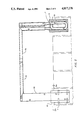
- FIG. 1 is an elevational view, partly in cross-section, of the lead-ins and a pair of coils surrounded by molds for heating and fusing side terminals or posts of a lead-acid storage battery when they are lifted into the molds;
- FIG. 2 is a view partly in cross section taken along line 2--2 of FIG. 1;
- FIG. 2a is a section taken along line 2a--2a of FIG. 2;
- FIG. 3 is a vertical cross-sectional view taken along line 3--3 of FIG. 1;
- FIG. 4 is a partial cross sectional view of FIG. 3 showing only the terminal post and L shaped tombstone before fusion;
- FIG. 5 is a side view of the terminal post and tombstone of FIG. 4 before fusion
- FIG. 6 is a cross sectional view similar to FIG. 4 except showing the terminal post and tombstone after they are fused together;
- FIG. 7 is a side view of FIG. 6 after fusion.
- FIGS. 8, 9 and 10 are front, side and top views of one of the molds.
- numeral 1 denotes a battery case of the lead acid storage type, which case may be of polypropylene or other suitable material.
- Numerals 2 and 3 denoted lead blocks connected, respectively, to lead-in copper buses 4 and 5 of rectangular tubular cross-section for electrically conducting current to coils 6 and 7 of two turns each which coils are connected in series and which are for the purpose of simultaneously fusing the side terminal posts 13 shown in FIGS. 3, 4 and 5.
- a Ferrite block, such as 14, is surrounded by each coil.
- the terminal post 13 and L-shaped tombstone 12 of FIG. 3 are lifted into the structure shown in FIGS. 1-2 and into the corresponding mold 8, as shown in FIG. 3.
- bus 4 leads current through coil 6 having two turns which coil is enclosed in an insulating, glass filled Teflon mold 8 (see FIGS. 8, 9 and 10) for defining the shape of fused material after induction heating by coils 6 and 7 connected in series.
- a Dialecto stud plate 10 of electrical insulating material is fastened by bolts 11 to bus 4 and mold 8.
- the side terminal post 13, extending through battery case 1, has a threaded opening 13 on one side and a projection 13b on the other, which projection extends into a somewhat U-shaped opening 12a of the tombstone 12 of L-shape, as more clearly seen in FIGS. 4 and 5.
- the projection 13b Upon application of induction current through coils 6 and 7 at a frequency of 550 VHZ for about 4.5 seconds, and cooling about 3 seconds, seconds, the projection 13b will fuse and will be integrally connected to the L-shaped tombstone 12 as better shown in FIGS. 6 and 7 to the bottom of which tombstone the battery grid is connected (not shown). Thus both positive and negative side terminals are fused at the same time.
- a speedy way for mass producing fused connections to both side terminals of the battery at the same time is to lift the battery with its tombstone by a fixture (not shown) until obtaining the position shown in FIG. 3 and thereafter applying induction heating current to both induction coils 6 and 7 simultaneously to form two simultaneous fused connections at the two side terminals of the battery similar to that shown in FIGS. 6-7.
Landscapes
- Engineering & Computer Science (AREA)
- Chemical & Material Sciences (AREA)
- Chemical Kinetics & Catalysis (AREA)
- Electrochemistry (AREA)
- General Chemical & Material Sciences (AREA)
- Mechanical Engineering (AREA)
- Manufacturing & Machinery (AREA)
- Connection Of Batteries Or Terminals (AREA)
Abstract
Description
Claims (2)
Priority Applications (1)
| Application Number | Priority Date | Filing Date | Title |
|---|---|---|---|
| US07/224,989 US4817278A (en) | 1988-07-25 | 1988-07-25 | Side terminal connection by fusing |
Applications Claiming Priority (1)
| Application Number | Priority Date | Filing Date | Title |
|---|---|---|---|
| US07/224,989 US4817278A (en) | 1988-07-25 | 1988-07-25 | Side terminal connection by fusing |
Publications (1)
| Publication Number | Publication Date |
|---|---|
| US4817278A true US4817278A (en) | 1989-04-04 |
Family
ID=22843082
Family Applications (1)
| Application Number | Title | Priority Date | Filing Date |
|---|---|---|---|
| US07/224,989 Expired - Fee Related US4817278A (en) | 1988-07-25 | 1988-07-25 | Side terminal connection by fusing |
Country Status (1)
| Country | Link |
|---|---|
| US (1) | US4817278A (en) |
Cited By (2)
| Publication number | Priority date | Publication date | Assignee | Title |
|---|---|---|---|---|
| USD331411S (en) | 1990-03-01 | 1992-12-01 | Agape Plastics, Inc. | Engine compartment terminal box |
| US20090126230A1 (en) * | 2004-06-04 | 2009-05-21 | Nike, Inc. | Article Of Footwear With Outsole Web and Midsole Protrusions |
Citations (4)
| Publication number | Priority date | Publication date | Assignee | Title |
|---|---|---|---|---|
| US4150202A (en) * | 1977-02-02 | 1979-04-17 | Tiegel Manufacturing Company | Method for making a side terminal weld and product produced by that method |
| US4446214A (en) * | 1979-02-26 | 1984-05-01 | The Richardson Company | Method for forming a metal casting extending through a preformed structure and articles produced thereby |
| US4573260A (en) * | 1985-06-28 | 1986-03-04 | The Taylor-Winfield Corporation | Induction heated intercell fusion for lead/acid storage battery |
| US4642442A (en) * | 1985-10-17 | 1987-02-10 | The Taylor-Winfield Corporation | Battery intercell connection by induction heating |
-
1988
- 1988-07-25 US US07/224,989 patent/US4817278A/en not_active Expired - Fee Related
Patent Citations (4)
| Publication number | Priority date | Publication date | Assignee | Title |
|---|---|---|---|---|
| US4150202A (en) * | 1977-02-02 | 1979-04-17 | Tiegel Manufacturing Company | Method for making a side terminal weld and product produced by that method |
| US4446214A (en) * | 1979-02-26 | 1984-05-01 | The Richardson Company | Method for forming a metal casting extending through a preformed structure and articles produced thereby |
| US4573260A (en) * | 1985-06-28 | 1986-03-04 | The Taylor-Winfield Corporation | Induction heated intercell fusion for lead/acid storage battery |
| US4642442A (en) * | 1985-10-17 | 1987-02-10 | The Taylor-Winfield Corporation | Battery intercell connection by induction heating |
Cited By (6)
| Publication number | Priority date | Publication date | Assignee | Title |
|---|---|---|---|---|
| USD331411S (en) | 1990-03-01 | 1992-12-01 | Agape Plastics, Inc. | Engine compartment terminal box |
| US20090126230A1 (en) * | 2004-06-04 | 2009-05-21 | Nike, Inc. | Article Of Footwear With Outsole Web and Midsole Protrusions |
| US8474155B2 (en) | 2004-06-04 | 2013-07-02 | Nike, Inc. | Article of footwear with outsole web and midsole protrusions |
| US8919016B2 (en) | 2004-06-04 | 2014-12-30 | Nike, Inc. | Article of footwear with outsole web and midsole protrusions |
| US9883715B2 (en) | 2004-06-04 | 2018-02-06 | Nike, Inc. | Article of footwear with outsole web and midsole protrusions |
| US10905195B2 (en) | 2004-06-04 | 2021-02-02 | Nike, Inc. | Article of footwear with outsole web and midsole protrusions |
Similar Documents
| Publication | Publication Date | Title |
|---|---|---|
| KR950004628B1 (en) | Cathode for Lead Storage Battery | |
| CN105914408B (en) | A kind of lead-acid accumulator and electric vehicle | |
| US4854894A (en) | Intermediate component for an electrical connector and method of manufacture | |
| US2033643A (en) | Method of making electric sockets | |
| US5659946A (en) | Method of manufacturing a multicell battery | |
| US4171564A (en) | Method of manufacturing electric batteries with heat embedded intercell connectors | |
| ITFI950049A1 (en) | METHOD AND DEVICE FOR THE MAGNETIC DEFORMATION OF METAL BODIES | |
| US4817278A (en) | Side terminal connection by fusing | |
| US4642442A (en) | Battery intercell connection by induction heating | |
| US4078122A (en) | Battery terminal construction | |
| US4395375A (en) | Method of electrically testing molded cord-sets during the molding operation | |
| CN209929212U (en) | Insulating pole | |
| US1993410A (en) | Electric heater and method of making the same | |
| US2385386A (en) | Method of making resistors | |
| US2337937A (en) | Electric fuse | |
| EP1139463A2 (en) | Method and apparatus for manufacturing battery module and unit battery cell for use in battery module | |
| CN210442465U (en) | Core withstand voltage test equipment after coiling | |
| US3947955A (en) | Method of making an inductive stabilizing ballast for a gas and/or vapour discharge lamp | |
| CN220822161U (en) | Type-C connector with identification resistor | |
| US3654696A (en) | Method for manufacturing electric fuses | |
| US4573260A (en) | Induction heated intercell fusion for lead/acid storage battery | |
| US4691266A (en) | Electric doublelayer capacitor | |
| KR101897155B1 (en) | Lead Insertion Into Center Core Type Capacitor | |
| JPH05506121A (en) | Electromagnetic relay and its manufacturing method | |
| CN211670091U (en) | Easily-formed manufacturing structure of surface-mounted inductor |
Legal Events
| Date | Code | Title | Description |
|---|---|---|---|
| AS | Assignment |
Owner name: TAYLOR-WINFIELD CORPORATION THE, 1052 MAHONING AVE Free format text: ASSIGNMENT OF ASSIGNORS INTEREST.;ASSIGNOR:MULLANE, WILLIAM E.;REEL/FRAME:004966/0422 Effective date: 19880715 Owner name: TAYLOR-WINFIELD CORPORATION, THE, OHIO Free format text: ASSIGNMENT OF ASSIGNORS INTEREST;ASSIGNOR:MULLANE, WILLIAM E.;REEL/FRAME:004966/0422 Effective date: 19880715 |
|
| FPAY | Fee payment |
Year of fee payment: 4 |
|
| REMI | Maintenance fee reminder mailed | ||
| LAPS | Lapse for failure to pay maintenance fees | ||
| FP | Lapsed due to failure to pay maintenance fee |
Effective date: 19970409 |
|
| STCH | Information on status: patent discontinuation |
Free format text: PATENT EXPIRED DUE TO NONPAYMENT OF MAINTENANCE FEES UNDER 37 CFR 1.362 |